Week 11 - Final project
AIM:
To design a Door Panel of an Automotive
- To create an assembly and organize different surfaces of the given class A surface into different parts of the door trim panel. To create a tooling axis and perform a draft analysis on the class A surface of each part.
To create class B, class C surface, and close surface for each part.
- To perform draft analysis on the close body of each part.
- To create engineering features (Heat stakes, Locators, Dog House) to join the parts of the door trim panel together.
- To assemble push pins to the door panel.
INTRODUCTION:
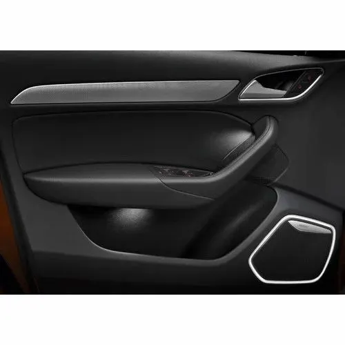
A door panel, also known as a door card, is an insert that covers the interior components of a vehicle's door. Modern cars often have door cards that are constructed of plastic and incorporate other decorative elements, with injetion molding being the most common method. Other features that add to the vehicle's aesthetic, functionality, and ergonomics are usually included in the door panel. Armrests, s witches, or other controls for the windows and locking mechanism, convenience lights, speakers, storage compartments, and other features are examples of this.
Material Used For Production Of Door Panel:
The Interior Part Of The Door Assembly Generally Manufactured By
- Polypropylene (Pyp)
- Acrylonitrile Butadiene Styrene (Abs)
- Polyvinyl Chloride (Pvc)
- Polyphenylene Ether (Ppe)
Major Components Of Door Trim:
These Are The Components Which We Work On This Project-
- Lower Substrate
- Door Armrest
- Bottle Holder
- Map Pockets
Task To Perform On This Project:
- Creation Of Tooling Axis
- Creation Of Class A, B, And C Surface
- Creation Of Closed Surface Of All The Components
- Creation Of B Side Features
- To Perform Draft Analysis
Lets create each part step by step.
LOWER SUBSTATES:
Creating the Tooling Axis
It Is The Direction In Which The Core And Cavity Move. We Will Required Multiple Tooling Axis For Each Component . We Will Also Work On The Side Core Axis.
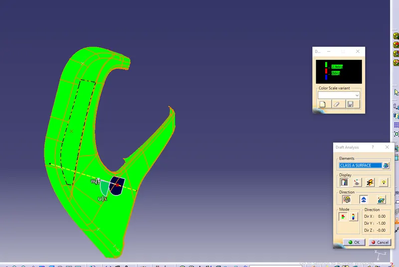
We Will Create A Tooling Axis For The All The Components.For Clearing The Toolinng Axis For Door Arm Resr We Hav To Use The Compass And Lock The Oreatnaton Where The Tooling Axis Show The All Green In The Draft Analysis Under The 3 Degree Angle. As For The Lower Substrate And Map Pocket, We Will Directly Go Fot The Natural Tooling Axis Y-Direction.
CLASS B SURFACE
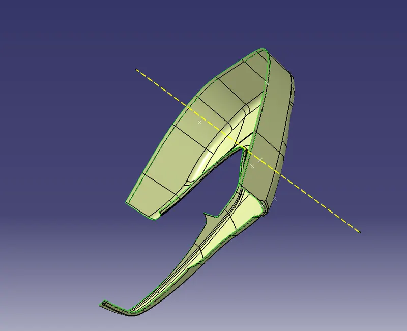
Class B Is Generally At The Backside Of The Class A Surface And It Is The Offset Part Of The Class A Surface and extrpolated edges of the B surface for use to trim with C surface.
CLASS C SURFACE
Create boundary from the A surface of Lower substates.
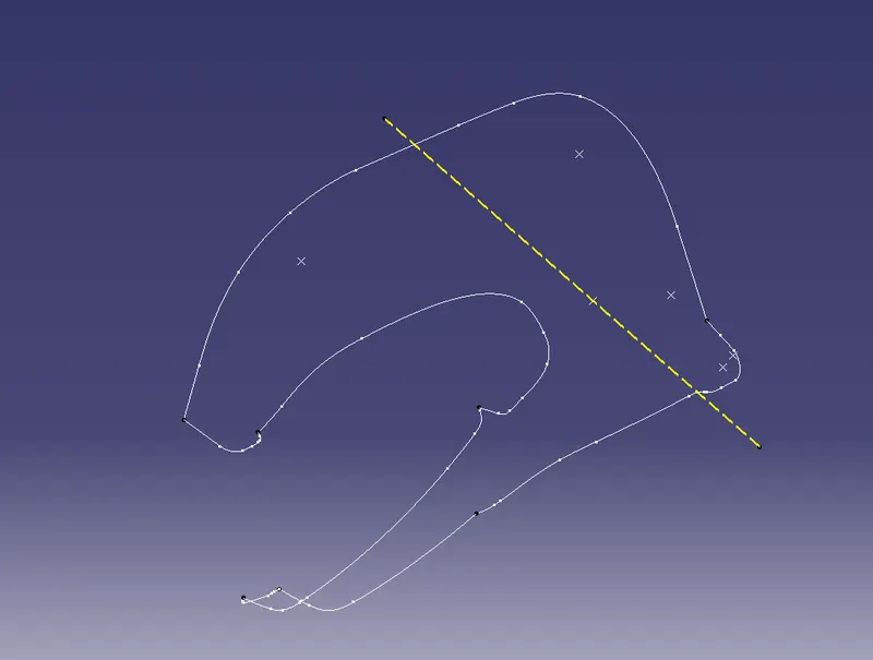
Create sweep from the created boundary of A Surface in angle of 3 degree ad 90 degree which based of the surfaces.
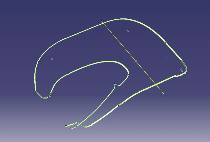
Incase, some curf surface formed in the sweep so we have to resolve those surfaces by using remove the curfs abd create multi sections in removed portions.
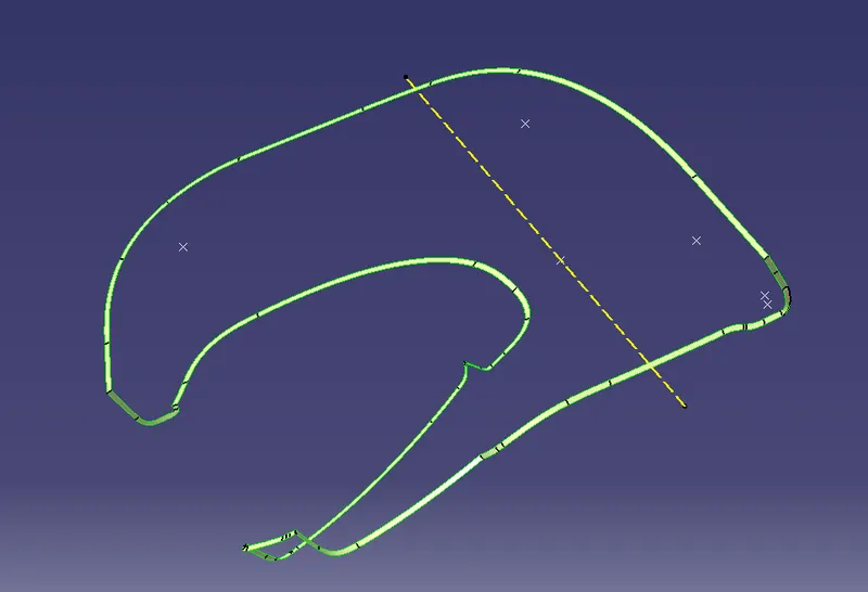
After creation of C surfaces trime with A surface.
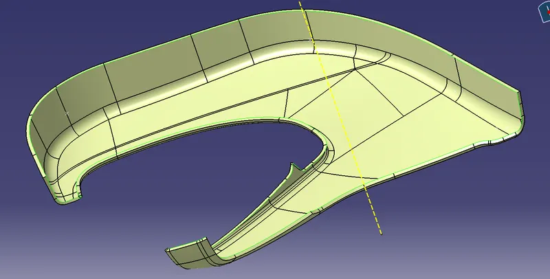
Finally in the lower substates, trim A and C surfaces with extrapolated B surface.
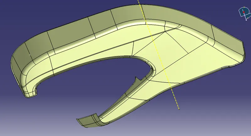
MAP POCKET
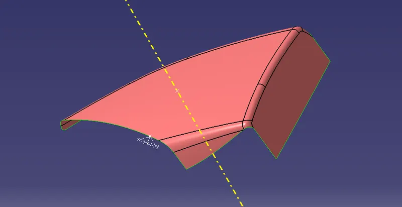
Given Class A surface
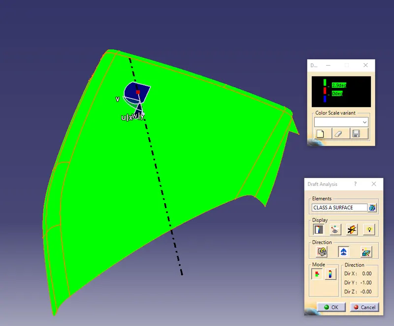
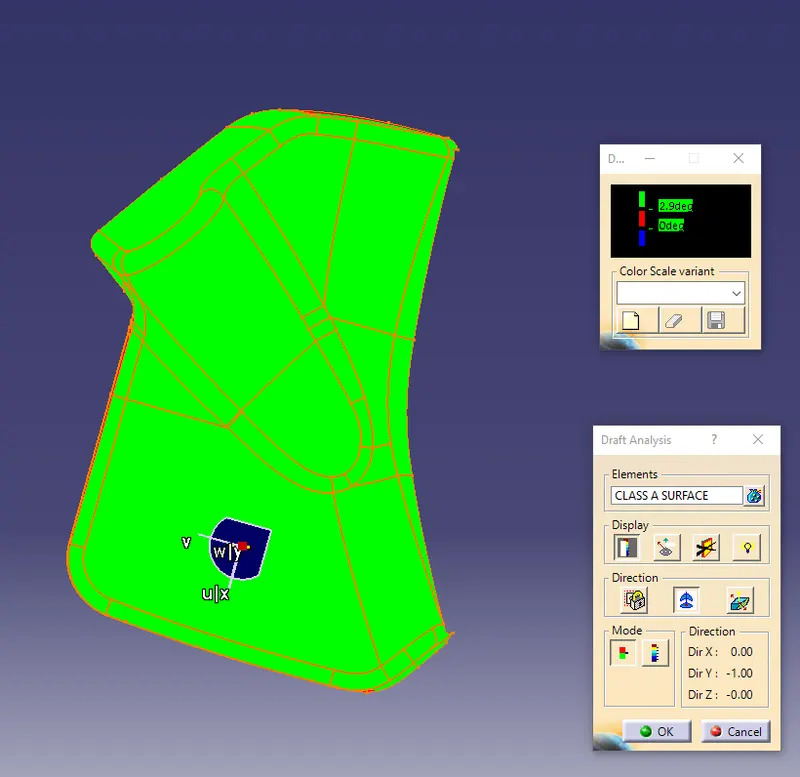
Draft Analysis for Given A surface Map pocket.
CLASS B SURFACE
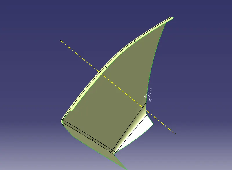
Similarly Offset 2.5mm from the A surface to create B surface
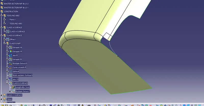
In the B surface, some patches are formed and have to solve the patches like below in the pictures.
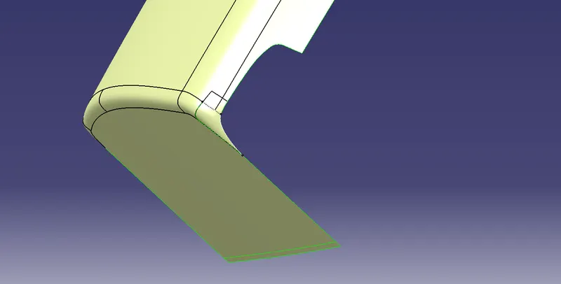
Extrapolated the edge of B surface upto particular dimesions.
CLASS C SURFACE
Similarly, take boundary form the edge of the A surface between sharp edges.
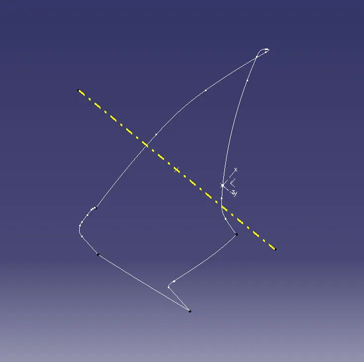
Create sweep from the taken boundary in 90 degree and 3 degree depends on the edges.
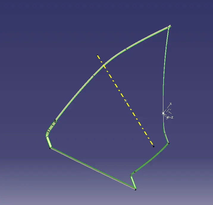
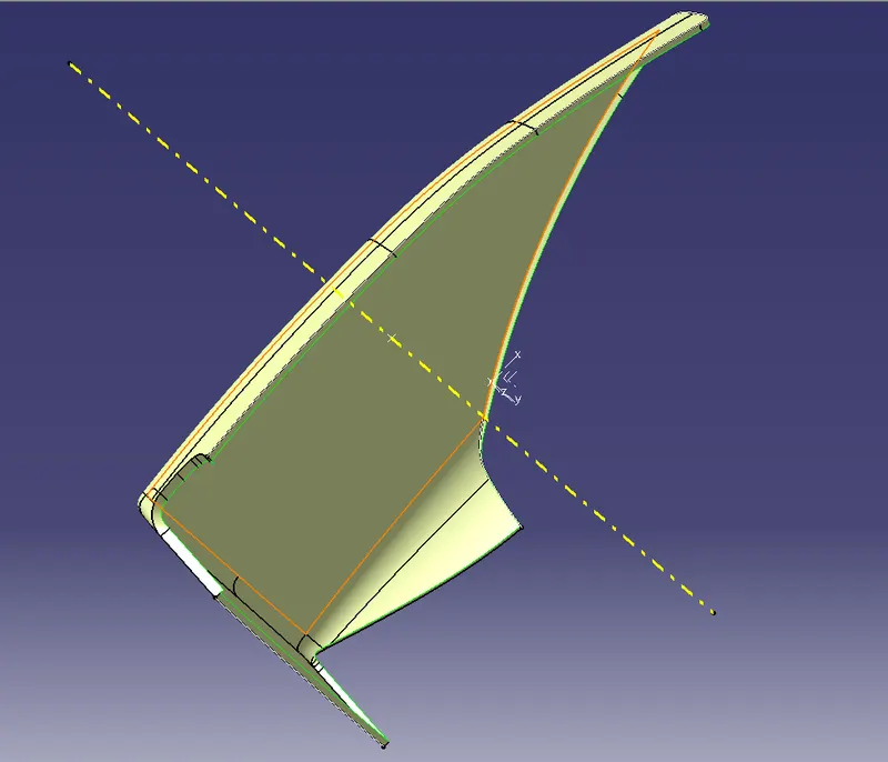
JOIN A and C SURAFCE:
Trimmed the A Surface and C Surface.
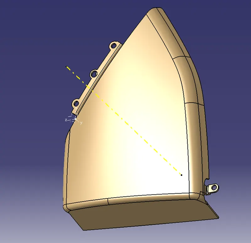
BOTTLE HOLDER
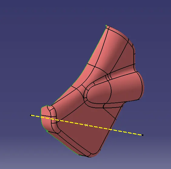
The given A surface of Bottle Holder.
Draft analysis
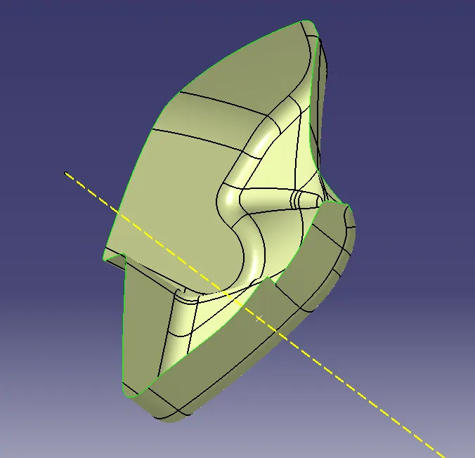
CLASS B SURFACE
Offset the A Surface 2.5mm to create B Surface, if any patches are form have solve the discontinuties.
CLASS C SURFACE
As it is in the previous component, have to create boundary from the A surface.
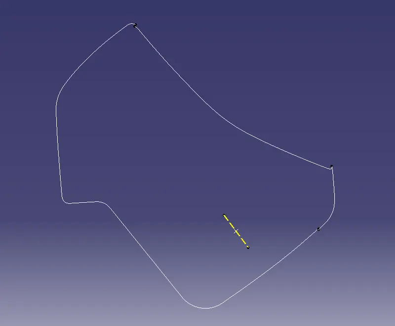
Create sweep from the boundary with respect to surface in same angles.
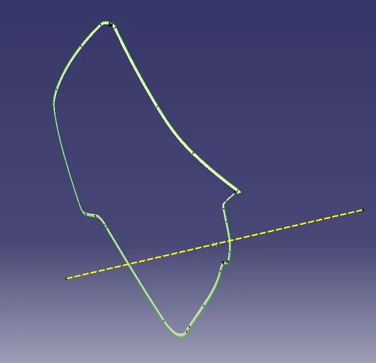
Trimmed the C surface with given A surface
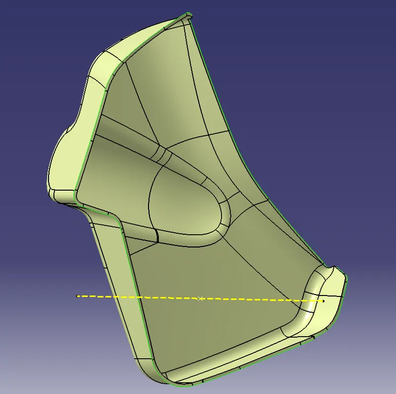
Final in the bottle holder, trim the B surface with trimmed A and C surface.
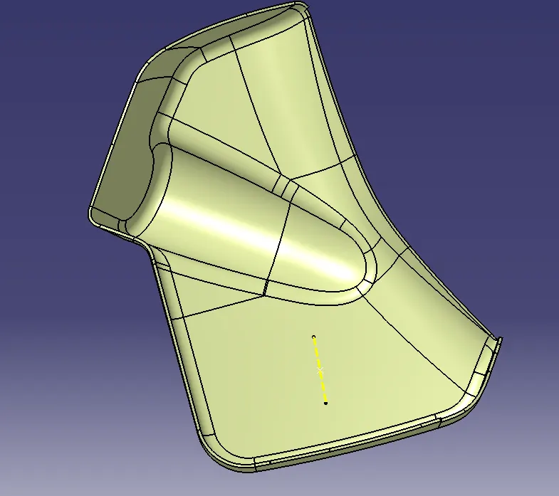
DOOR ARM REST
Given A surface of Door arm rest component and creation Tooling axis and Slider axis with repspect to tppoint and direction.
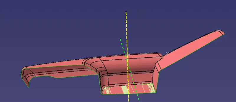
DRAFT ANALYSIS:
Analysing Draft analysis for Door arm rest in order to tooling axis and slider axis.
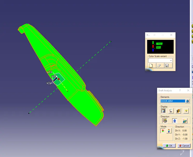
CLASS B SURFACE:
Offset the A surface to create B surface
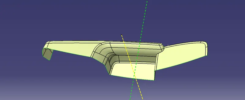
In the offsetted B surface, have to improve the patches which using multisection tool and spli with two edges and join with B surfaces.
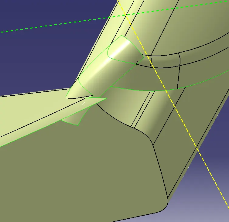
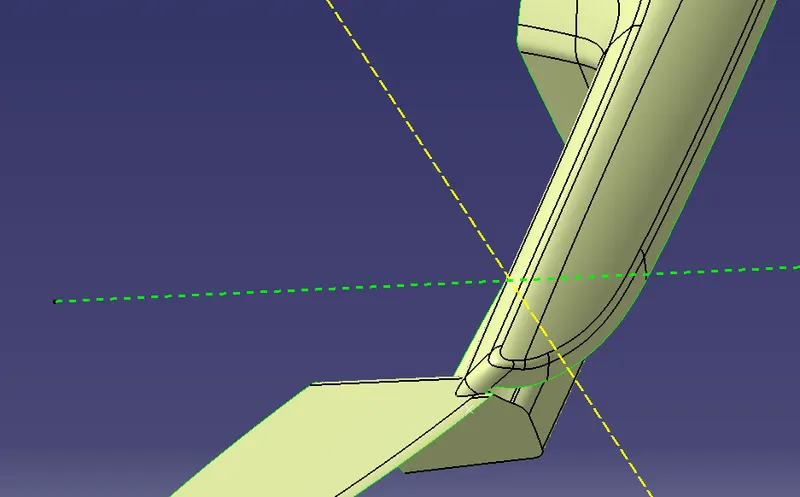
After the solve the B surface of Door arm rest and extrpolate all the edges with particular dimension.
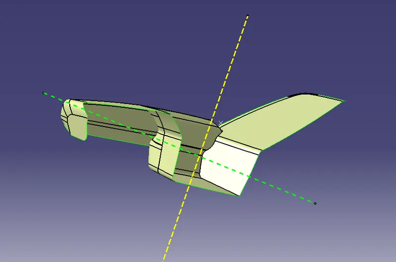
CLASS C SURFACE:
Take boundary from the A surface as possible edges without more curvature surfaces.
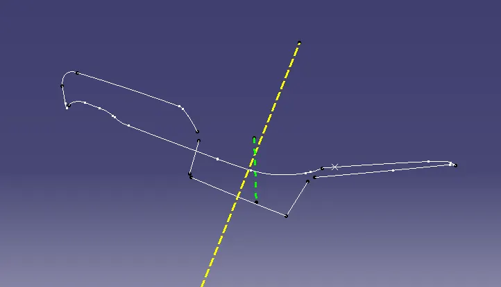
Sweep the boundary with respect to A surface and remaining portion have to create multi section in the curvature with help of spline in tangency.
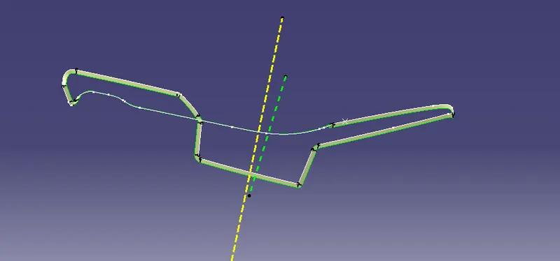
Trim A surface and C surface
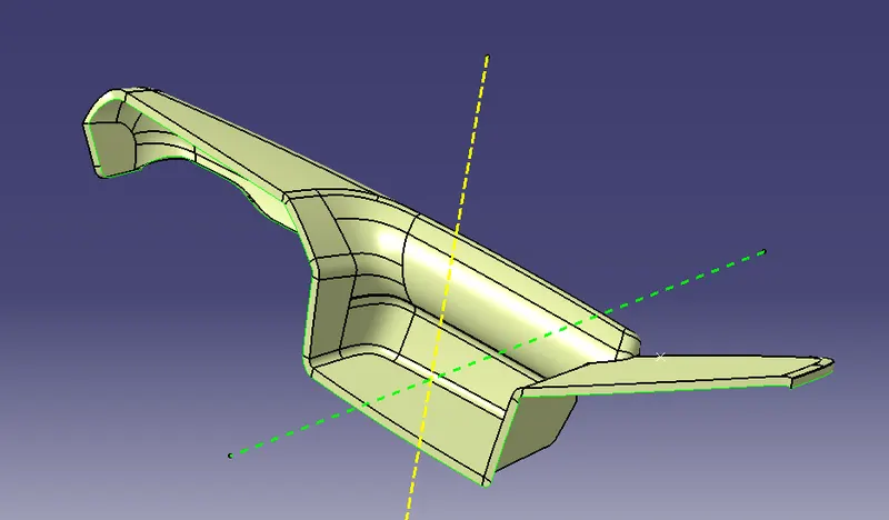
Final in the Door arm rest , trim B surface with trimmed A and C surface to form a closed part.
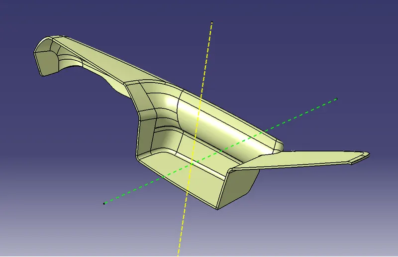
Change the closed surface to solid component by uiosng close surface tool in the part workbench.
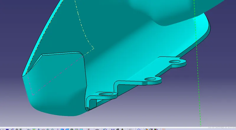
CREATION OF FLANGE:
Flange is
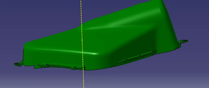
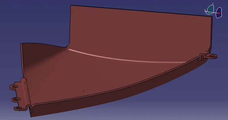
With reference of given master section have to create flanges in the Door arm rest and Map pocket
HEATSTAKES
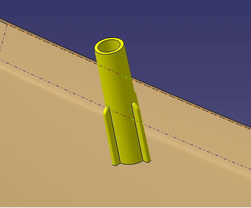
Heat staking is a pulsed – heat process to join two or more parts out of which one at least is made of plastic . The plastic is to deform the plastic material using the heat and foam at a set process time. The bond is made by partially de forming the plastic part in order to fix the other. Heat stakes makes it easily to bond metal to plastic is commonly used in high volume and low cost application such as Automotive, IT and consumer appliances. Here we shoulf give ribs for the heatstakes for increase strenght of the heastakes.
LOCATORS
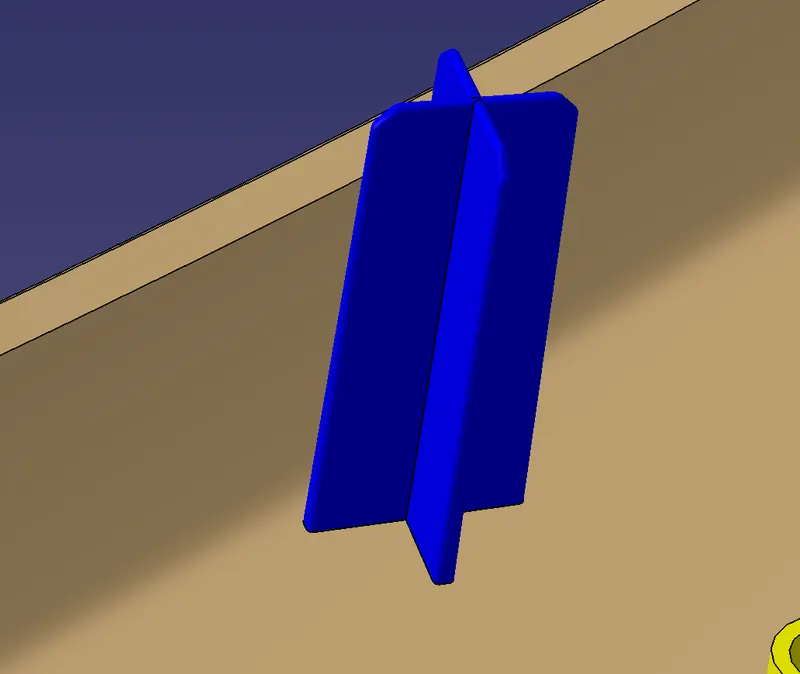
4 WAY LOCATORS:
- To create 4 Way locators, the ribs should be created intersecting with each other.
- Open the Sketcher Workbench and Draw 2 lines intersecting each other and constraint it.
- Exit the Sketcher Workbench and Pad the Sketch with a thickness of 1.2 mm.
- Now, provide a draft of 0.5 degrees to the faces. Here the pulling direction is the tooling axis and the neutral face is the top face.
- Provide the chamfer of 3*45 to the edges of the locators.
- For the 2-way locators, only a single line needs to created and the rest procedure is the same as 4-way locators.
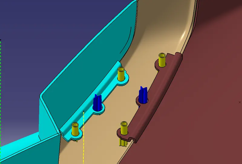
we created the heatstakes in which required positon by using principle of degree of freedom along with flanges in the door trim assembly.
DOG HOUSE
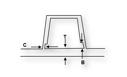
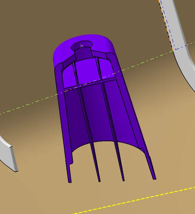
Dog house is an engineering feature used in plastic trim design. Dog houses are used as supporting feature. Sometimes other engineering features like snaps; locators etc. are mounded on them to increase their strength. Dog houses are subjected to draft analysis to prevent breakage of the component during ejection from mould cavity. Dog house and other engineering components are built on B-surface
Design Rules.
-
Doghouse wall thickness at the intersection of the part wall ( C ) should be 40% or less than the main wall stock ( T ).
-
Height of ( B ) should be between 3.0 – 6.0 mm
RIBS
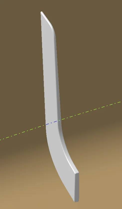
These Are The Components Which Provide Strength And Stiffness Without Using Overall Thickness. They Are The Feature In Plastic Injection Molded Parts.
Design rules fo ribs
lets consider Nominal Wall thickness is T
Thickness of rib - 0.3T to 0.7T
Height of the rib - less than 5T
Space between two ribs - more thant 4T
Fillet radius of rib- T/8 or 0.25mm max
Draft angle of rib - 0.5 degree
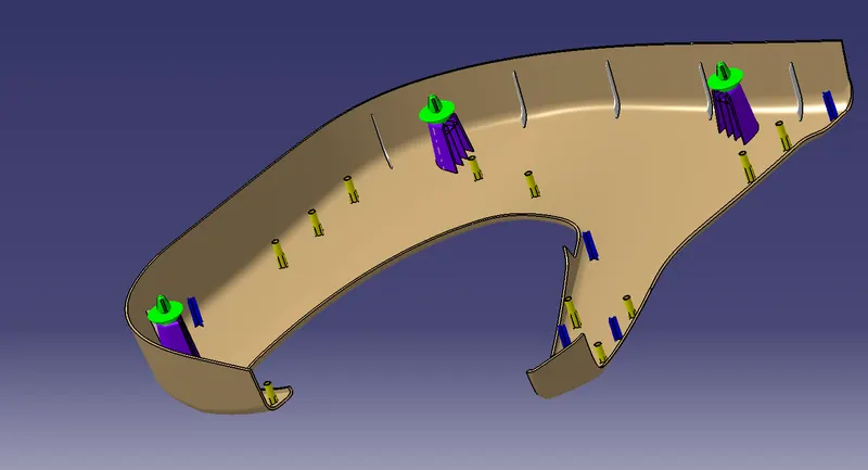
FINAL LOWER SUBSTATES WITH ENGINEERING FEATURES:
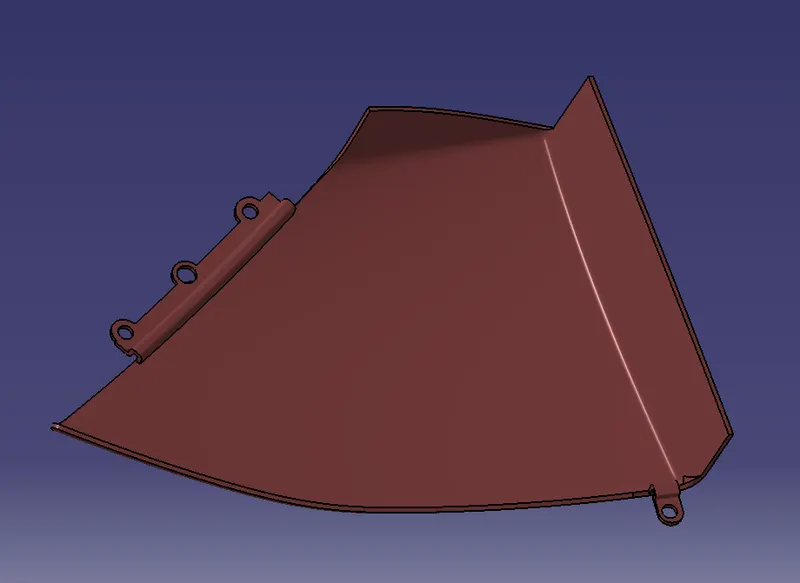
FINAL MAP POCKET:
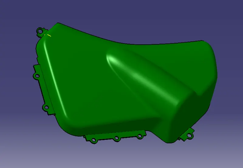
FINAL BOTTLE HOLDER:
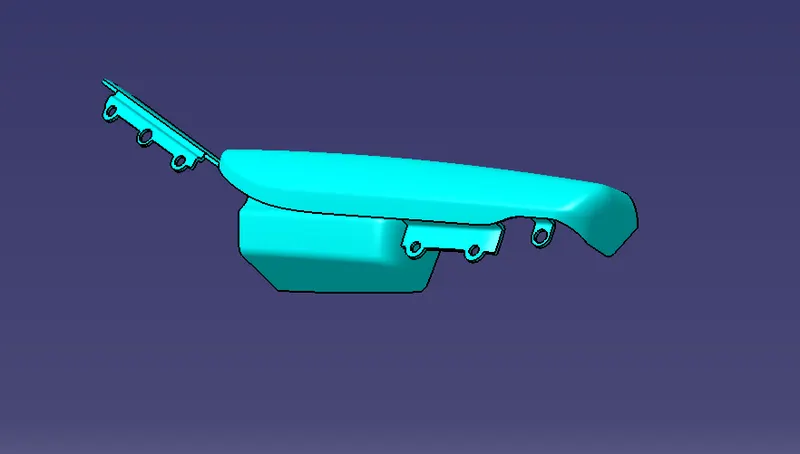
FINAL DOOR ARM REST:
DOOR TRIM ASSEMBLY
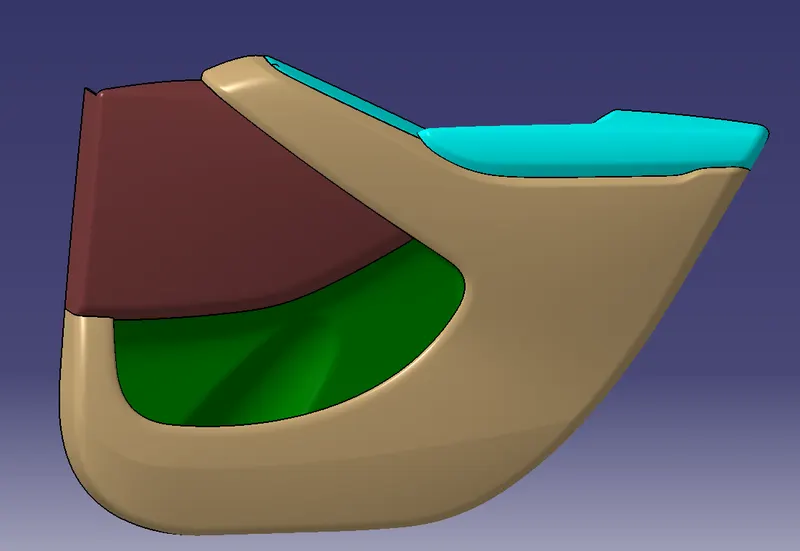
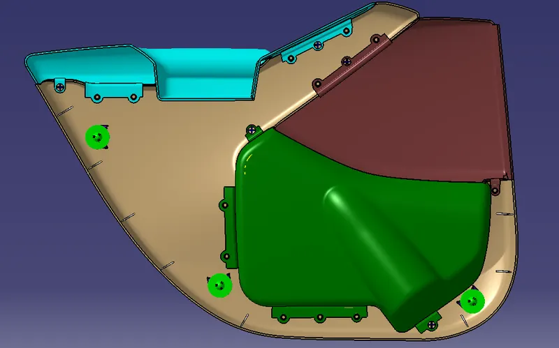
ISOMETRIC VIEW OF DOOR TRIM COMPONENT.
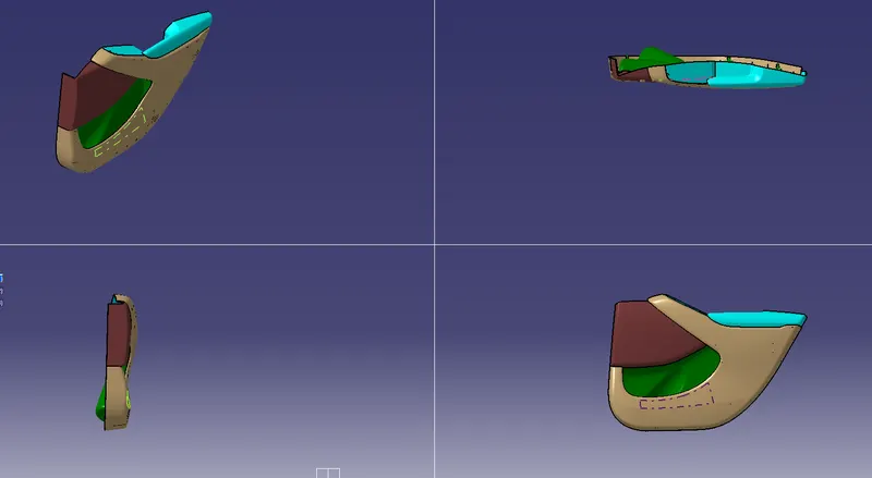
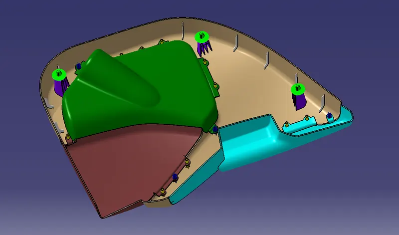
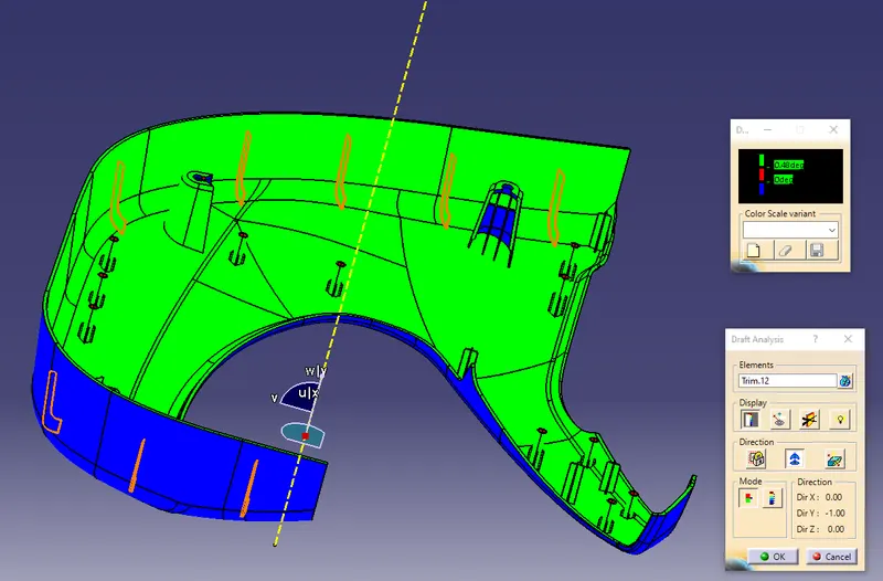
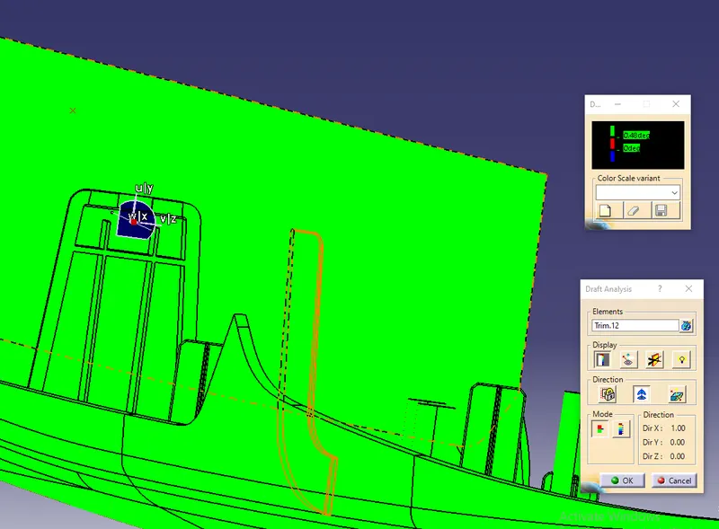
DRAFT ANALYSIS FOR TO ALL COMPONENT WITH ENGINEERING FEATURES.
First we have to set the compass on the main tooling axis to get the direction of core and part moves along as shown below.
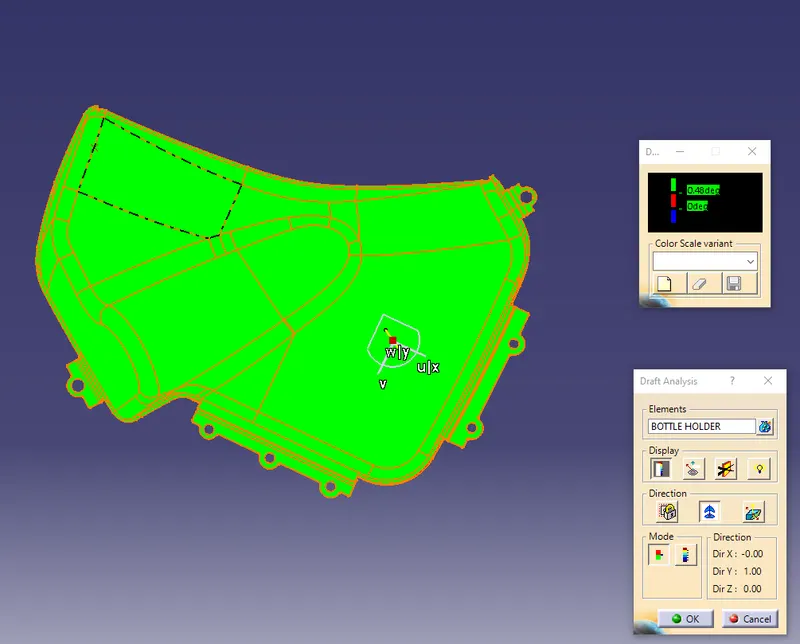
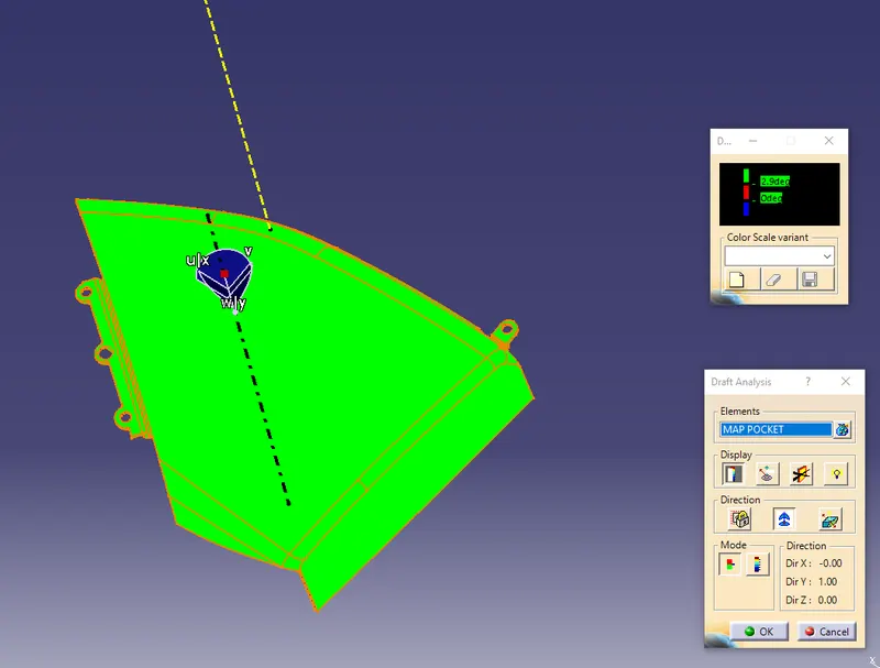
Here the draft angle is given as 3 degree. Hence we achieved green colour on top surface. Hence it accepts the draft angle for the surface, so we build good quality component.
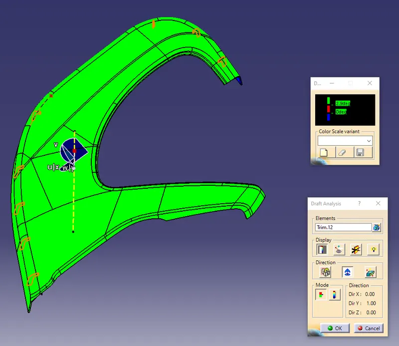
Now we check colour variant scale to ensure the maximum and minimum area draft angle is achieved by displaying by green, red and blue colour respectively. If the surface appears red in colour while analysing it is not accepted.
We can check the angle of draft given to surface by using draft tool analysis just point the over the surface where we have check angle of given draft to the component as shown below.
Lower substates
Bottle Holder
Map Pocket
Door Arm
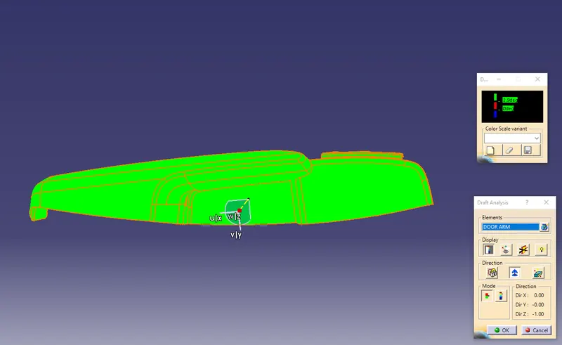
A sliding axis for the Arm rest component has been done separately by using sliding tooling axis as shown below.
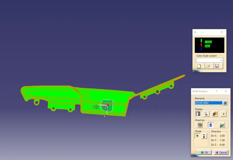
For Attachment Features the draft angle is applied for 0.5 deg and its analyzed using the sliding tooling axis as shown below.
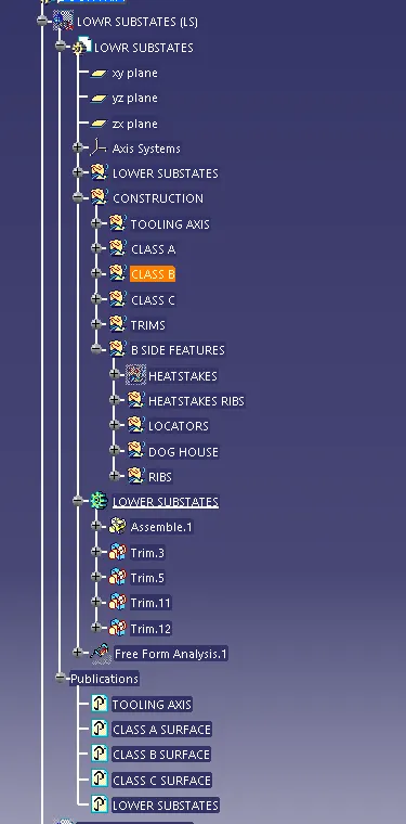
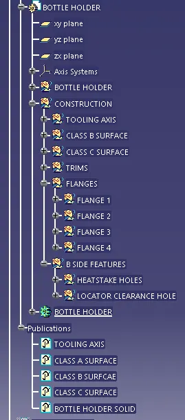
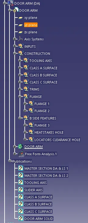
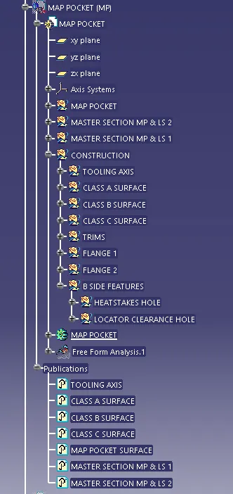
TREE STRUCTURES:
CONCLUSION
Creation of the car interior door trim is designed using the given class A surface as the input and Class B and C surface created with the help of Class A surface. By using the given master section attachment features I.e. Heat stakes, Flanges, Dog House and Push Clips are created using the design rules. The draft analysis has been performed to analysis the draft of the component to manufacture easily applying draft to the surface by 3 degree and 0.5 degree to the attachment features. With all data and report we can conclude that draft analysis is very important to design any plastic component to mold the plastic easily. The analysis will verify that all surfaces are favorable for being pulled from a cavity. It may also highlight or given insight to defect areas.