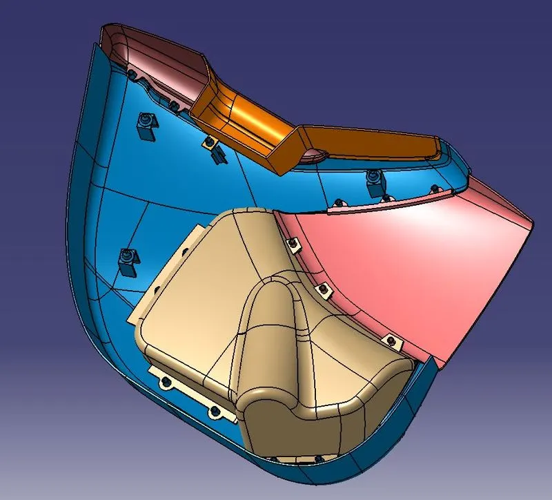
Door Panel
Aim:
The development of door panels with Class A,B and C surfaces and run with Draft Analysis.
Theory:
Door panels serve as an interface between the car and the inner workings of the door, and between vehicle occupants and the door. It is one of the most important components in the interior of a car. It contains a lot of electrical components like speakers, window slider, and door lock systems etc. The door panel evolves from a two-part system of latch and simple winding system to the more sophisticated enclosure.
Ribs:
Ribs provide a mean to economical stiffness and strength in moulded parts without increasing overall wall thickness. They also facilitate
- Locating and arresting components of an assembly.
- Providing alignment in mating parts.
- Acting as stops or guides for mechanisms.
Dog house:Dog house is an engineering feature used in plastic trim design. Dog houses are used as supporting features. Dog houses are subjected to draft analysis to prevent breakage of the component during ejection from mould cavity. Dog house and other engineering components are built on B-surface.
Dog house wall thickness should be 40% or less than main wall thickness.
Locators:
Locators are used to locks the component when it is fitted.
Purpose:
To convert the surfaces into solids we need to create Class B & C surfaces which are used for thickness. Class B surface determines the lower surface and Class C surface joins the Class A & B surfaces.
Procedure:
Inspecting & Segregating the Class A surface:
The given model has class A surface along with some master sections for features.
- Inspect the model using Boundary option and notice it if any discontinuity for the surface.
- Segregate the components as they already displayed with different colours.
- Rename the segregated components and arrange it in order.
Tooling Axis:
- Create a line normal to the surface and perform Draft Analysis.
- Make sure the line clears the Draft Analysis.
- Thicken the lines and rename it according to the component.
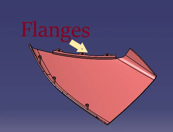
Flanges:
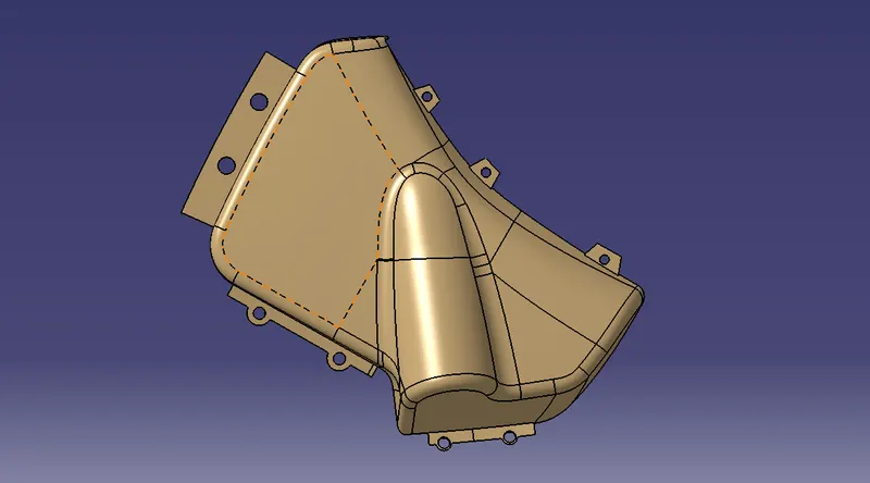
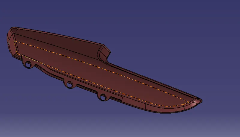
- For connection of different solids, flanges are created on the Class A surface.
- Map Pocket and Arm Rest need to be connected with the lower substrate.
- Extrapolate the Class A surface.
- Create a sketch and trim it.
- Offset the trimmed surface with thickness value and make it as a closed surface.
Class B surface:
- Measure the thickness of the model and offset to the measured value.
- If any errors occurred, then extract the surrounding surfaces/lines/edges.
- Create a new surface with extracted surfaces.
Class C surfaces:
- Extract the edges of Class A surfaces.
- Sweep the edges with tooling direction of draft angle 3degrees along Class B surface.
- If any errors occurred at curved surfaces use the Multi Section Surface or Blend option.
Joining the Surfaces:
- Join the Class A and Class C surfaces.
- Trim the joined surfaces with Class B surface.
- Errors need to be corrected while performing trimming operations.
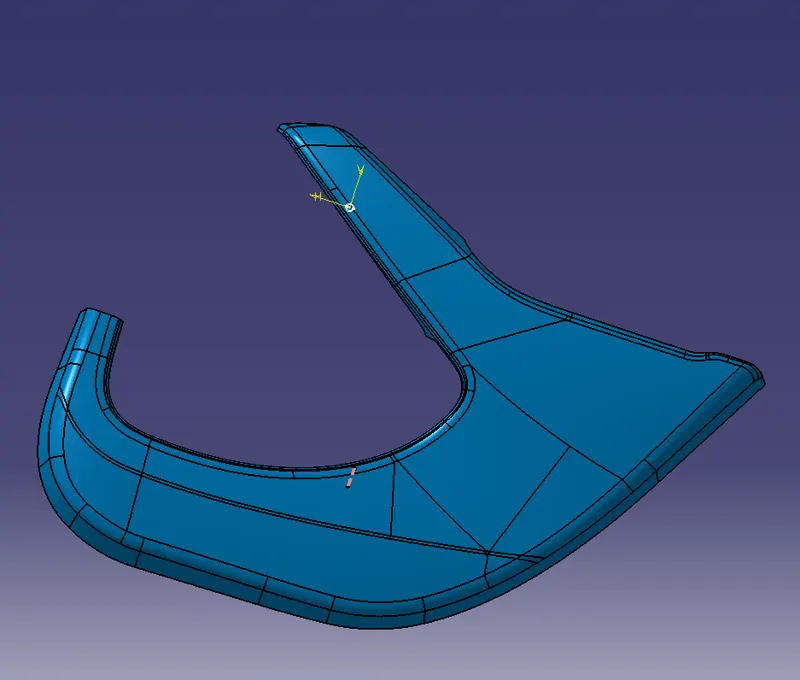
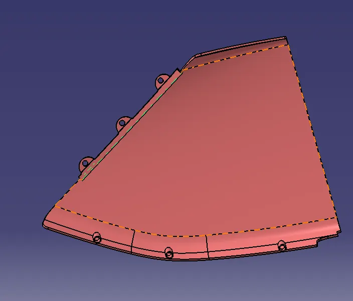
Arm Rest:
Arm rest needs two tooling axes as there is bin like structure, so they are segregate into two parts
- Upper Arm Rest
- Lower Arm Rest
Upper Arm Rest:
- Class A surface is checked and draft analysis is done to obtain the tooling axis.
- Sweep the Class A surface along X axis and create a new sketch on the surface.
- Spilt the new sketch with the surface and the Join the newly surface with Class A surface.
- Offset the Class A surface of 2.5mm thickness value, rename it as Class B surface.
- Reconstruction should be done if any errors occur while offsetting the surface.
- To construct the Class C surface, extract the edges of Class A surface.
- Sweep the edges with the draft angle of 3degrees along the tooling axis direction.
- Use Multi Section Surface or Blend for the curved surfaces for class C surfaces.
- Use the Boundary option, if there are any non continuous surfaces.
- Go to Part workbench, use the Closed Surface option to convert it in solid.
- Perform the Draft Analysis and check the model.
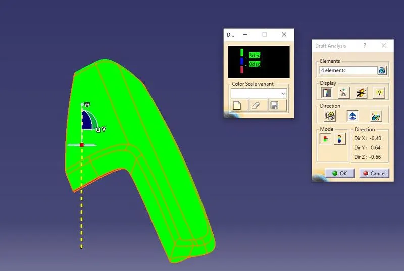
Lower Arm Rest:
- Inspect the Class A surface using the Boundary option.
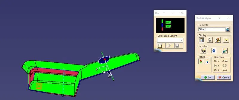
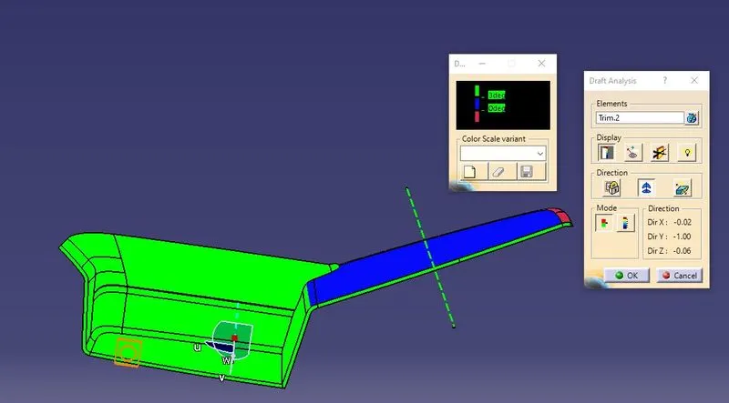
- Perform the Draft Analysis and lock the compass in which direction the model is satisfied.
- Create a line in locked compass direction and rename it as the tooling axis.
- Repeat the same steps for bin structure of lower arm rest.
- Offset the Class A surface to 2.5mm distance and rename it as Class B surface.
- Repeat the steps as used in upper arm rest.
- Perform the Draft Analysis twice, and check the solid model created.
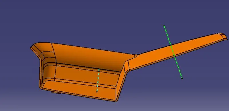
Features:
Ribs:
- Create a new ribs sketch.
- Go to the part workbench and perform a pad with thickness of 1mm.
- Boolean Operations is done to attach the features to the main body.
Dog house:
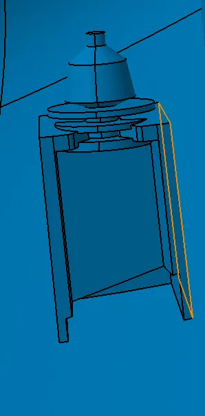
- The dog house is used to mount the pushpins and gives strength to the body.
- Draw a 3 sided rectangle in a new sketch.
- Extrude the surfaces and offset with 2.5mm.
- Extend the surface towards the offset surface.
- Trim the extra surface and convert it into a closed body.
- To get a closed body go to part workbench and used Closedsurface option.
- Offset the Class B surface and trim the offset surface with solid created previously.
- Draft all the surfaces with 3deg angle.
- Translate the doghouse to different locations.
- Using Boolean Operations, attach the dog house to the main body.
Heat steaks:
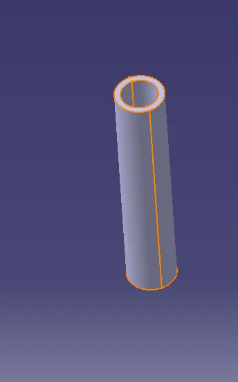
- To constraints the degrees of freedom, heat steaks are used.
- Create a circle of diameter 8mm in a sketch.
- Extrude the surface and use the thicken option (2mm) in the Part workbench.
- Use Copy and Translate options to create a new heat steak in a new location.
- Perform Union Trim to attach heat steaks to different parts of the model.
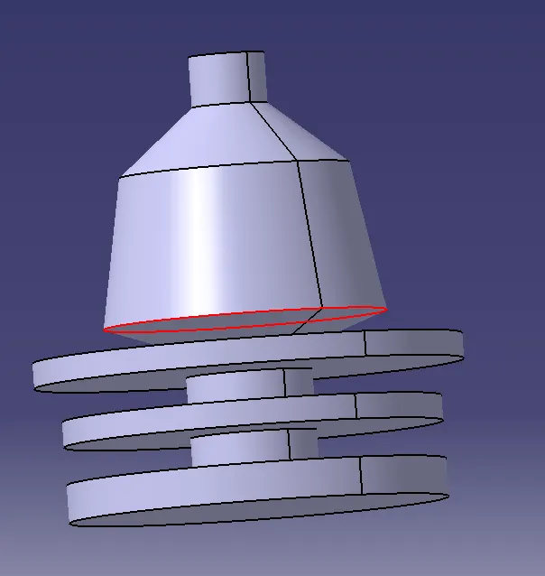
Pushpin:
- Push Pins are attached to doghouse which locks the components and fit in it.
- Create a new sketch in part workbench, draw a pushpin sketch with a free hand option.
- Exit the sketch and perform Shaft by selecting the sketch and the axis.
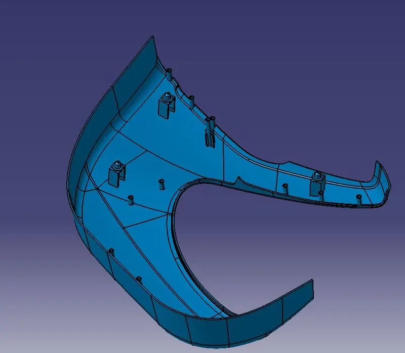
Lower Substrate with features
Draft Analysis:
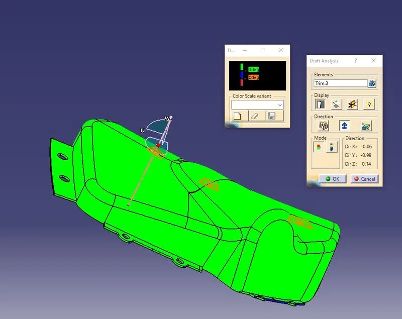
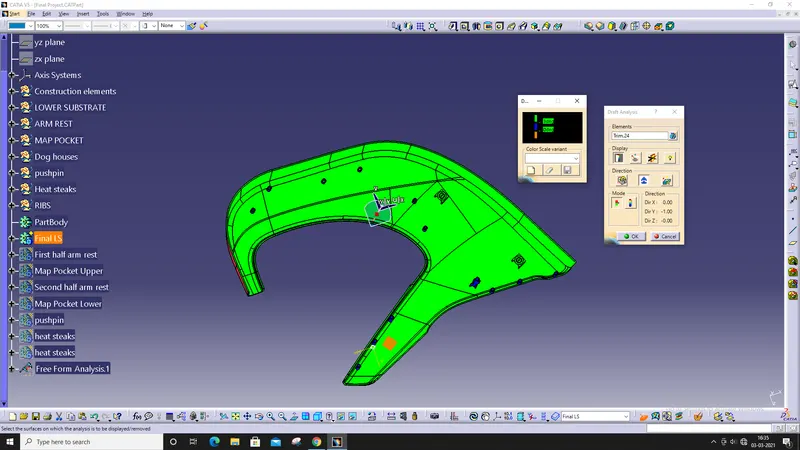
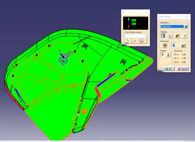
Result:
The solid model is created for the given Class A surfaces, and performed the Draft Analysis for all the components.