Week 11 - Final project
Aim: Create a door panel with the given input's Class A surface, master sections with reference of OEM's and tier1 companies using CATIA V5.
Objectives:
- Create a thickened part for the given Class A surface.
- Create a mounting features for the Door panel.
- Do the draft analysis for the Class A surface as well as the mountings with reference to tooling axis.
Inputs:
- Class A surface
- Mastersections
- Push pins
Introduction: Door panels serve as an interface between the interior of the car and the inner workings of the door, and between vehicle occupants and the door. Door panels, also known as door cards, are the inserts of a vehicle that are used to cover the internal components of the door. These are made of acrylonitrile-butadiene-styrene (ABS), ABS/polycarbonate alloys, polycarbonates, polypropylene, modified polyphenylene ether (PPE) and SMA (styrene-maleic anhydride) resins.
Class A surface: Class A surfaces can be defined as any surface, that has styling intent, that is either seen, touched, or both. A common method of working is to start with a prototype model and produce smooth mathematical Class A surfaces to describe the product's outer body. From this, the production of tools and inspection of finished parts can be carried out. Class A surfacing complements the prototype modelling stage by reducing time and increasing control over design iterations.
Draft analysis: Draft analysis is the technique which is used to check the catpart whether it is designed on the basis of the draft condition. We are providing a direction in which components should eject in order to get an easy removal of components from the tool. In other words, it also lets us know whether the model is having a draft angle and how much is the draft angle from the tool direction. The major consideration of Draft Analysis is whether sufficient Draft Angle is provided on the component. Components while designing should be provided with a considerable amount of draft angle depending on the manufacturing consideration. For Plastic components, we provide a draft angle of 3degree(Draft angle of 0.5 is given ideally to the features inside the plastic part). But for Automotive Sheet Metal Parts, it will be from 7 degrees or more.
Parts of door panel:
- Lower substrate
- Door arm rest
- Upper map pocket
- Lower map pocket
Attachments:
- Heat stakes
- 4-way locators
- Dog houses
- Pushpins
Procedure:
- Lower substrate:
Class-A surface:
Tooling axis:
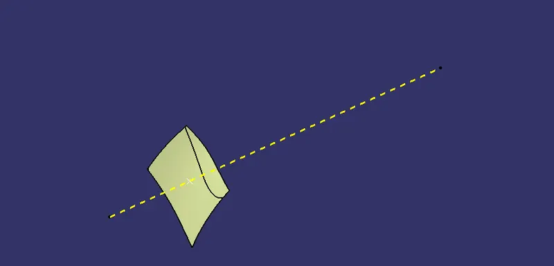
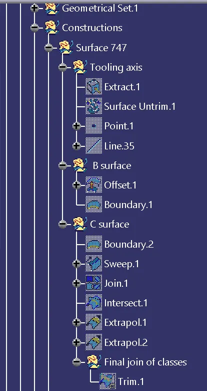
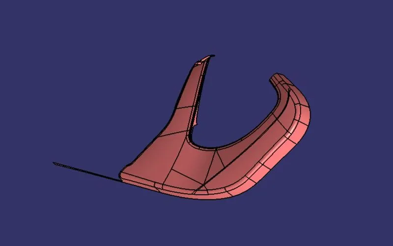
Extract a surface from the given Class-A surface of lower substrate and untrim the surface. Now create a point with reference to the surface and create a line passing through the point with respect to the surface, and it is our tooling axis for the lower substrate.
Class-B surface:
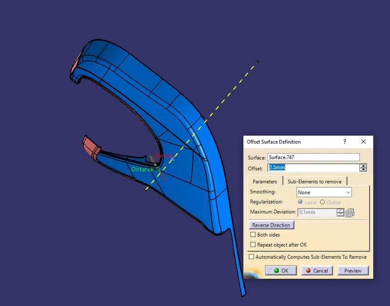
Check the Class-A surface whether the surface contains any errors by using boundary tool and create a boundary for the Class A surface. If there are no errors found, Then offset the Class-A surface. This is our Class-B surface.
Class-C surface:
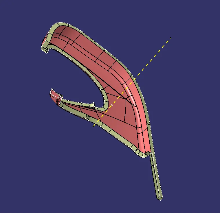
Extract the boundary from the Class-A surface and create the Class-C surface using sweep tool and sweep the surface at an angle of 90 degrees with respect to the surface. Now join the Class-A and Class-C surfaces.
Close surface:
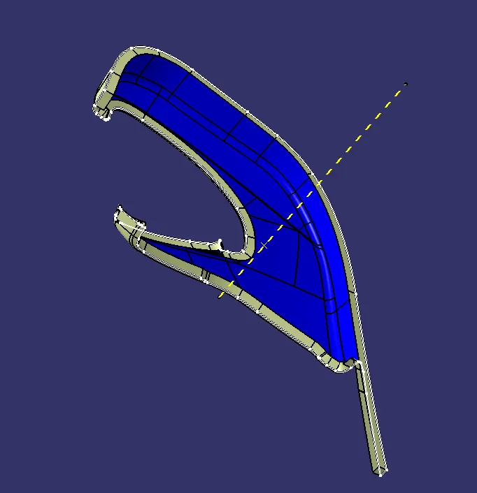
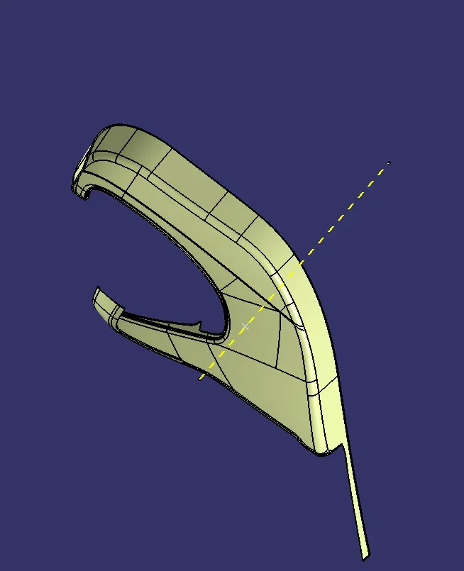
Trim the B surface from the join of Class-A and Class-C surfaces, This is the close surface output for making the solid part. Using close surface tool from part design created the solid part of the lower substrate.
Heat stakes with 4-way locators:
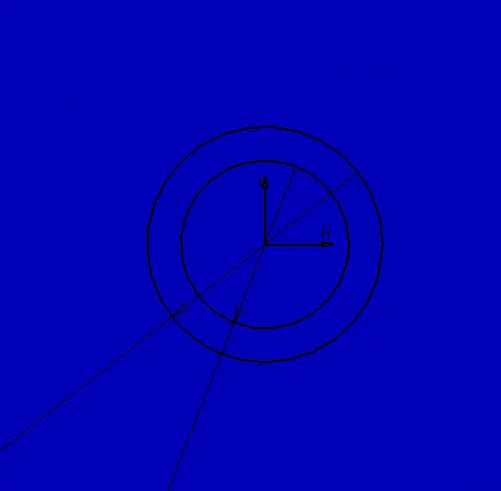
Sketch of heatstakes
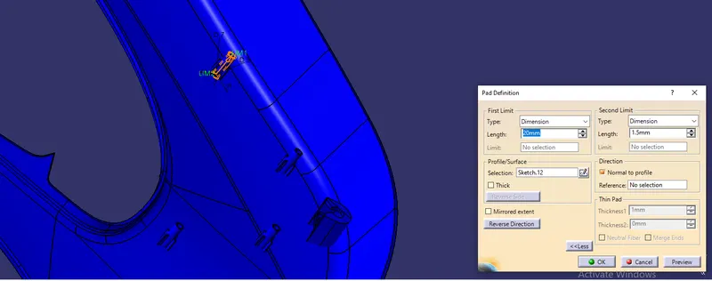
Padding the heatstakes
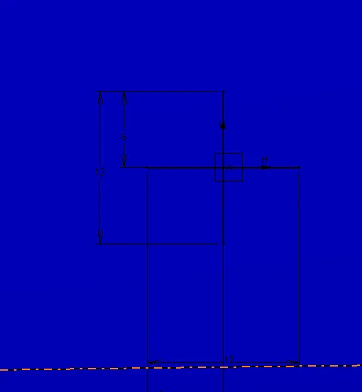
sketch of 4-way locator
Padding of 4-way locator
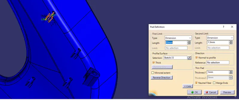
Create a plane with respect to the surface and go to the positioned sketch to create the heat stakes sketch on that plane, Now go to the part workbench to create heat stakes using pad tool. Now draw the sketch of the 4-way locators in the sketcher and pad the locators in part workbench. Now, using union trim in boolean operation, trim the unwanted surfaces and join the 4-way locators and the heat stakes. Repeat the same boolean operation and join the solid lower substrate and the heat stakes with 4-way locators.
Dog Houses:
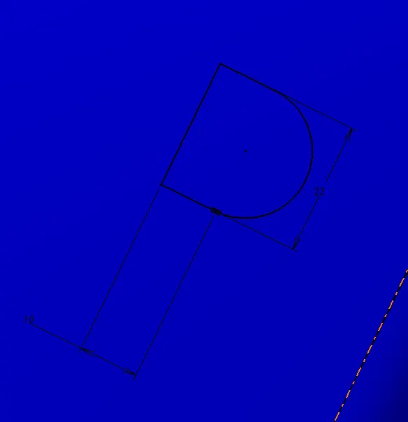
sketch of dog house
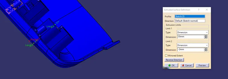
extrude operation
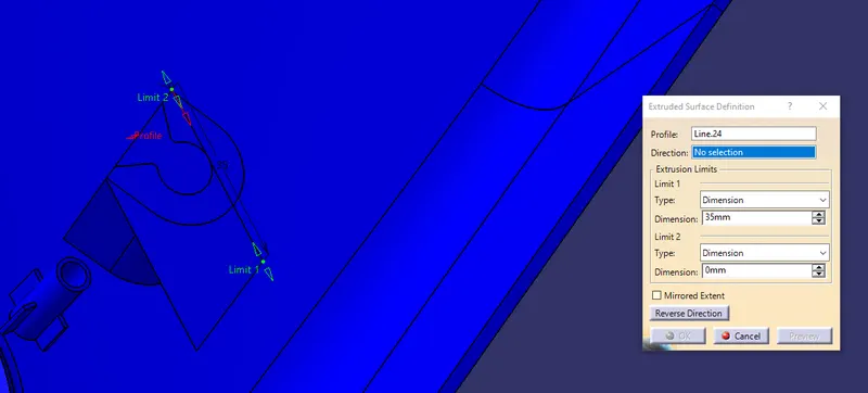
trim the extruded surfaces
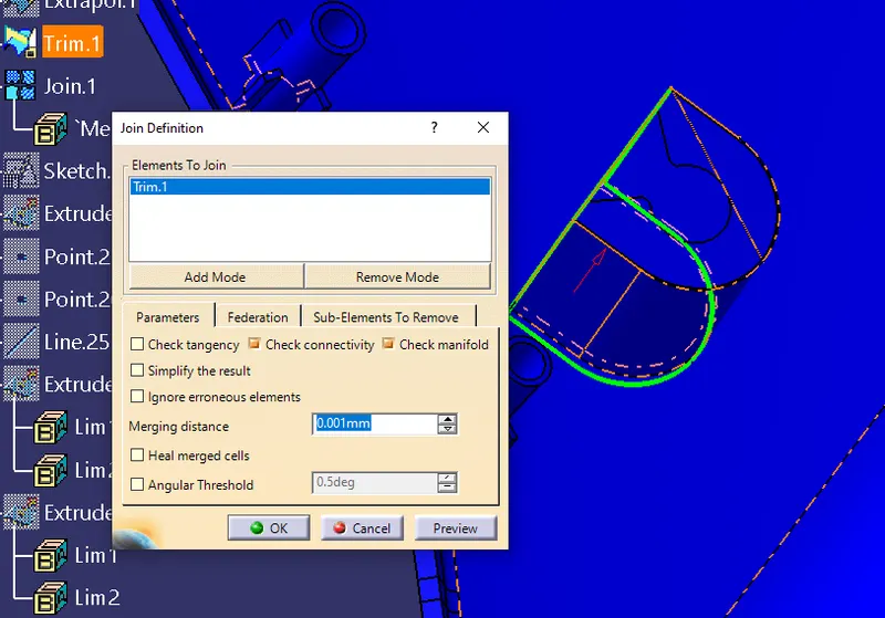
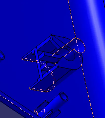
creating surfaces
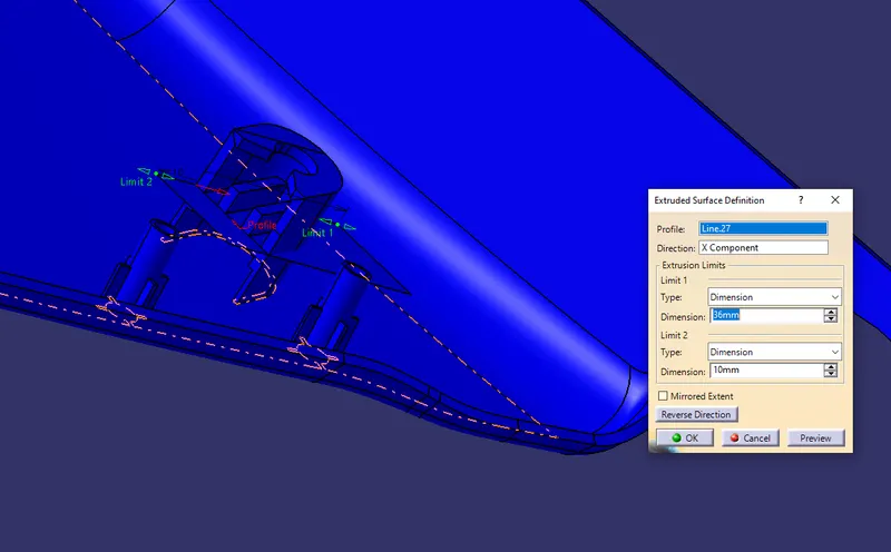
offset of outer dog house surface
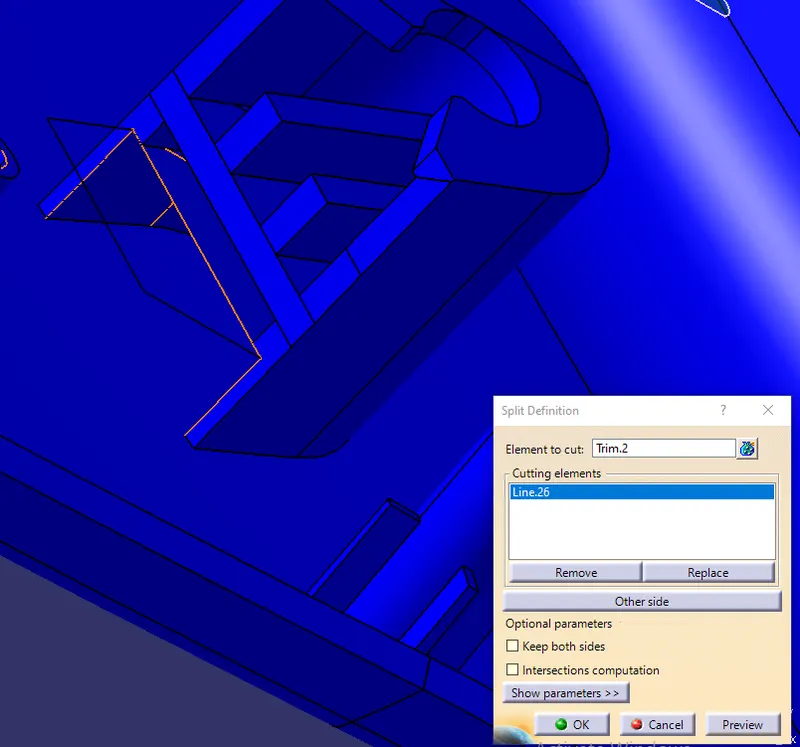
Ribs creation
transfering the duplicate objects in different position
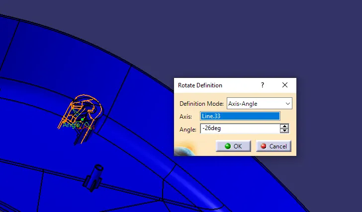
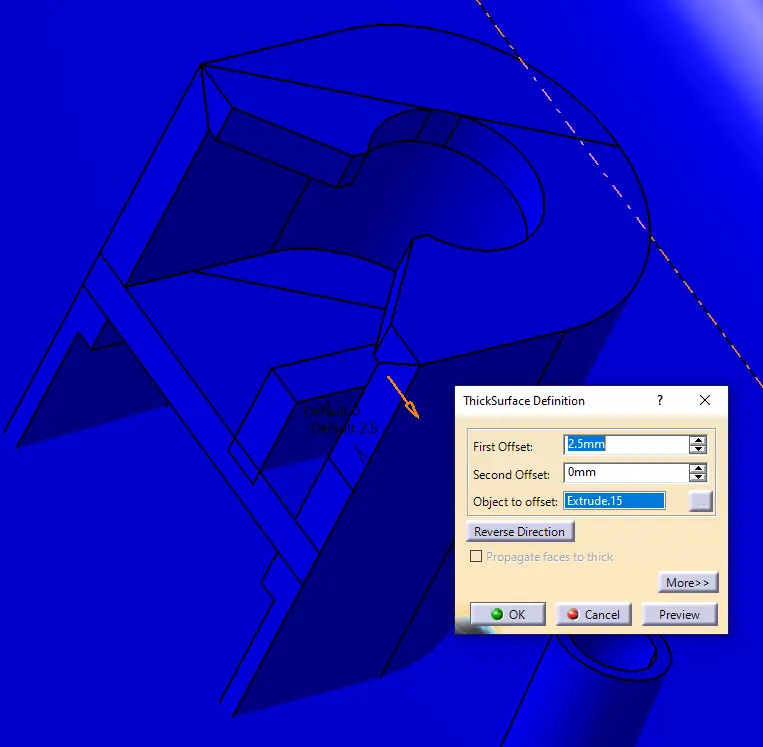
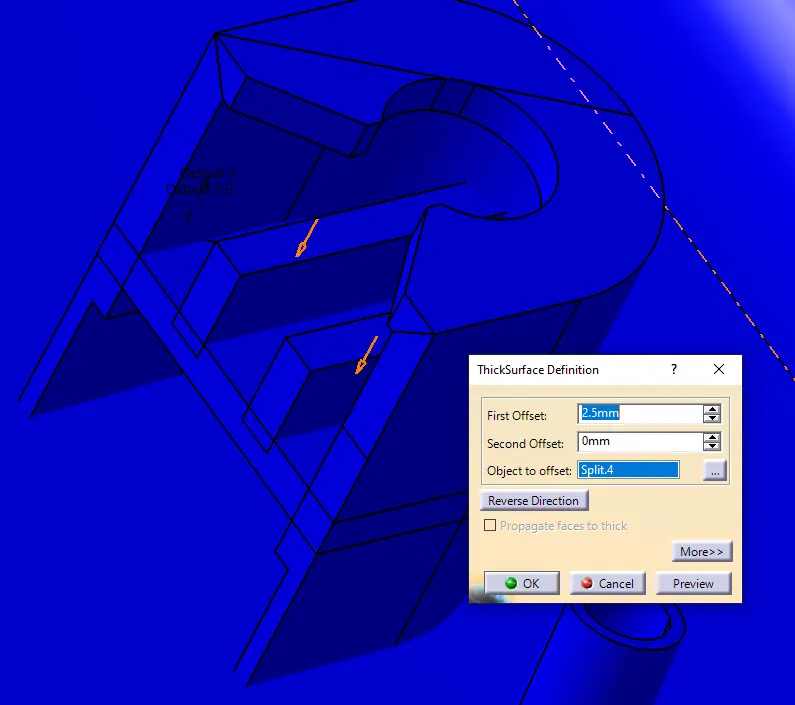
Create a point with reference to the surface and create a plane with reference to surface and the point. Now draw a sketch of the dog house and by using extrude tool create the surface now taking two points as a reference create a line and extrude the surface. Trim the extruded surfaces and draw a sketch for the sitting of the pushpins on the dog house and create the surface for the sketch. Now trim the surfaces and thicken the surface with the help of thickening surface tool in the part workbench. Now offset the surface of the dog house and create a line at center of the offsetted surface with reference to two points and extrude the surface. trim the extrude surface on the offset surface. Using split trim the offset set from the solid part of dog house. Now create a horizontal line at the middle of the dog house on front plane and create a surface using extrude and thicken the surface. Now draw two lines on the thicken surface towards x axis create the ribs and using assemble boolean operation join the ribs and the extruded surface. Using same boolean operation join the dog house and the extruded surface with ribs.
Output:
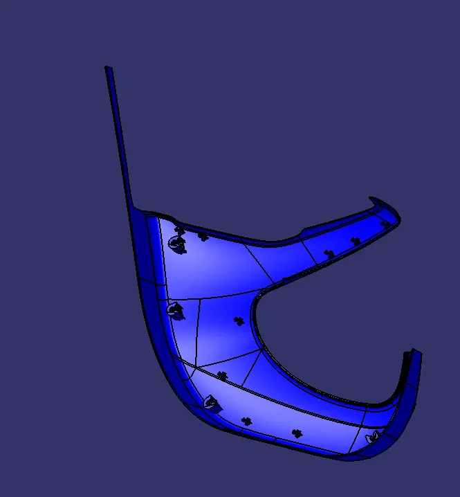
Draft analysis:
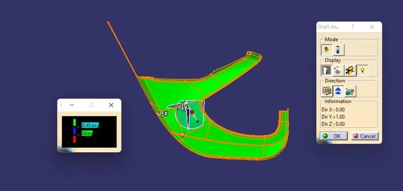
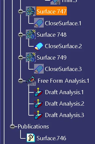
Perform draft analysis for the given Class-A surface.
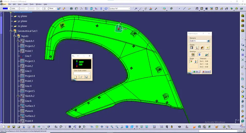
Perform draft analysis for the complete solid part.
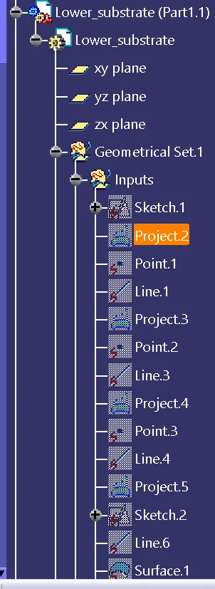
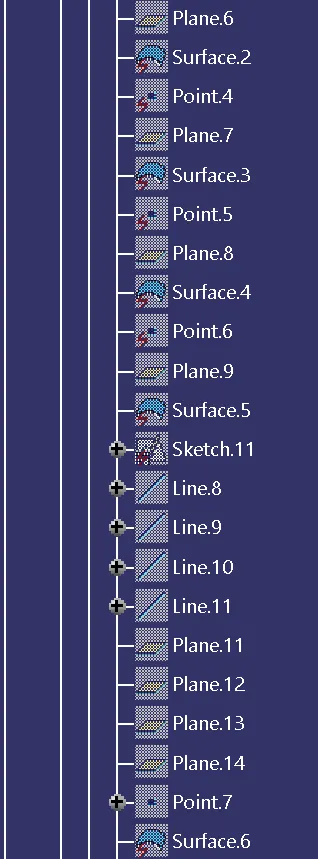
Tree:
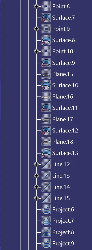
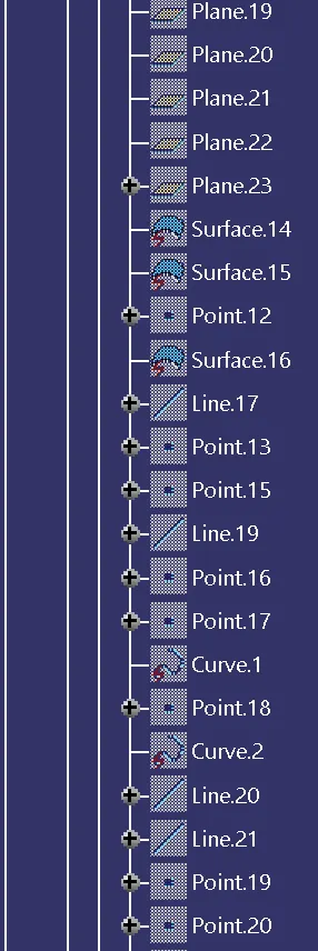
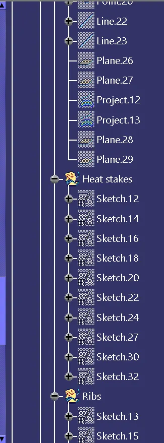
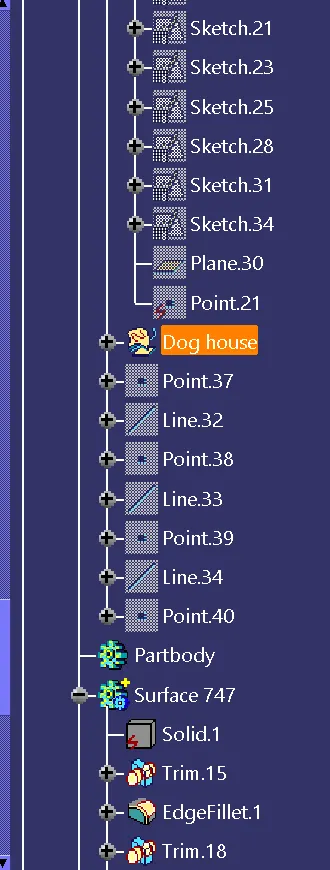
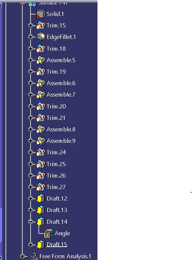
- Door arm rest:
Class-A surface:
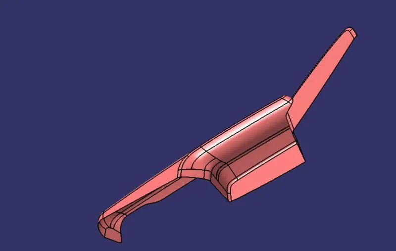
Tooling axis:
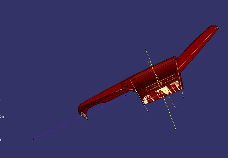
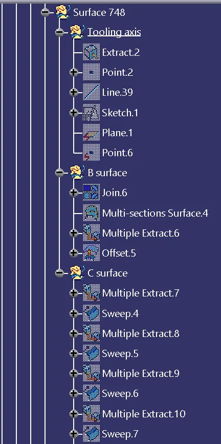
Extract a surface from the given Class-A surface of Door arm rest and untrim the surface. Now create a point with reference to the surface and create a bisecting line passing through the point with respect to the surface, and it is our tooling axis for the Door arm rest.
Class-B surface:
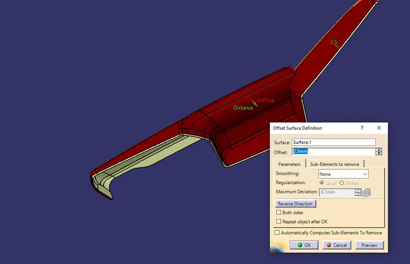
Check the Class-A surface whether the surface contains any errors by using boundary tool and create a boundary for the Class A surface. If there are no errors found, Then offset the Class-A surface. This is our Class-B surface.
Class-C surface:
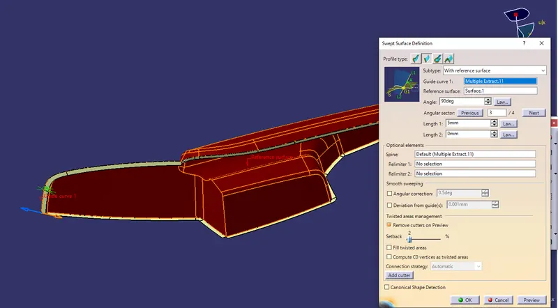
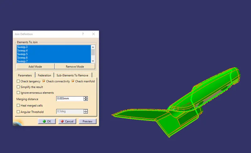
Extract the boundary from the Class-A surface and create the Class-C surface using sweep tool and sweep the surface at an angle of 90 degrees with respect to the surface. Now join the Class-A and Class-C surfaces.
Close surface:
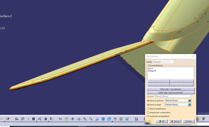
Trim the B surface from the join of Class-A and Class-C surfaces, This is the close surface output for making the solid part. Using close surface tool from part design created the solid part of the lower substrate.
Flanges:
creating surfaces using extrude
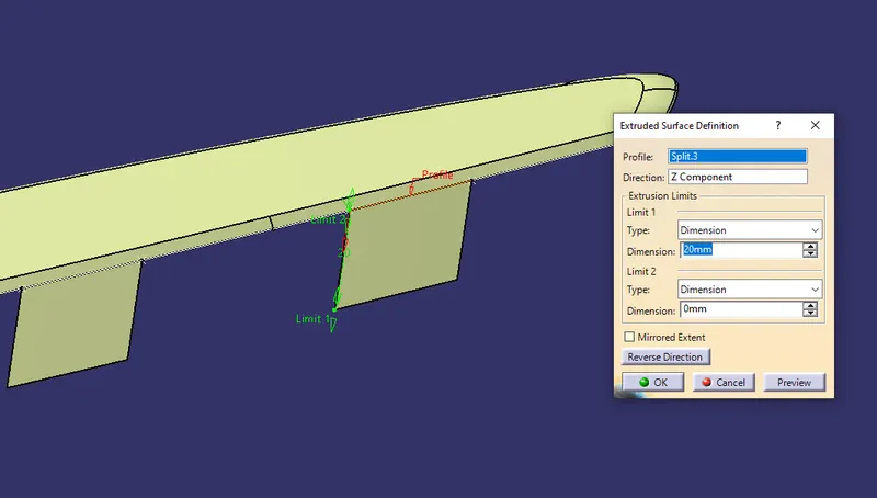
trimming the unwanted surfaces
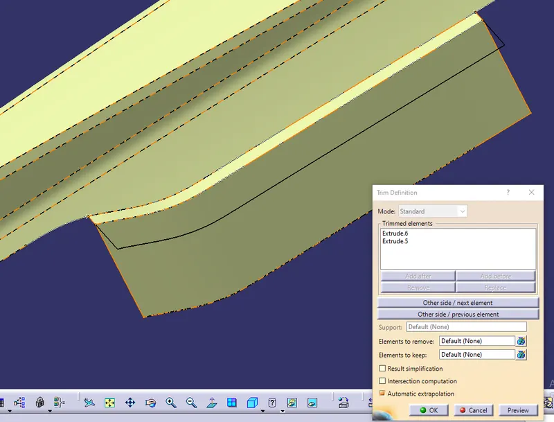
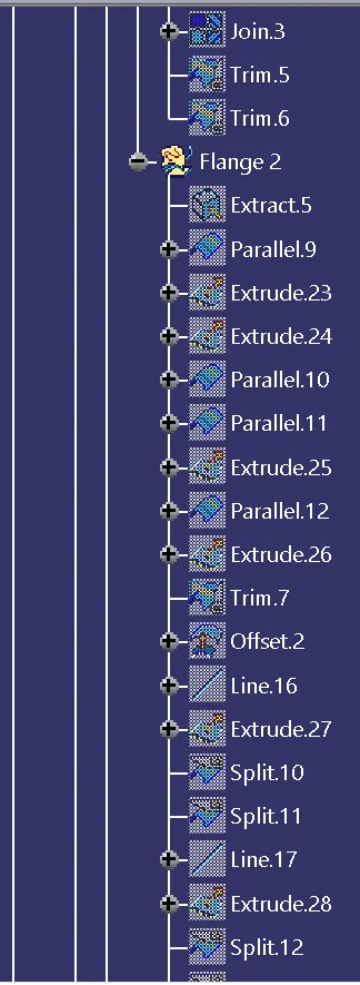
Extract the boundary from the surfaces and using parallel line create a parallel line to the boundary on the surface and extrude it with respect to X, Y, Z directions after creation of the surface for the flange offset it and draw a line and extrude the surface perpendicular to the flanges surfaces and trim the flange surfaces on both sides and front side. Now using close surface create a solidpart of the flanges. Using assemble boolean operation assemble the flanges to the solid part.
Heat stakes with 4-way locators:
sketch of heat stakes
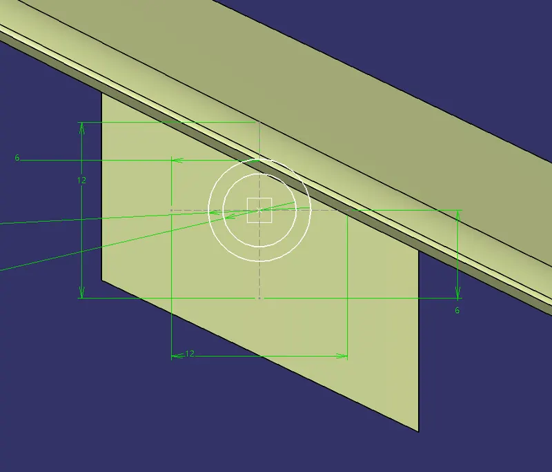
Padding the heatstakes
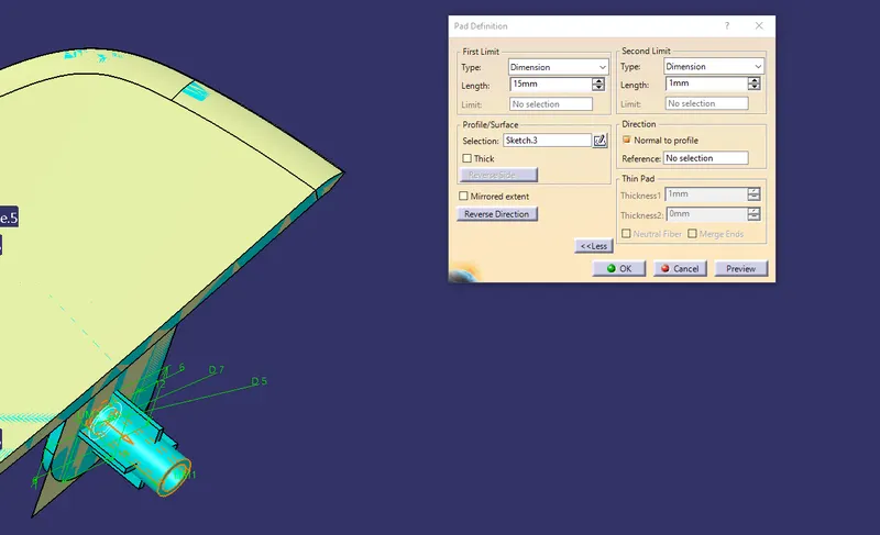
4-way locator sketch
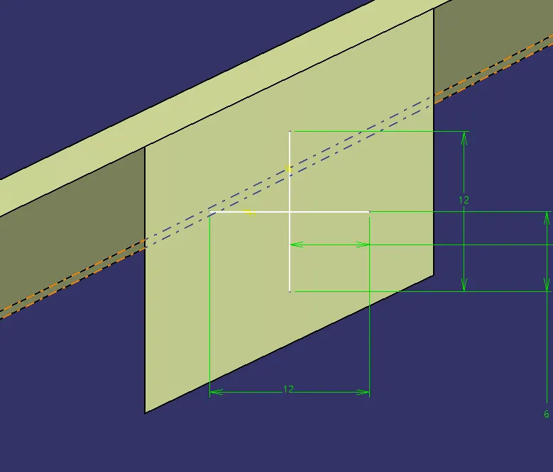
Padding the 4-way locator
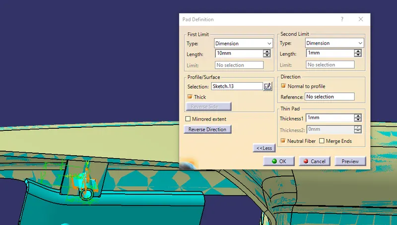
Create a plane with respect to the surface and go to the positioned sketch to create the heat stakes sketch on that plane, Now go to the part workbench to create heat stakes using pad tool. Now draw the sketch of the 4-way locators in the sketcher and pad the locators in part workbench. Now, using union trim in boolean operation, trim the unwanted surfaces and join the 4-way locators and the heat stakes. Repeat the same boolean operation and join the Flang and the heat stakes with 4-way locators.
Heat stakes hole:
Sketch for the heat stakes clearence on the flanges
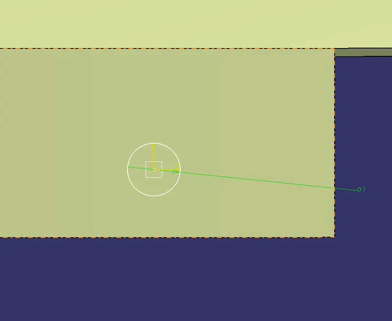
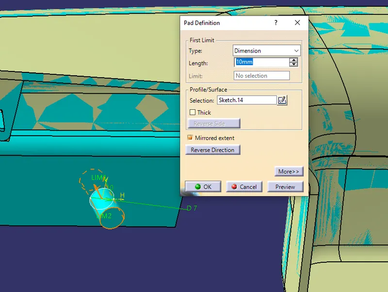
Create a plane with respect to the surface and go to the positioned sketch to create the heat stakes clearance hole sketch on that plane, Now go to the part workbench using pad tool extrude the sketch. Now using remove option in boolean operation make the hole on the solid part.
Output:
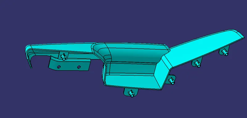
Draft analysis:
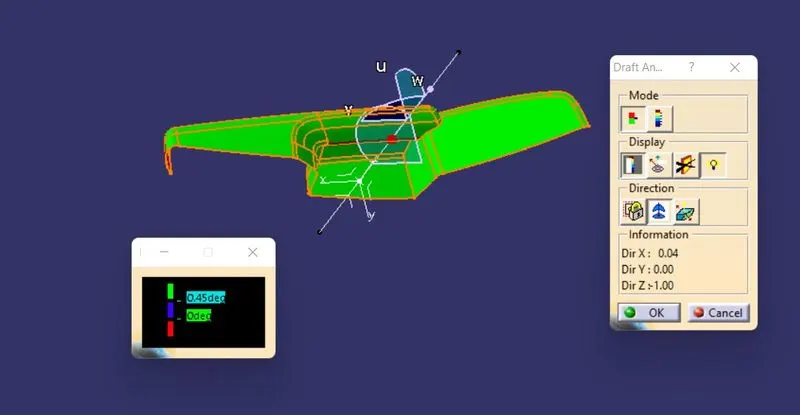
Perform draft analysis for the given Class-A surface.
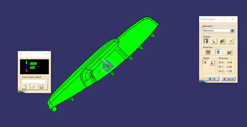
Perform draft analysis for the complete solid part.
Tree:
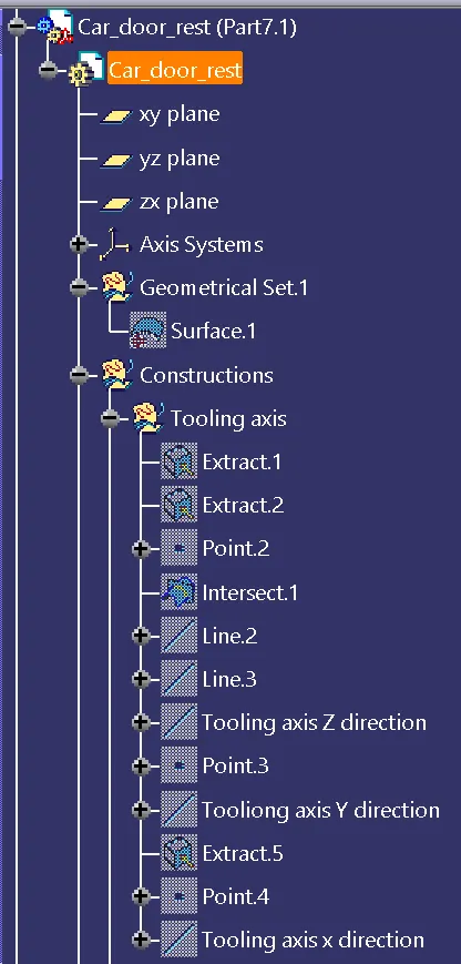
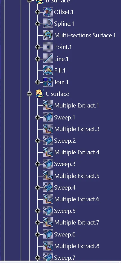
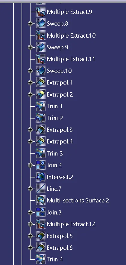
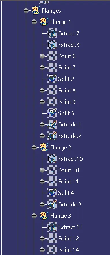
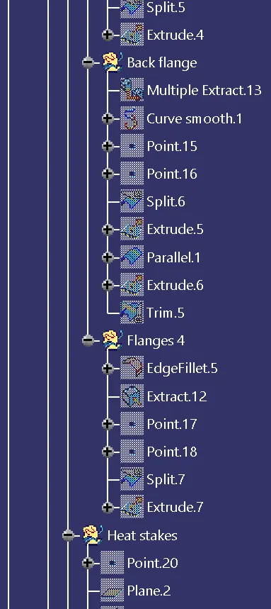
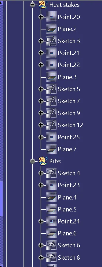
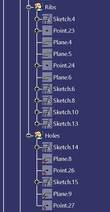
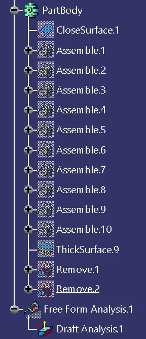
- Lower map pocket:
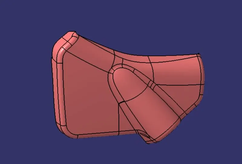
Class-A surface:
Tooling axis:
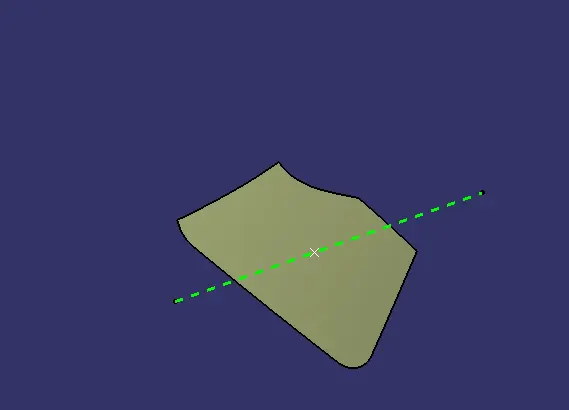
Extract a surface from the given Class-A surface of lower substrate and untrim the surface. Now create a point with reference to the surface and create a line passing through the point with respect to the surface, and it is our tooling axis for the lower map pocket.
Class-B surface:
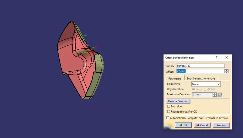
Check the Class-A surface whether the surface contains any errors by using boundary tool and create a boundary for the Class A surface. If there are no errors found, Then offset the Class-A surface. This is our Class-B surface.
Class-C surface:
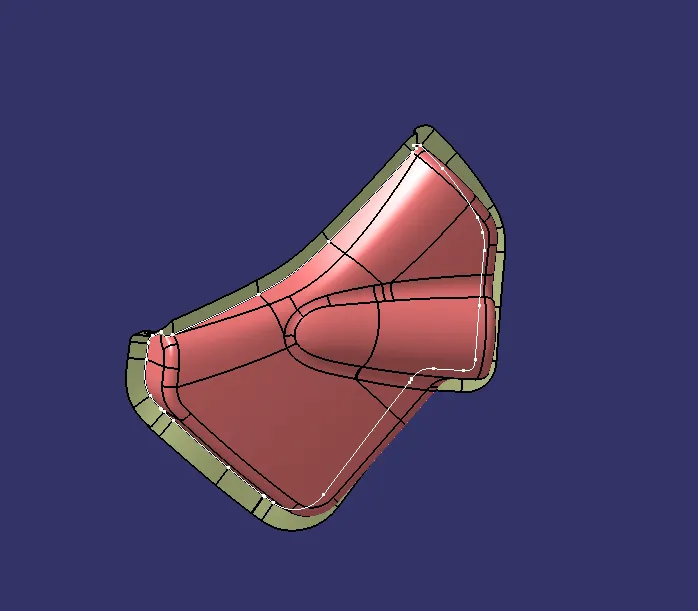
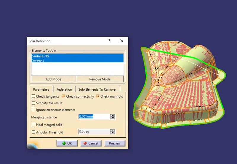
Extract the boundary from the Class-A surface and create the Class-C surface using sweep tool and sweep the surface at an angle of 90 degrees with respect to the surface. Now join the Class-A and Class-C surfaces.
Close surface:
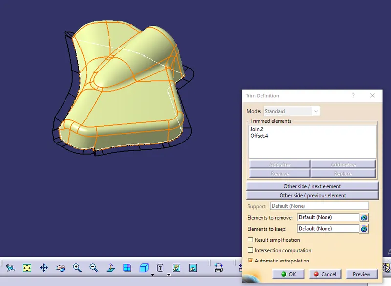
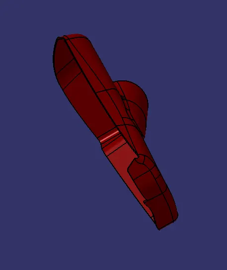
Trim the B surface from the join of Class-A and Class-C surfaces, This is the close surface output for making the solid part. Using close surface tool from part design created the solid part of the lower substrate.
Flanges:
Flange surface creation using extrude
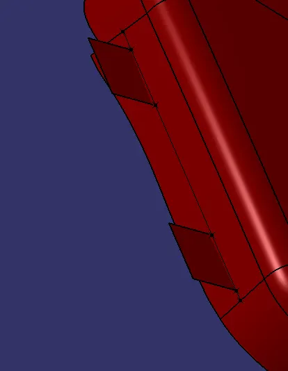
Thickening the flange surface
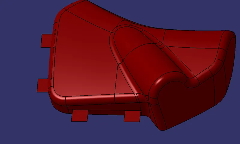
Extract the boundary from the surfaces and using parallel line create a parallel line to the boundary on the surface and extrude it with respect to X, Y, Z directions after creation of the surface for the flange offset it and draw a line and extrude the surface perpendicular to the flanges surfaces and trim the flange surfaces on both sides and front side. Now using close surface create a solidpart of the flanges.
Heat stakes hole:
Heat stake clearence hole sketch
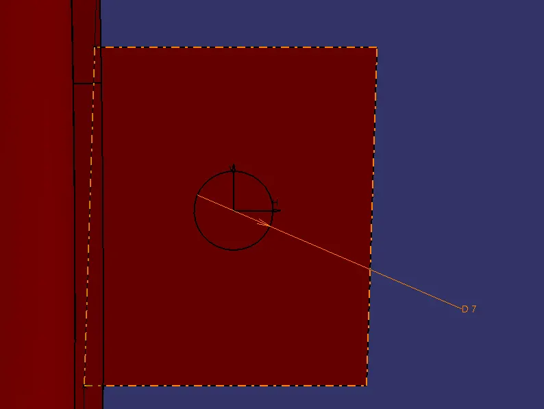
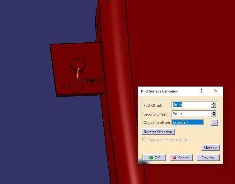
Create a plane with respect to the surface and go to the positioned sketch to create the heat stakes clearance hole sketch on that plane, Now go to the part workbench using pad tool extrude the sketch. Now using remove option in boolean operation make the hole on the solid part.
Output:
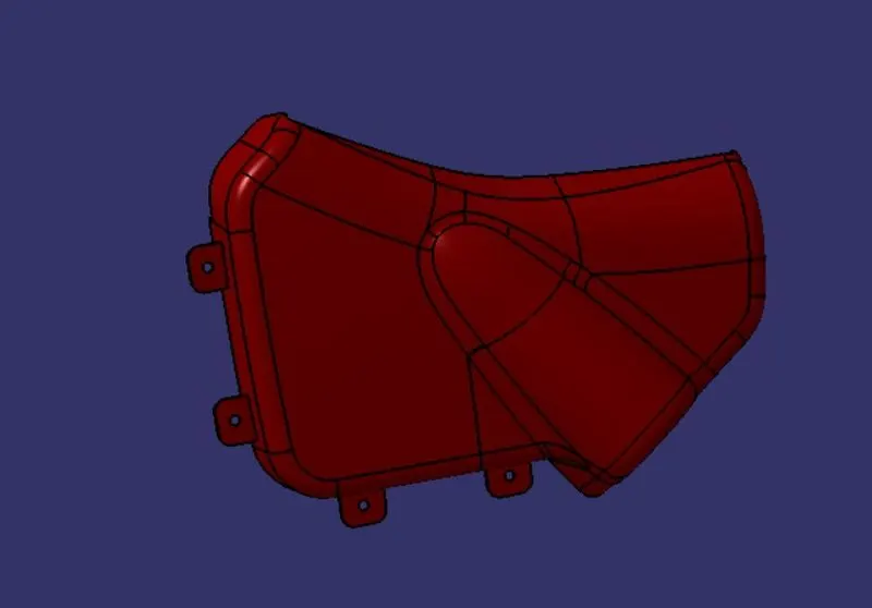
Draft analysis:
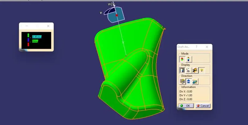
Perform draft analysis for the given Class-A surface.
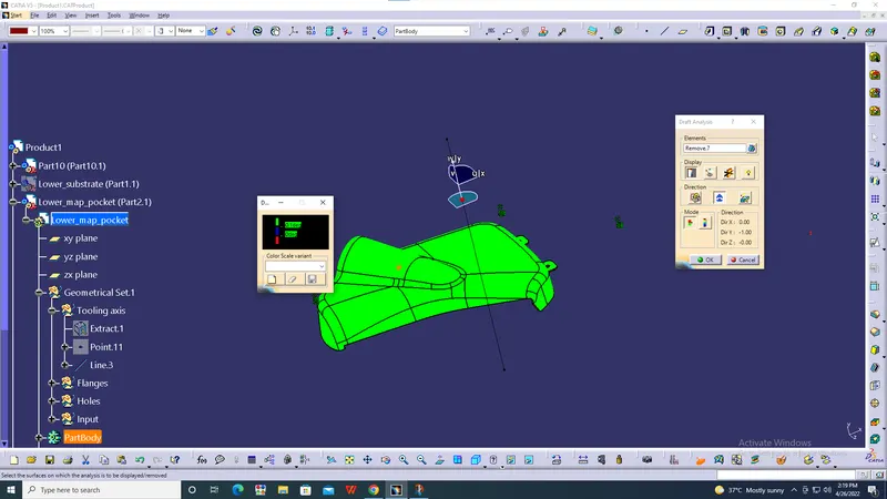
Perform draft analysis for the complete solid part.
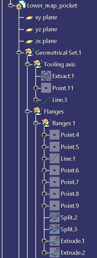
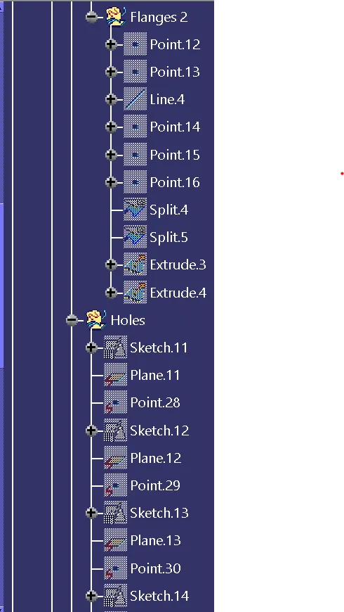
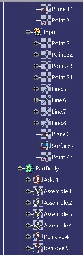
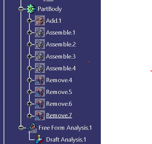
Tree:
- Upper map pocket:
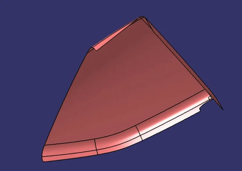
Class-A surface:
Tooling axis:
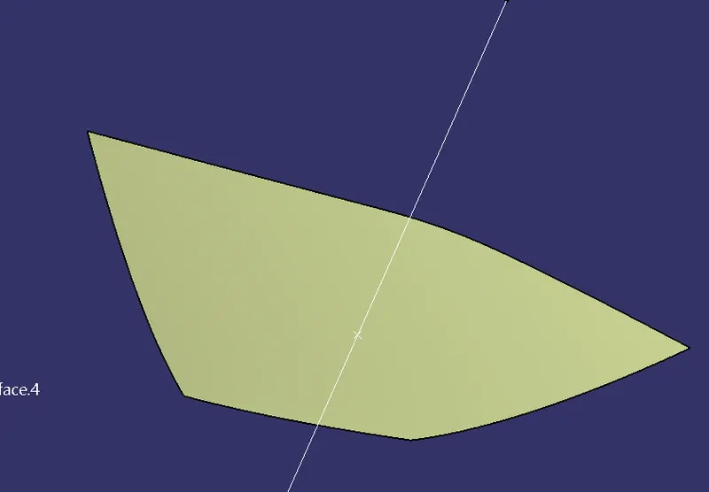
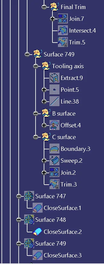
Extract a surface from the given Class-A surface of upper map pocket and untrim the surface. Now create a point with reference to the surface and create a line passing through the point with respect to the surface, and it is our tooling axis for the Upper map pocket.
Class-B surface:
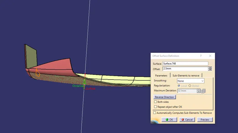
Check the Class-A surface whether the surface contains any errors by using boundary tool and create a boundary for the Class A surface. If there are no errors found, Then offset the Class-A surface. This is our Class-B surface.
Class-C surface:
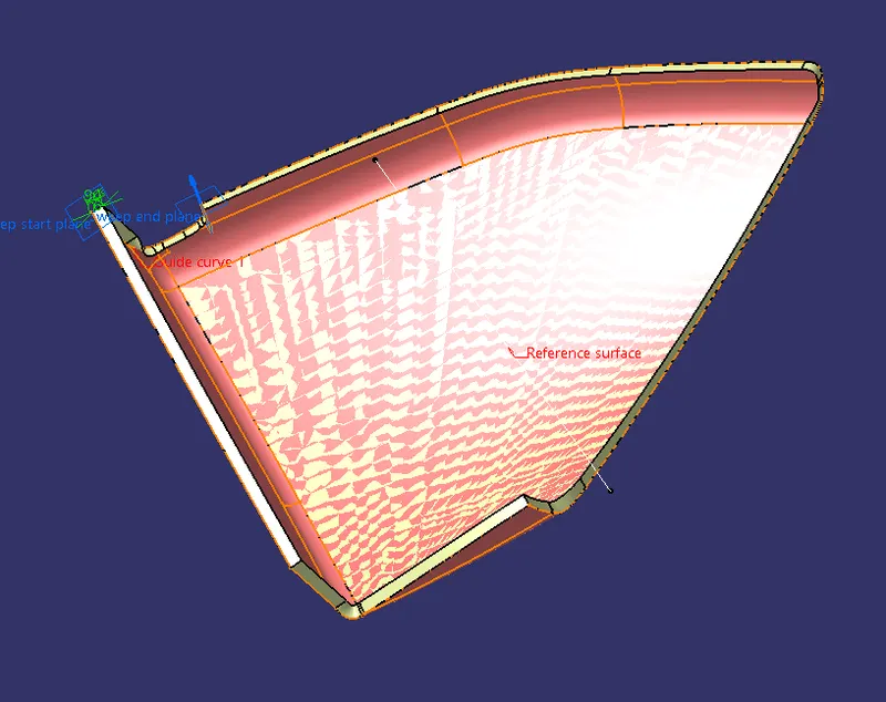
Extract the boundary from the Class-A surface and create the Class-C surface using sweep tool and sweep the surface at an angle of 90 degrees with respect to the surface. Now join the Class-A and Class-C surfaces.
Close surface:
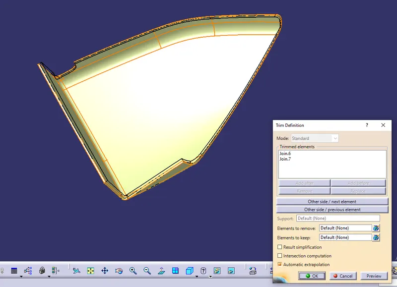
Trim the B surface from the join of Class-A and Class-C surfaces, This is the close surface output for making the solid part. Using close surface tool from part design created the solid part
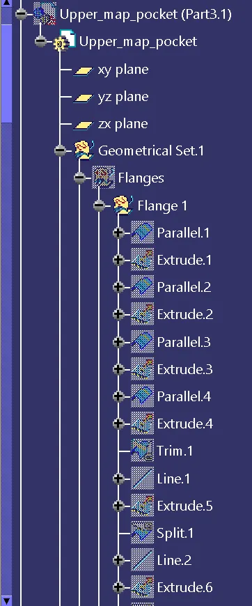
Flanges:
Flange surface creation
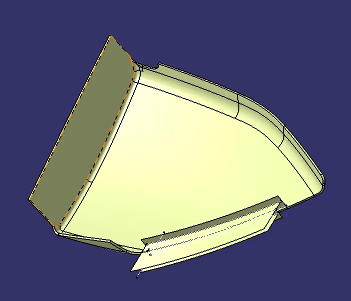
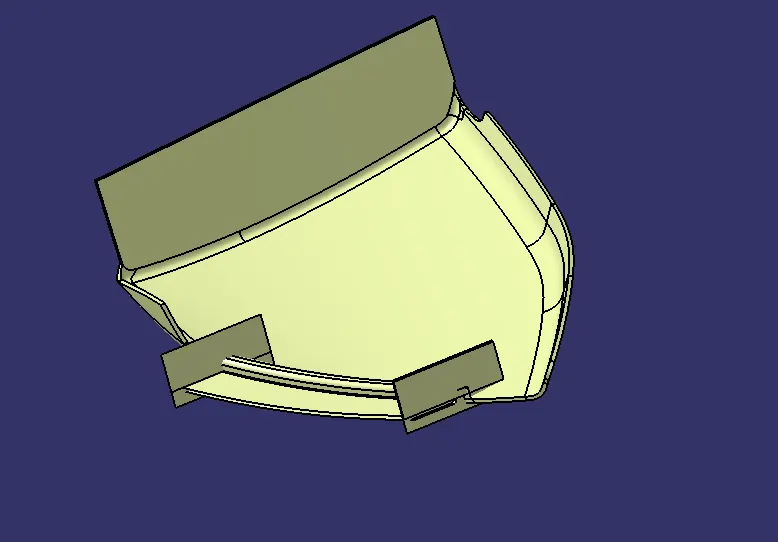
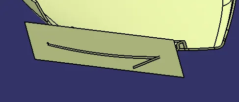
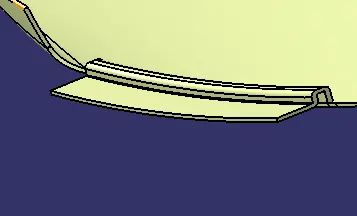
splitting the flange into 3 parts
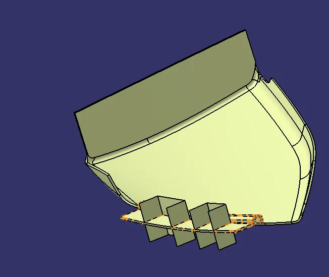
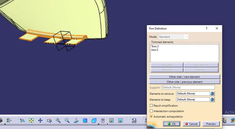
Side flange creation
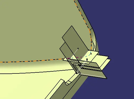
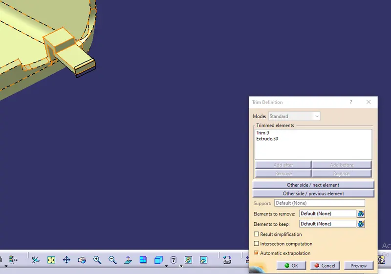
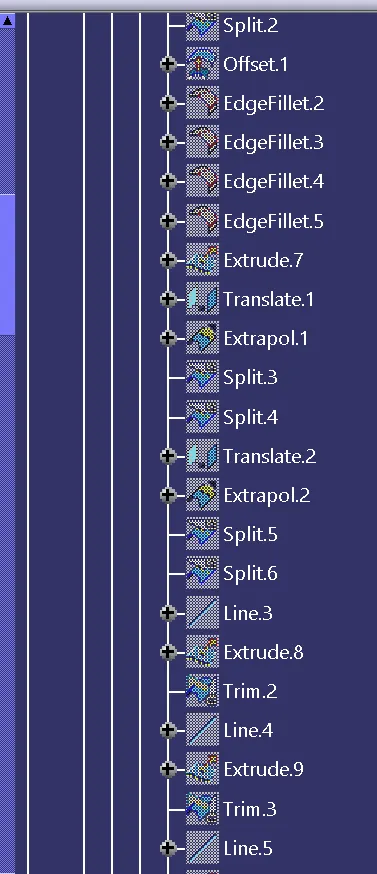
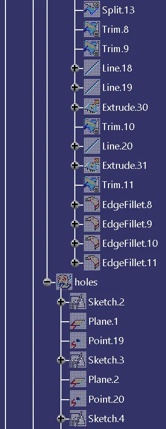
Extract the boundary from the surfaces and using parallel line create a parallel line to the boundary on the surface and extrude it with respect to X, Y, Z directions after creation of the surface for the flange offset it and draw a line and extrude the surface perpendicular to the flanges surfaces and trim the flange surfaces on both sides and front side. Now using close surface create a solidpart of the flanges.
Heat stakes holes:
Creating the heat stakes clearence hole on the flanges
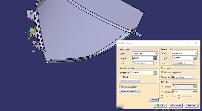
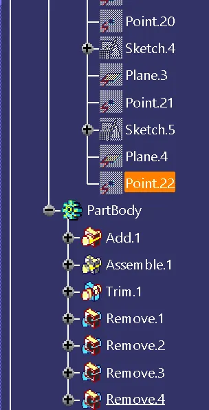
Create a plane with respect to the surface and go to the positioned sketch to create the heat stakes clearance hole sketch on that plane, Now go to the part workbench using pad tool extrude the sketch. Now using remove option in boolean operation make the hole on the solid part.
Output:
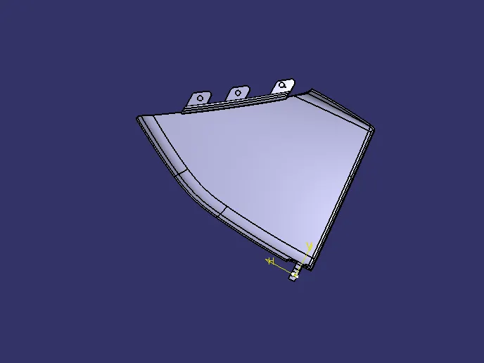
Draft analysis:
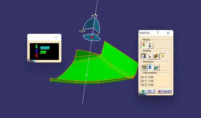
Perform draft analysis for the given Class-A surface.
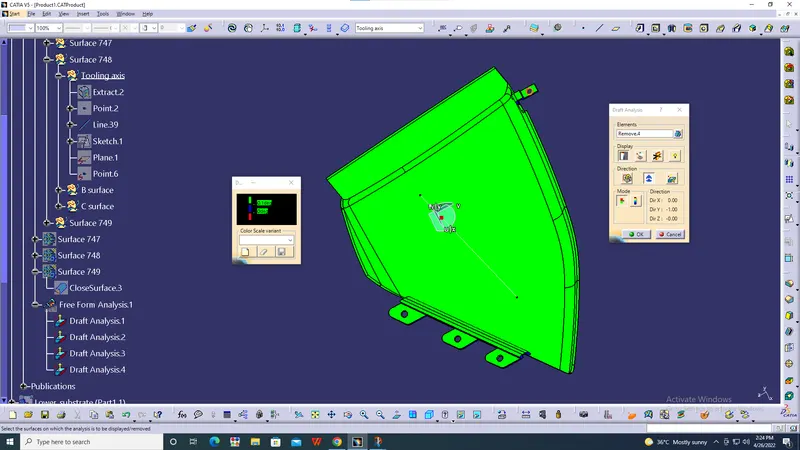
Perform draft analysis for the complete solid part.
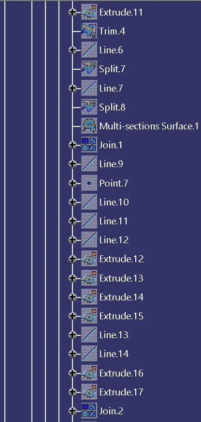
Tree:
- Pushpin:
- Assembly:
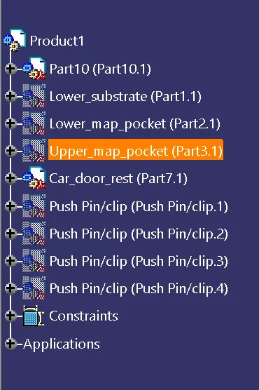
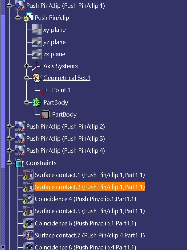
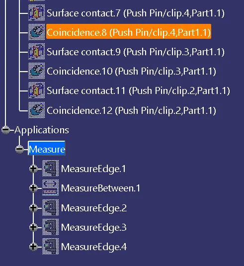
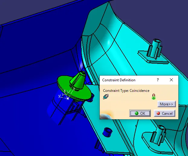
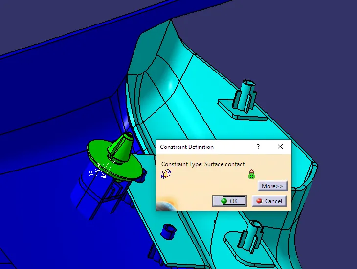
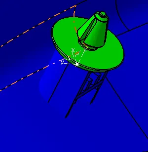
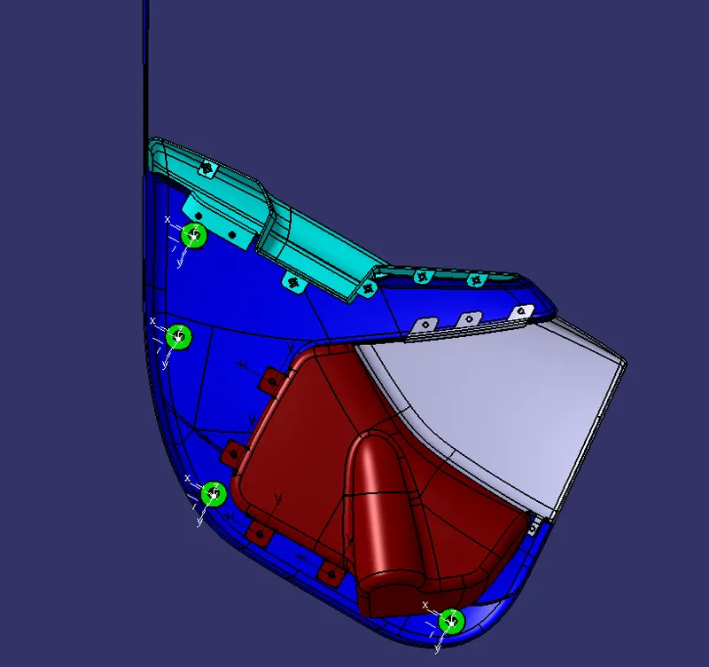
Using Coincidence and the contact surfaces constraints insert the pushpins in the Dog houses.
Output:
Tree: