Week 11 - Final project
AIM:To design and development of vehicle interior door trim using Catia v5 Tool using given Class A Surface and adding thickness to it.And also to create Ribs and Locators as per the given Master Section.
SUMMARY:
This project explain in brief regarding the Design life cycle followed in Automotive industry by working on practical Model CAR INTERIOR DOOR TRIM which is a Car interior trim part.In this report we have explain about the steps followed to create a solid body of the piller cover taking Class A Surface as input and creating a tooling axis and B surface with respect to the Class A Surface and creation of Class C Surface and also the Draft Analysis.The attachment features also designed and reported as per given Master Section considering all the design rules for the creation of Ribs and Doghouse.
WHAT IS MASTER SECTION?
Master Section are the guides for design requirement which decide the component packaging after technical (Styling,Concept or Class A) surfaces.
Following is the general workflow that is followed for the design and development of Interior and Exterior Automotive trims in OEM's
The styling and design teams at automotive OEM's always walk an extra mile to make the best looking interior and exterior automotive trims.But when it comes to Engineering for feasibility study,there are various constraints that are not well thought and analyzed due to time constraints.As a the best looking styling gets compromised in the production of vehicle.Above shown workflow the intial activity of styling and Class A Surface modelling is done by the clients and the rest of the activity is done by ASI with client representation at every stage of development.
To support OEM's overcome such challenge of delivering competitive and superlative quality automotive trims we have come up with a methodological approach that focuses on the major selling points of the vehicle.The approach is explained through following three steps
STEP-1: Class A Surface Engineering feasibility check and feedback
STEP-2: Matching concept design in detail.
STEP-3: Master sections,Detailed Design consideration,B-Surface Modelling,Supplier feedback and drawing release.
OVERVIEW OF DESIGN LIFE CYCLE:
- RESEARCH:
The research design refers to the overall strategy that you choose to integrate the different components of the study in a coherent and logical way,thereby,ensuring you will effectively address the research problem,it constitutes the blueprint for the collection,measurement and analysis data.
- DESIGN REQUIREMENT:
The design requirements for a product are based on the wants and needs of the intended customer.These wants and needs must be identified by the company making the product,and they are often communicated by the target customer in non technical and sometimes vague terms.
- FEASIBILITY:
In some cases,a feasibility study is carried out after which schedules,resource plans and estimate for the next phase are developed.The feasibility study is an evaluation and analysis of potential of a proposed project to support the process of decision making.It outlines and analyses alternatives or methods of achieving the desired outcome.The feasibility study helps to narrow the scope of the project to identify the best scenario.A feasibility report is generated following which post Feasibility Review is performed.
- CONCEPT GENERATION:
A concept study is often a phase of project planning that includes producing ideas and taking into account the pros and cons of implementing those ideas.This stage of a project is done to minimize the likehood of error,manage costs and evaluate the potential success of the intended project.In any event once an engineering issue or problem is defined,potential solutions must be identified,These solutions can be found using ideation the mental process by which ideas are generated.It can be done normally by clay modelling.
- PRELIMNARY CLASS A SURFACE DESIGN:
The preliminary design or high level design includes often bridges a gap between design conception and detailed design,particularly in cases where the level of conceptualization acheived during ideation is not sufficient for full evaluation.So in this task the overall system configuration is defined and Schematics,diagrams and layouts of the project may provide early project configuration.During detailed design and optimization,the parameters of the part being created will change,but the preliminary design focuses on creating the general framework to build the project on.This is also called as Class A Surface Design. Styling or A class surface are the terms used in plastic product design.That mean the surface of a component which is smooth or visible side to human eye after the part is assembled
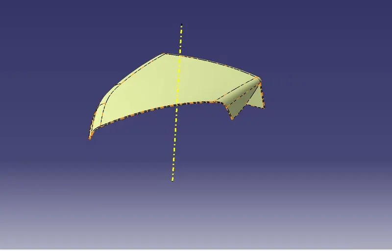
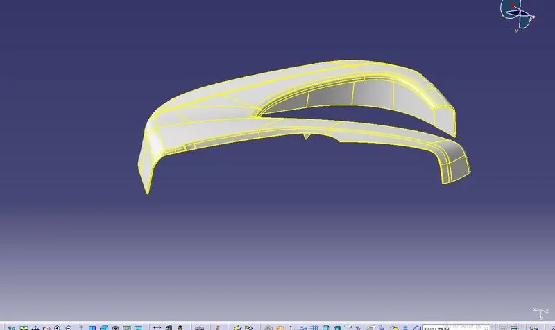
CLASS A SURFACE OF THE INTERIOR DOOR TRIM IS AS SHOWN IN PICTURE BELOW:
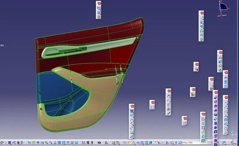
DESIGN OF INTERIOR DOOR TRIM:
Interior Door Trim consist of 4 major parts namely:
- Lower substrate
- Upper substrate
- Map pocket
- Door Arm Rest
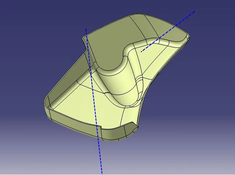
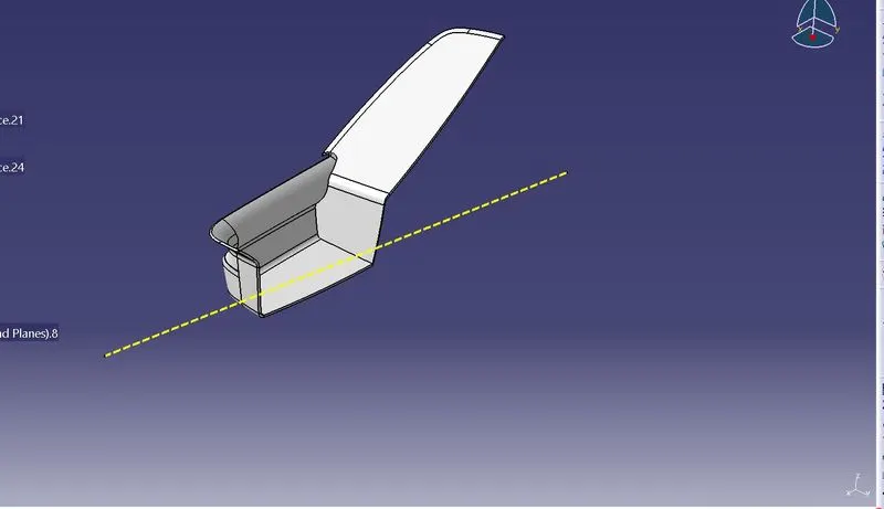
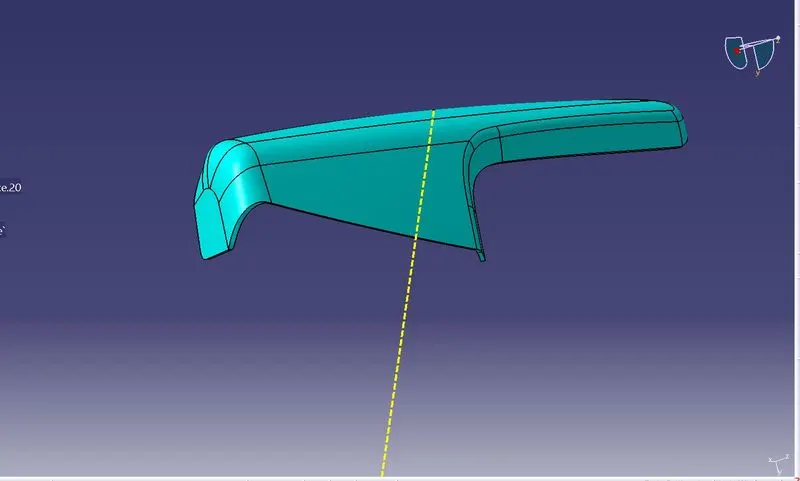
In this model we are designing only Lower substrate,Map pocket and Door Arm Rest and Attachment Features like Dog house and Heat stakes and doing Draft Analysis for all the component
- Designing of Lower Substrate,Arm Rest and Map pocket
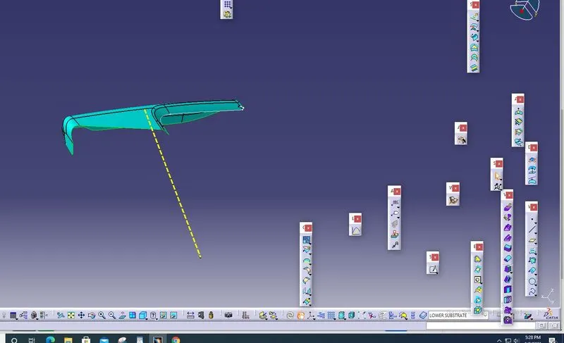
- CREATION OF TOOLING AXIS:
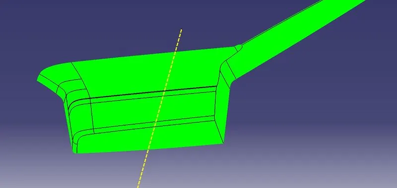
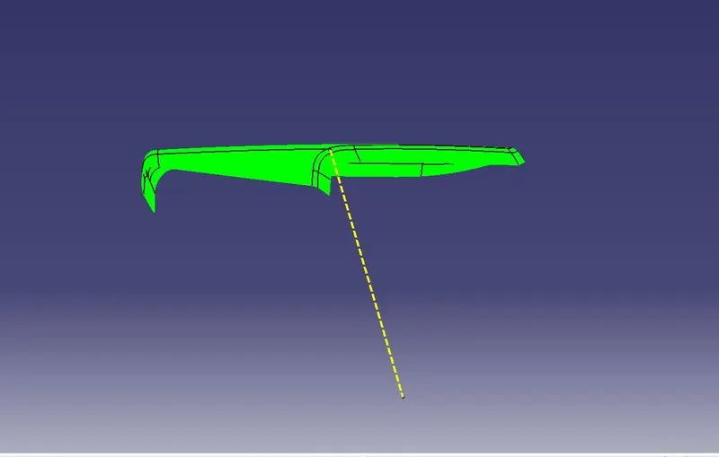
Tooling Axis is nothing but the direction in which the core and cavity opens and closes.Design Engineer work is to Analyse the Class A Surface and find out the best possible tooling direction keeping in mind all the Draft angle is with respect to the tooling axis so that the component can be easily ejected from the moulds.
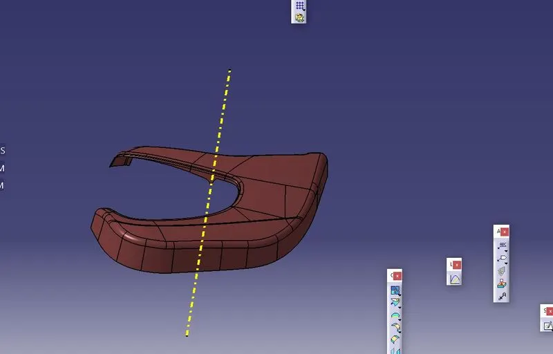
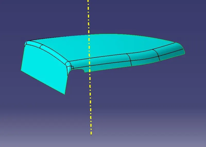
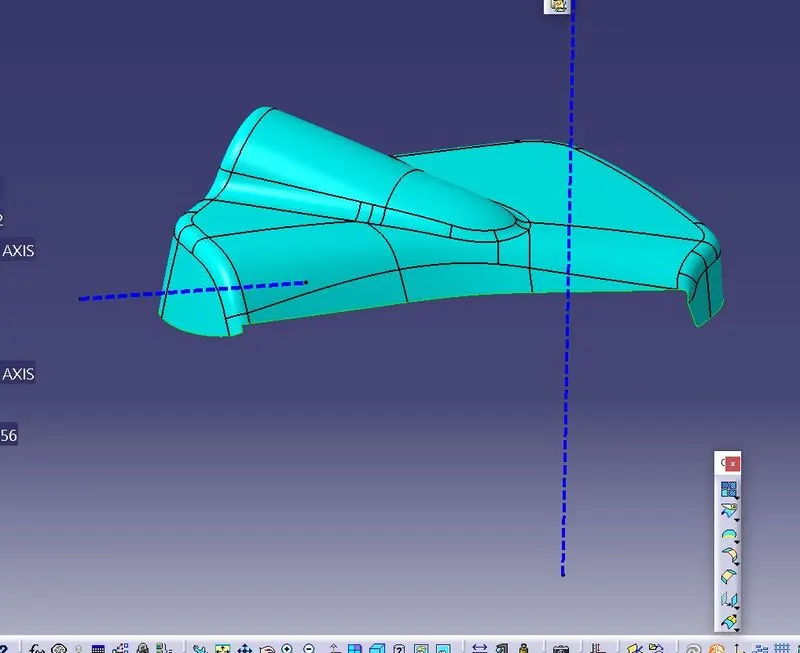

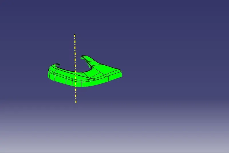
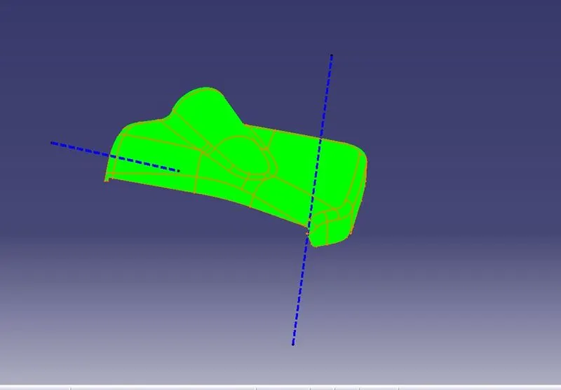
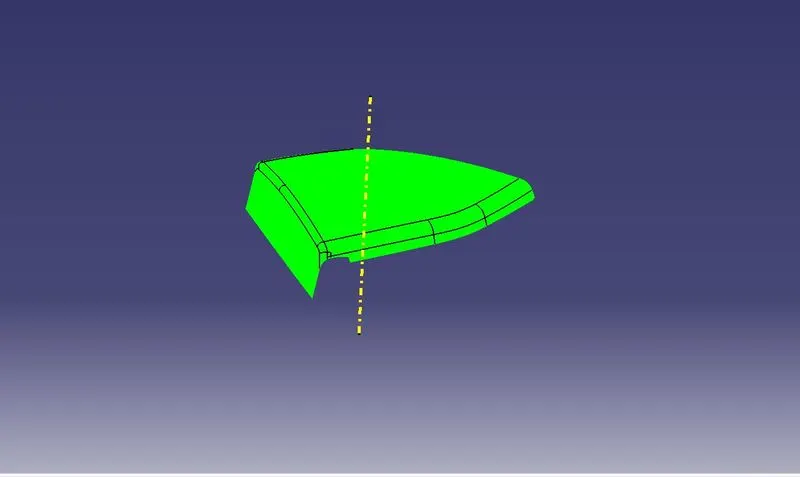
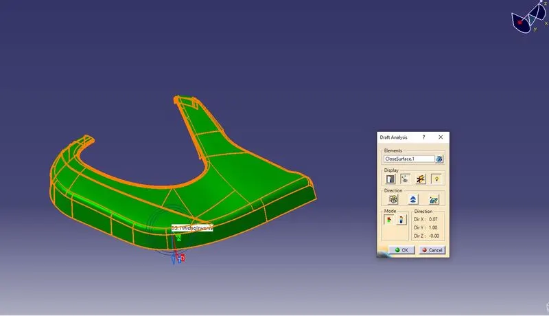
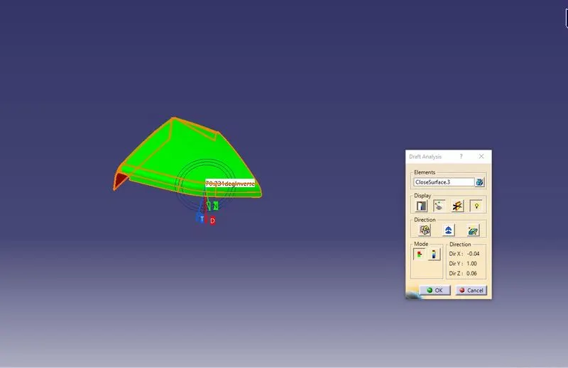
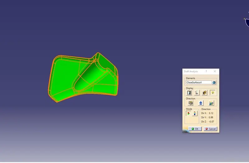
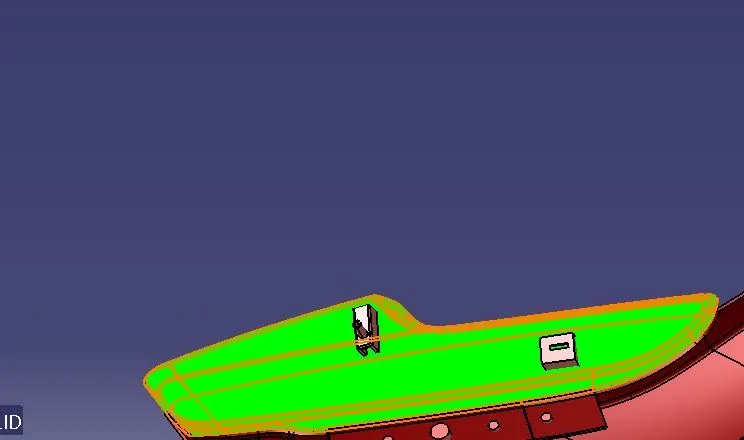
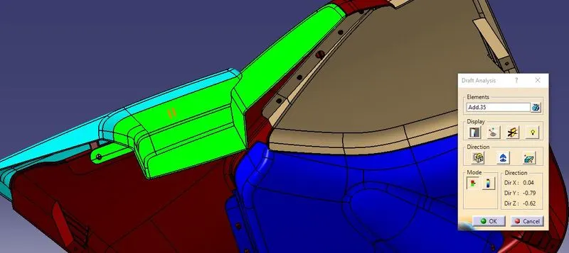
DRAFT ANALYSIS:
It is a tool that allows the user to see whether the part they are designing can be removed from the tool being used to make it.In the case of plastic injection molded parts it also allows the designer to see if there is enough draft on the part to ensure that it can be correctly grained.I always use the tool with the axis direction method.Put the main axis on the draft direction line with Z being parallel to it.Select the tool then select the part body.You may need to reposition the axis again.The result window has 2 option 1 with just 3 colour variants and the other with many variants.They can be edited by double clicking on them to give you the result you desire.The colours show the different draft angle
CLASS B SURFACE CREATION:
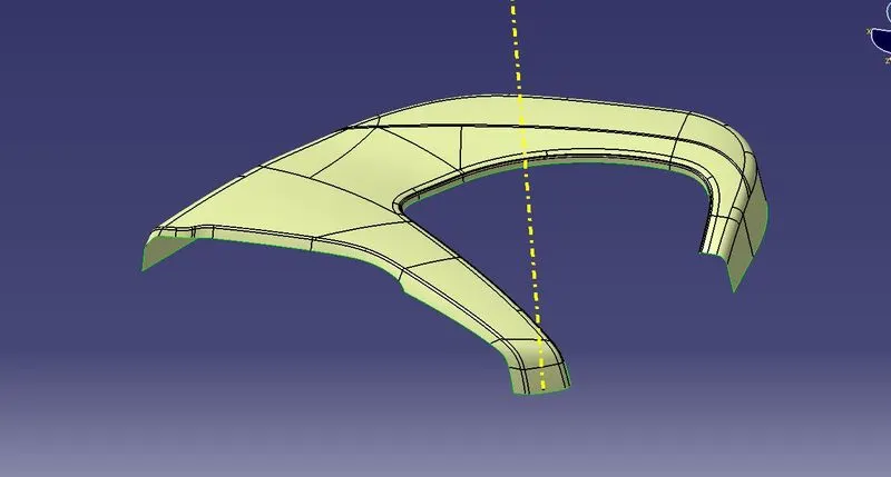
Once after getting the tooling Axis we need to create the B Surface which is parallel to the Class A Surface at the distance of the thickness of the component.It also includes the Each and Every edges,Fillets,features which is in the Class A Surface.In the Switch bezel the B surface are at the proportionate distance of 2.5mm from the Class A Surface.
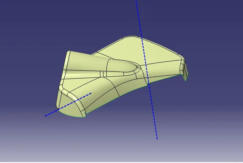
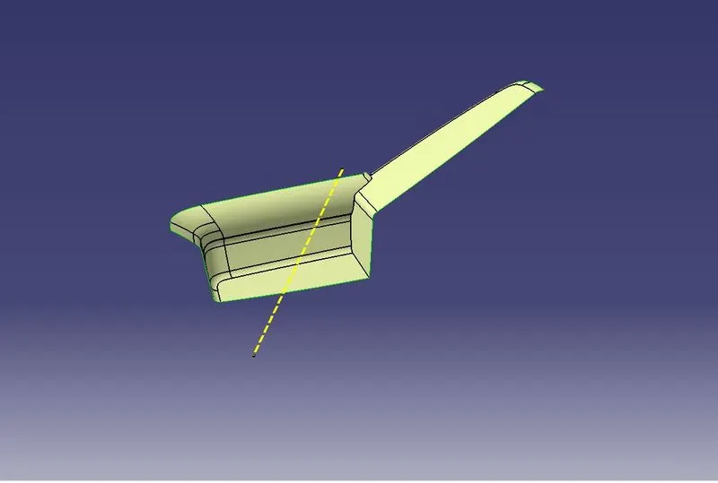
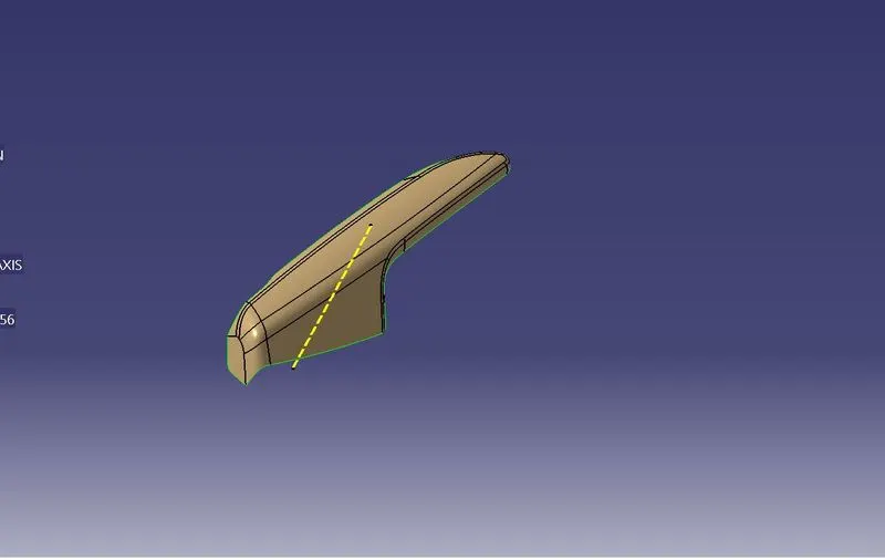
CLASS C SURFACE CREATION :
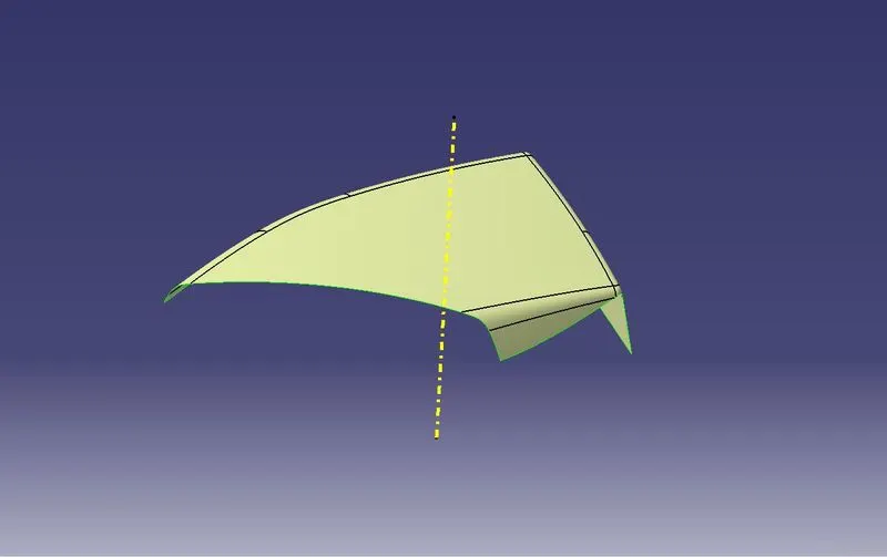
Class C Surface is swept along the boundary of the Class A at an angle perpendicular to the Class A Surface with respect to the Tooling Axis Direction with a Nominal Draft angle of 3 degree.
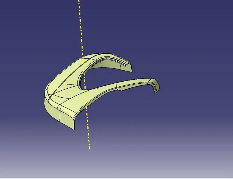
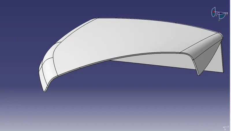
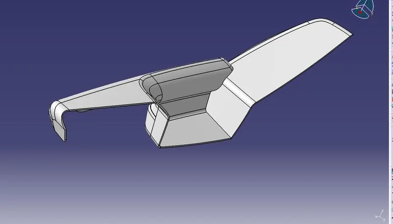
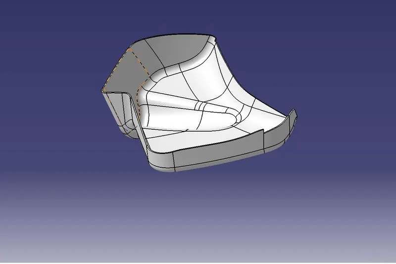
Once done with the generative sheet design switch to the part design and add thickness to the closed surface in order to get the closed volume
body as shown in the figure.
CREATION OF RIBS AND DOG HOUSE
Ribs provide economical stiffness and strength in molded parts without increasing overall wall thickness.They also facilitate
- Locating and arresting the components of an assembly
- Providing allignment in mating parts
- Actong as stops and guides for the mechanism
Proper rib design involves 5 main issues
- Thickness
- Height
- Location
- Quantity
- Manufacturability
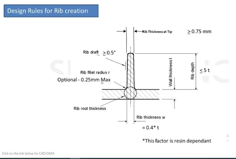
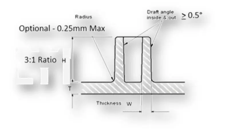
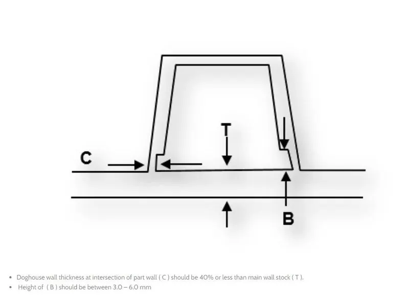
Considering the above displayed standard we have designed the ribs and Doghouse as per the master section provided
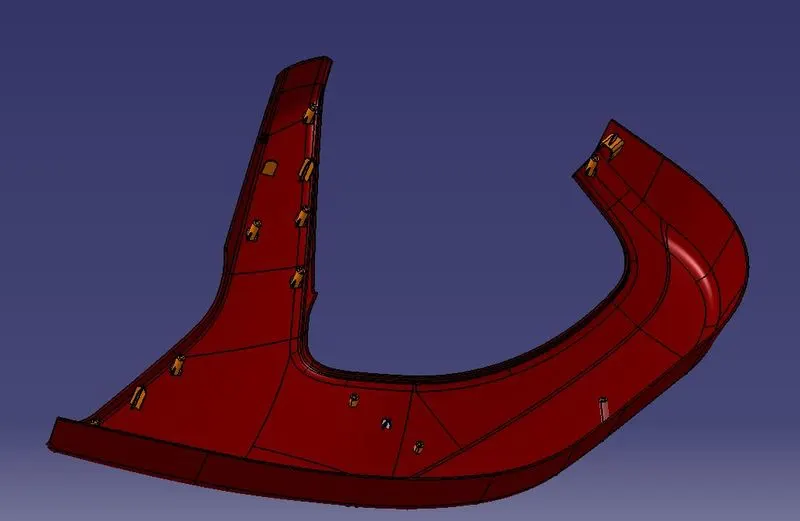
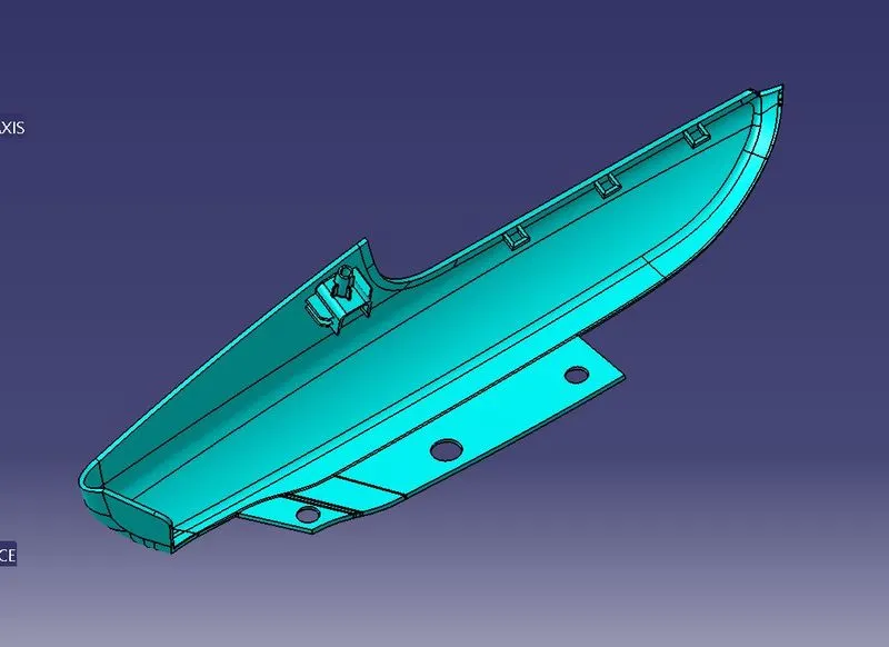
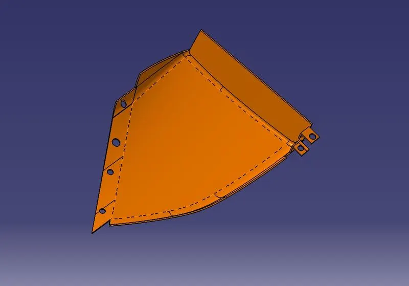
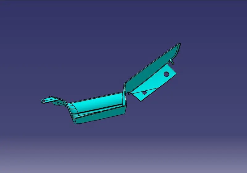
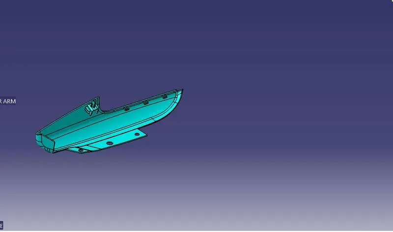
DRAFT ANALYSIS OF THE FINISHED COMPONENT
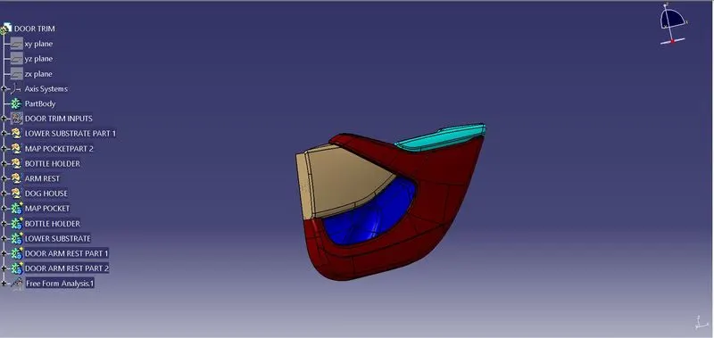
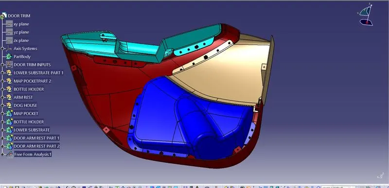
FINAL MODEL:
CONCLUSION:
Thus the Interior trim of the Car interior door trim is designed using the given Class A Surface as the Input and B and C class Surface are created with respect to the A Class surface.By using the Given Master Section attachment features that is Ribs, Doghouse,flanges and pushclips are created considering all the design rules for the creation of Ribs and Doghouse.Also carried out the Draft Analysis to check whether the component is easily manufacturable or not with the given draft of 3 Degrees for the surfaces and 0.5 degrees for the attachment features.With all these datas and report we can conclude that the Draft Analysis is very important to design any plastic Components because when we making a part that will be molded,the analysis will verify that all surfaces are favorable for being pulled from a cavity.It may also highlight or give insight to TROUBLE AREAS.