Week 11 - Final project
OBJECTIVE
Here I received class A surface of a car doors plastic trims. My objective is to develop the classA surface received into manufacturable product design following the OEM design standards using CATIA V5 surface workbench.
ABSTRACT
The project report deals with the steps and procedure followed while developing plastic trims for cars door from a class A surface provide,using CATIA V5 surface workbench. it explains the method I followed for crating the main tooling axis, side core axes, class B surface, class C surface and final closed body creations. it also explain the draft analysis performed to check the manufacturability of the product using injection moulding, various plastic door trims such aS map pocket,armrest,lowre substrate etc were successfully develop in this project.
PROCEDURE
CLASS A SURFACE
In automotive industry there will be a dedicated team who will perform the aesthetic designing of various components including the whole vehicle. They will creat various concept sketches after ideation.After that they will also create a class A surface of the product. This Class A surface is then passed over to the NPD CAD Team. They will initially inspect the class A surface in order to check if the design is manufacturable or if it is following the engineering principles. if there are any issues about the design, They will contact the product design team and will ask to modify the class A surface in order to solve the problem. Here I received the class A surface as show below.
DEVELOPMENT OF DOOR TRIM PANEL
INTRODUCTION
The Software I used For Developing The Solid Model in CATIA V5 CAD File Include All The Class A, Class B,Class C surfaces and Final Trim also a
Slid Model Of all The Components.
The CAD Part Incluse Solid Model Of The Following Components.
LOWER SUBSTRATE OF THE DOOR
DOOR ARM REST
MAP POCKET
INPUTS
The Inputs are given Class A Surface of The Complete Door Of The Along With Master Section Can Be Used as a Reference Marking For Flanges& Heatstakes.
CLASS A REFERENCE SURFACE OF DOOR WITH MASTER SECTION
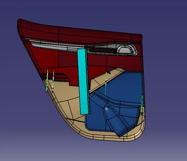
Reference A Class Surfaces Are Shown in Different Colour Which Include LowerSubstate,ArmRest,Map Pocket The Gree Lines are Master Section.
The Components developed for These Inputs
LOWER SUBSTRATE OF THE DOOR
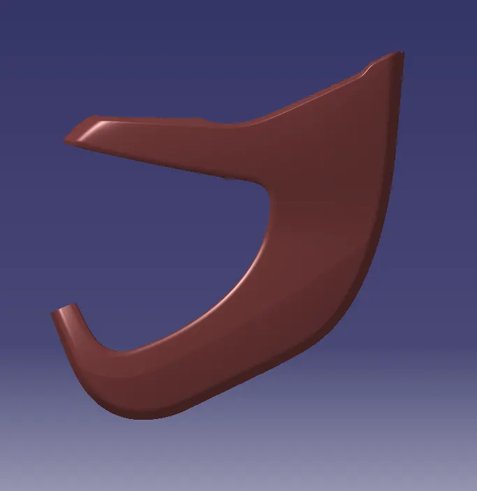
CLASS A SURFACE OF THE LOWER SUBSTRATE
The Class A Surface is Made By Using Join Command & Joining A Number Of Components From Reference Surface.

CLASS B SURFACE OF THE LOWER SUBSTRATE
The Class B Surface Is Same As the Class A Surface But It Should Be At An Offset Of 2.5mm From The Class A Surface
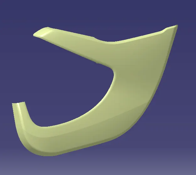
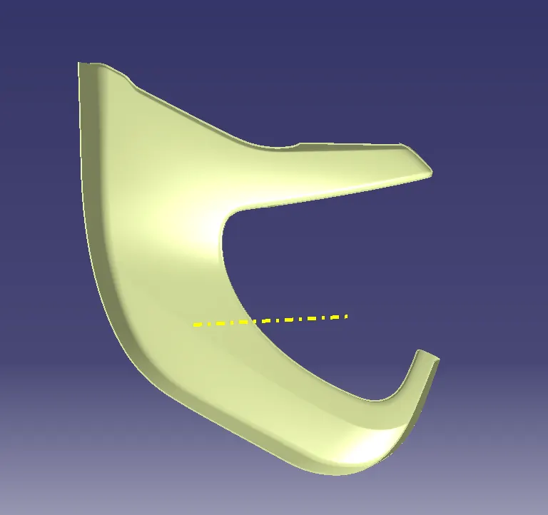
FINAL TRIM OF LOWER SUBSTRATE WITH CLASS A,CLASS B,CLASS C SURFACE ALONG WITH TOOLINGAXIS
This Final Trim Is made From Joining Or Trimming Class A,Class B,Class C Surface Class C Surfaces are made with Reference To Class A Surface
Using Sweep and Trim Commands.
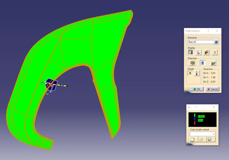
DRAFT ANALYSIS OF LOWER SUBSTRATE
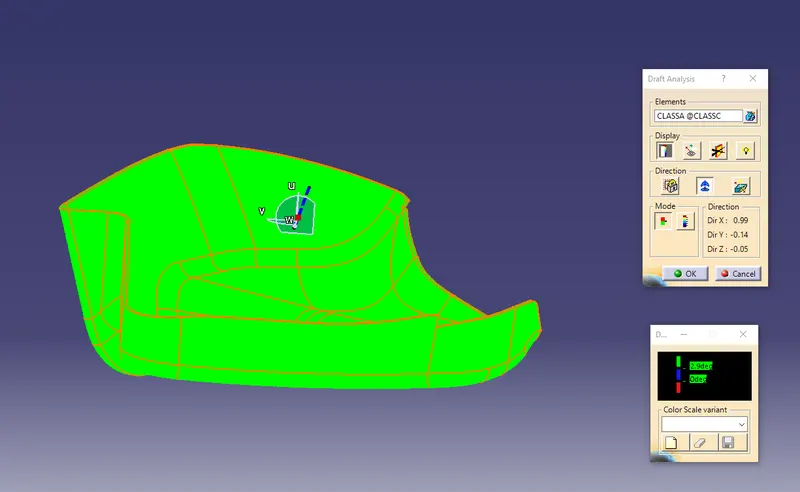
All Areas are Minimum Draft 2.9 deg As Shown In Picture.
SOLID MODEL OF LOWER SUBSTRATE
HEATSTAKES
DOG HOUSE
4 WAY LOCATOR
2 WAY LOCATOR
SNAPS
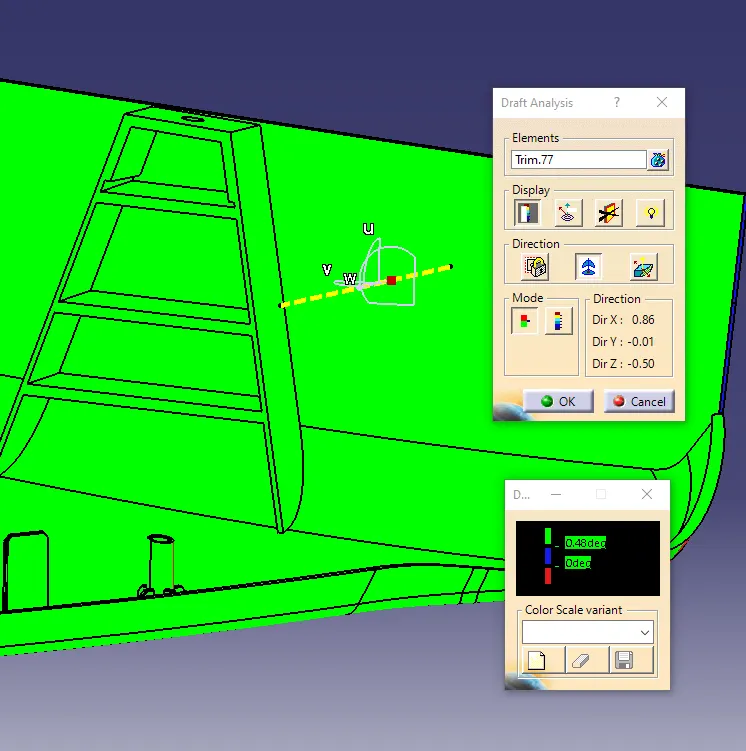
RIBS
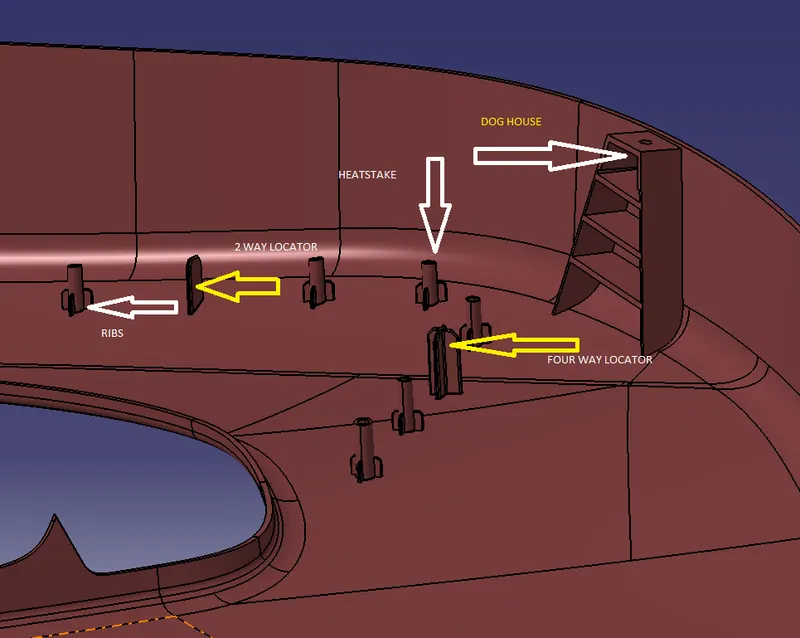
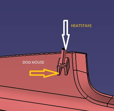
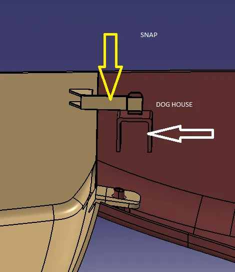
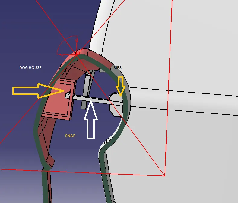
All areas are minimum Draft 0.48 deg As Shown in Below Imaje.
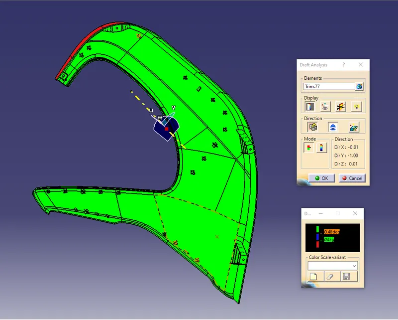
HEATSTAKES
Heat Staking is a pulsed-heat process to join two or more parts out of which one at least is made of plastic. The process is to deform the plastic material using heat and force at a set process time. The bond is made by partially de-forming the plastic part in order to fix the other.
All Dimentions Are With a Minimum Draft Angle of 0.45deg Along tooling axis
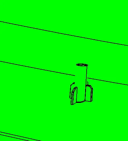
4 WAY LOCATOR
Likewise, a 4-way pin restricts 4 degrees of freedom along 2 axes. A round locating pin located concentrically in a hole is a common application of a 4-way pin, and helps to further secure the piece.
All Dimentions Are With a Minimum Draft Angle of 0.45deg Along tooling axis
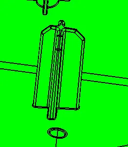
2 WAY LOCATOR
A 2-way locating pin restricts motion along 1 axis (or 2 degrees of Freedom), like a round pin in a slot.
All Dimentions Are With a Minimum Draft Angle of 0.45deg Along tooling axis
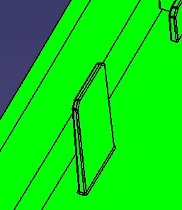
DOGHOUSE
Dog house is an engineering feature used in plastic trim design. Dog houses are used as supporting feature. Sometimes other engineering features like snaps,locators etc. are mounded on them to increase their strength.
All Dimentions Are With a Minimum Draft Angle of 0.45deg Along tooling axis
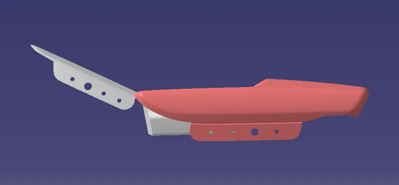
DOOR ARM REST
Arm Rest Is Divides into Two Parts Because The Can Only Be Produces With Two ToolingAxis.
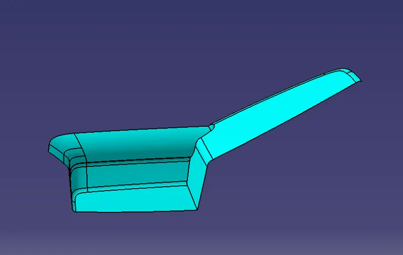
CLASS A SURFACE
PART 1
The Class A Surface is Made By Using Join Command & Joining A Number Of Components From Reference Surface.
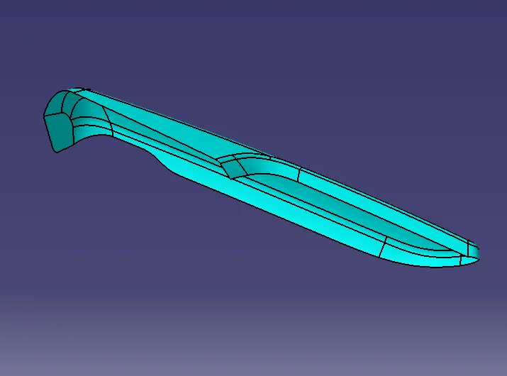
PART2
The Class A Surface is Made By Using Join Command & Joining A Number Of Components From Reference Surface.
CLASS B SURFACE
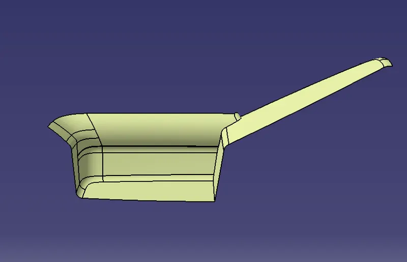
PART1
The Class B Surface Is Same As the Class A Surface But It Should Be At An Offset Of 2.5mm From The Class A Surface
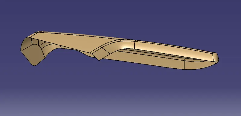
PART2
The Class B Surface Is Same As the Class A Surface But It Should Be At An Offset Of 2.5mm From The Class A Surface
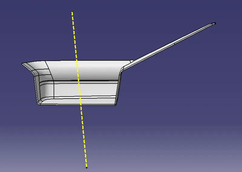
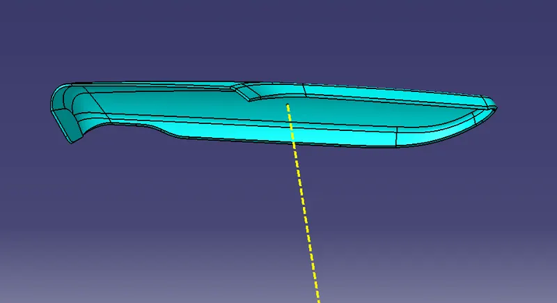
FINAL TRIM WITH TOOLING AXIS
PART 1
This Final Trim Is made From Joining Or Trimming Class A,Class B,Class C Surface Class C Surfaces are made with Reference To Class A Surface
Using Sweep and Trim Commands.
PART 2
This Final Trim Is made From Joining Or Trimming Class A,Class B,Class C Surface Class C Surfaces are made with Reference To Class A Surface
Using Sweep and Trim Commands.
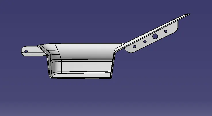
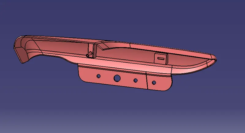
ARM REST WITH FLANGS
PART1
PART2
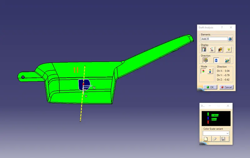
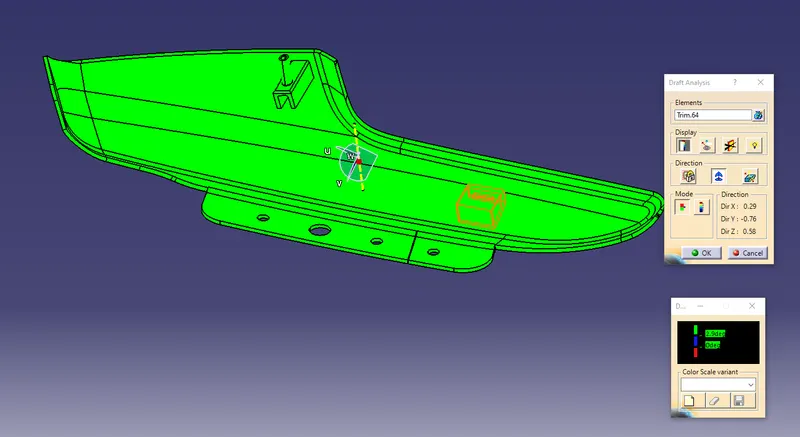
DRAFT ANALYSIS OF DOOR ARM REST
PART 1
All Areas are Minimum Draft 2.9 deg As Shown In Picture.
PART 2
All Areas are Minimum Draft 2.9 deg As Shown In Picture.
MAP POCKET
It also cxonstitute of Two Components
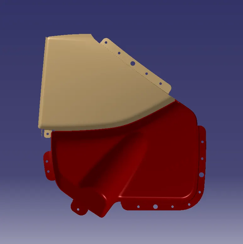
CLASS A SURFACE
COMPONENT 1
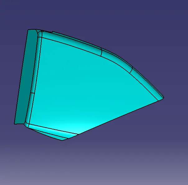
The Class A Surface is Made By Using Join Command & Joining A Number Of Components From Reference Surface.
COMPONENT 2
The Class A Surface is Made By Using Join Command & Joining A Number Of Components From Reference Surface.
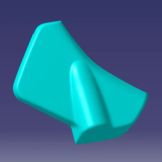
CLASS B SURFACE
COMPONENT 1
The Class B Surface Is Same As the Class A Surface But It Should Be At An Offset Of 2.5mm From The Class A Surface
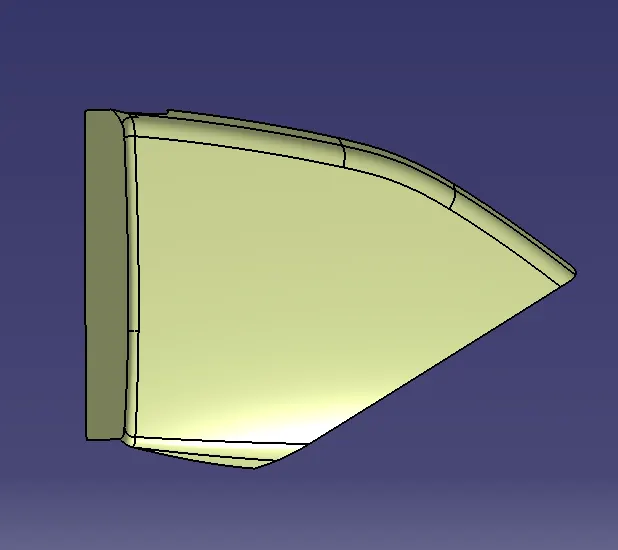
COMPONENT 2
The Class B Surface Is Same As the Class A Surface But It Should Be At An Offset Of 2.5mm From The Class A Surface
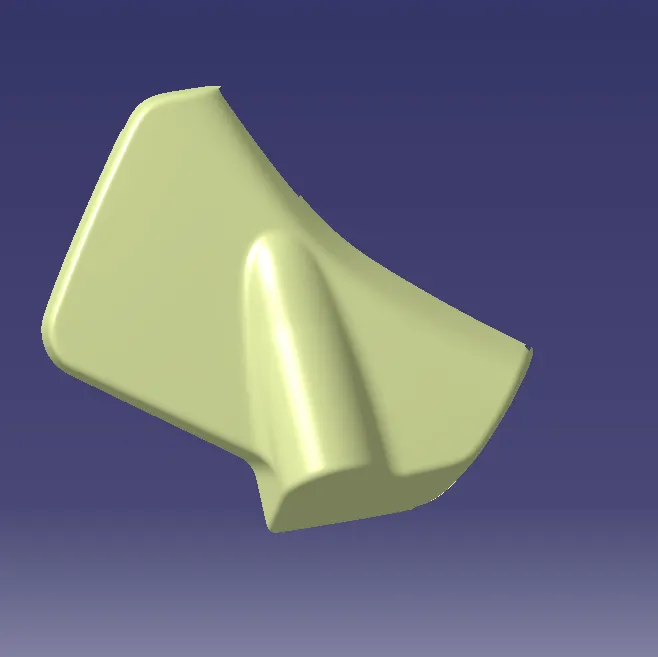
FINAL TRIM WITH TOOLIN AXIS
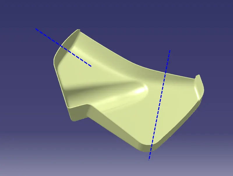
COMPONENT 1
This Final Trim Is made From Joining Or Trimming Class A,Class B,Class C Surface Class C Surfaces are made with Reference To Class A Surface
Using Sweep and Trim Commands.
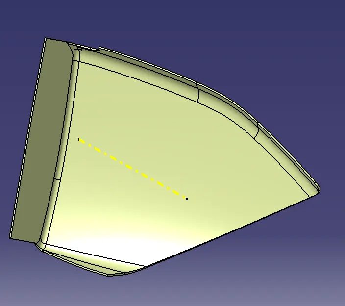
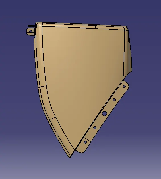
COMPONENT 2
This Final Trim Is made From Joining Or Trimming Class A,Class B,Class C Surface Class C Surfaces are made with Reference To Class A Surface
Using Sweep and Trim Commands.
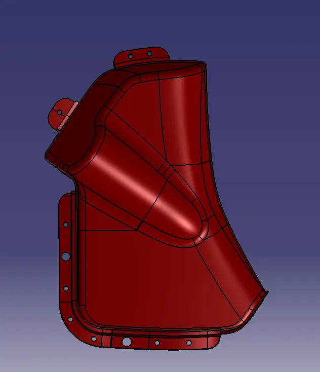
MAP POCKET WITH FLANGS
COMPONENT1
COMPONENT 2
DRAFT ANALYSIS OF MAP POCKET
COMPONENT 1
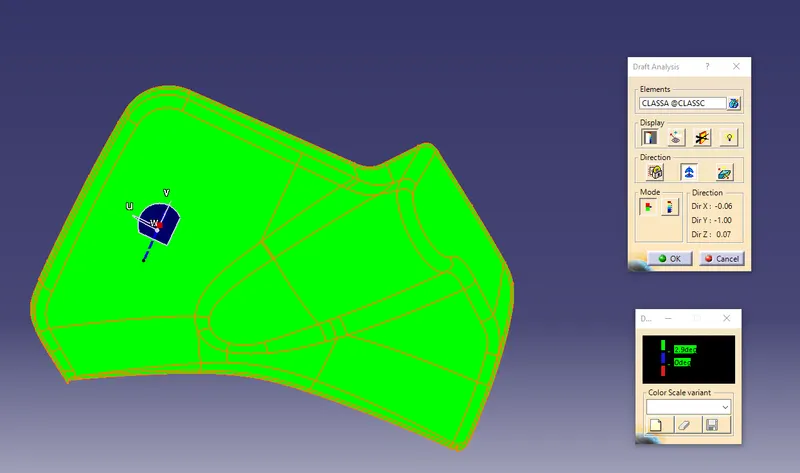
All Areas are Minimum Draft 2.9 deg As Shown In Picture.
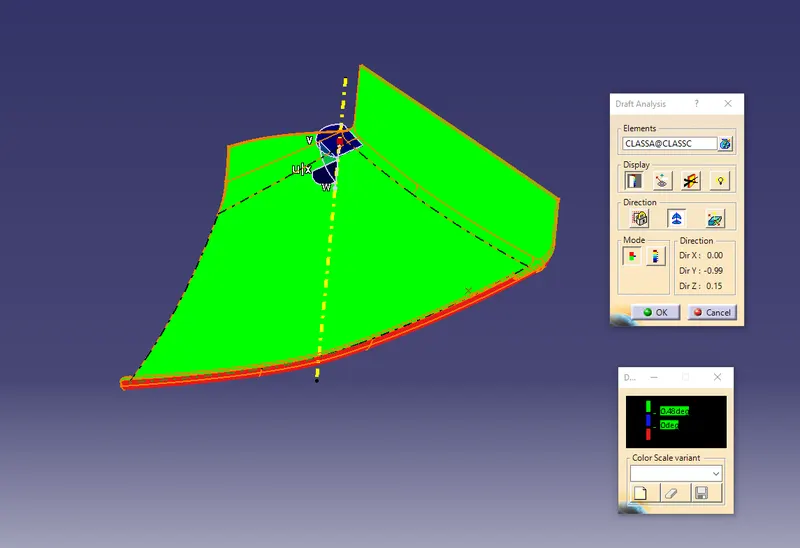
COMPONENT 2
STRIGHT TOOLING AXIS
All Areas are Minimum Draft 2.9 deg As Shown In Picture.
SIDE TOOLING AXIS