Photo Realistic Rendering
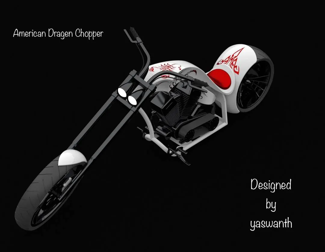
AMERICAN DRAGEN CHOPPER
Designed by konduru yaswanth
DESIGNING OF AMERICAN DRAGEN CHOPPER
AIM AND OBJECTIVE:
To skech and model every exterior part of the chopper under the part modelling environment using the solidworks.
To assembley the modelied parts in the assembley environment.
To create a photo telistic rendering of the chopper us photoview 360 and visualize.
WHAT IS SOLIDWORKS?
solidworks is a 3D solid modelling (CAD&CAE) Which id used to model a product and even do analysis on the product to check its behaviour in real world. it is developed by DASSAULT SYSTEMS.
WHAT IS PART MODELLING?
modelling in general means to create a virtual prototype of an item.it can be used for various purposes.Condide the enginer of acar. each part can be modelled separately and then be assembled together to get the engines final form.this type of modelling is called part modelling.
ABOUT FEATURE
Features are the individul shapes that,when combined,make up the part.you can also add some types of features to assembley.
Feature Toolbar
The features toolbar provides tool for creating model features.the set of features icons is very extensive so not all of them are included on the default feature toolbar.
Creating a chamfer feature
The chamfer tool creates a beveled feature on selection edges,faces,or a vertex.
Cuts
A cut is a feature that removes material from a part or an assembley.
Projected Curves
You can project a sketch curve onto a model face to create a 3D curve.You can also cerate a 3D curve that represents the intersection of two extruded surfaces generated by creating sketches on two interesting planes.
Split Lines
The Split Line tool_Split_Line_Curves.gift tool projects an entity (sketch,solid,surface,face,plane,or surface spline) to surface, or curved or plane faces.it divides a selected face into multiple spearate faces. You can split curve on multiple bodies with one command.
Create curve Through Reference Point
Create a curve through points located one or more planes.
Composite curve
From a combination of curves, sketch geometry,and model edges.
Deforms
Use the deform feature to alter shapes of complex surface or solid models,either in a locsl area or globally,without concern for the sketches or feature constrains used to create the models.
Dome
Select one or more planar or non-planar faces,You can apply domes to faces whose centroid lies outside the face.This allows you to apply domes to irregularly shapes contours.
Elliptical dome
Specify an elliptical dome for cylindrical or conical models.An elliptical dome's shape is a half ellipsoid,With a height equal to one of the ellipsoid radii.
Extrudes
The Extrude propertyManager defines the characteristics of extruded features. You can also use instant3D and Rapidsketch to create extrudes
Fillets
Fillet/Round creates a rounded internal or external face on the part. You can fillet all edges of a face, selected sets of faces,selected edges,or edge loops.
Library Features
A library features is a frequently used feature, or combination of features, that you ceate once and then and then save in a library for future use. Most feature types are supported,some With certain limitation.
Lofts
Loft creates a feature by making transition between profiles.A loft can be a base,boss,cut,orsurface.
Patterns and mirroring
Pattern repeats the selection feature in an array based on a seed feature.You can crate a linear pattern,a circular pattern,a curve driven pattern,a fill pattern,
or use sketch points or table coordination to create a pattern.
Revolves
Revolves add or remove material by revolving one or more profiles around a centerline.You can create revolved boss/based,revolved cuts, or revolved surfaces. The revolve feture can be a solid,a thin feature,or a surface.
Shells
The sheel tool hollows out a part,leaves open the faces you select, and creates thin-Walled features on the remaining faces.
Surface
Surfaces are a type of geometry that can br used to create solid features.surface tool are avilable on the surfaces toolbar.
Sweeps
Sweep creates a based,boss,cut,or surfaces by moving a profile(section) along a path. A sweep can be simple or complex.
Appearance
To adjust the transparency level of an appearance,set Transparent Amount on the illumination tab.
offset
The adjust command is used to create a similar sketch in some distance as required.
Trim
The trim command can be used to remove the extra portions in the sketch the trim command basically works based on the some reference point,edge etc.
Dynamic mirror
This tool allows the used to mirror a sketch about a line while the user us creating their sketch. Depending on the design intent this tool can save an immense amount of time.
Shell
The shell command is used to create a thickened surface either it can be done in the interior or exterior surface.
Chamfer
The chamfer command creates a beveled feature on the selection edge,face and vertex etc.
Linear Pattern
The linear pattern is used to create a similar model either in linear XYZ directions. The pattern is created based on the reference edge,face etc.
Circular Pattern
The circular pattern is used to create a similar solid surface in a circular direction upto user defined instances.
PARTS TO BE MODELLED IN CHOPPER
TRANSMISSION BELT
KICK STAND
FRONT FENDER
RARE FENDER
OIL TANK
CHAIN
PEDAL
FRONT WHEEL
RARE WHEEL
FRONT FORK
CHASSIS
ENGINE
GAS TANK
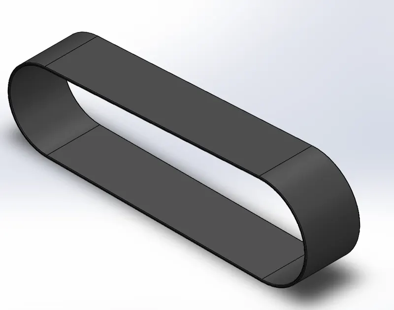
TRANSMISSION BELT
Commands used-2D sketch,lines,circle,trim,offset,boss/base,smart dimensions,fillets.
USES:
Belts are mechanical elements used for power transmission without phase shift.
KICKSTAND
Commands used-2D sketch,Ellipse,smart dimention,spline,reference
geometry,pierse relation,loftedboss/base feature,elliptical dome, centre rectangle,extrude,circle,fillets.
USES:
A kickstand is a device on a motorcycle that allows the bike to be kept upright without leaning
against another object or the aid of a person.
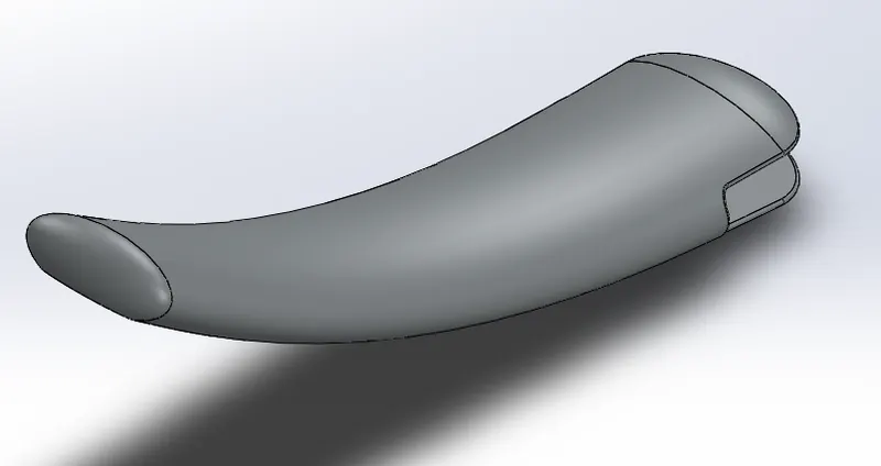
FRONT FENDER
Commands Used-2D sketch,3point arc,offset,extent entities,line,powertrim,smart dimentions,dynamic mirror,spline,extrudecut,split,fillets.
USES:
Its primary purpose is to prevent sand, mud, rocks, liquids, and other road spray from being
thrown into the air by the rotating tire.
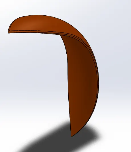
RARE FENDER
Commands Used-2D sketch,3point arc,offset,extend entities,line,powertrim,smart dimentions,dynamic mirror<spline,extrudecut,split,fillets.
USES:
Its primary purpose is to prevent sand, mud, rocks, liquids, and other road spray from being
thrown into the air by the rotating tire.
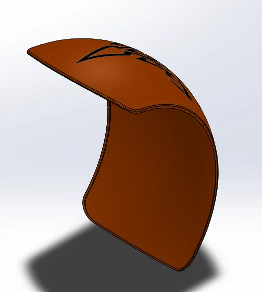
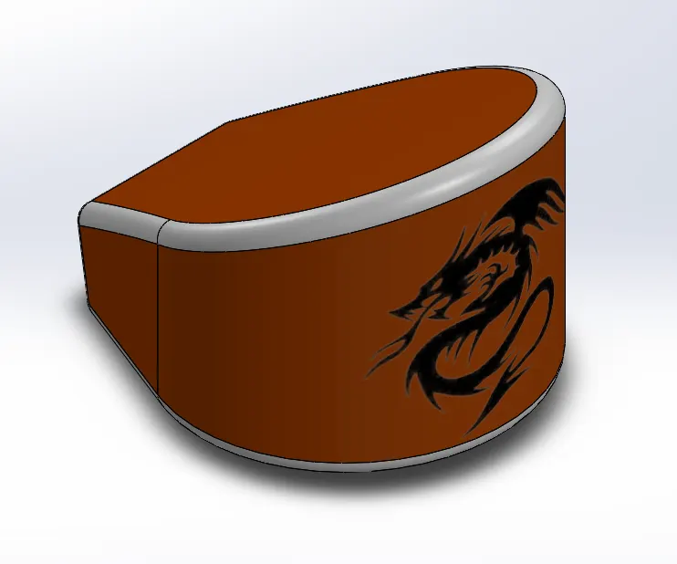
OIL TANK
Commands Used-2D sketch,line,sketch point,Dynamic Mirrror
Enttitles,Extrude,spline,Combine Feature,Fillets,Shell,appearance.
USES:
the system must contain a given quantity of fuel and must avoid leakage and limit evaporative emissions.
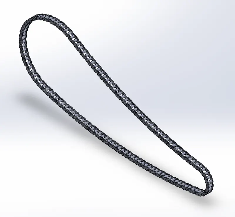
CHAIN
Commands Used-2D Sketch,line,Smart Dimention,Circle,3-point arc,powerTrim,Make Block,Extrude,Bose/Base,fillets,curve Driven Pattern,InsertBlock,Convert Entities<Slot,Mirror,Appearance.
USES:
A Motorcycle chain is a roller chain that transfers power from the spracket to the drive-wheel of a Motorcycle thus propelling it.
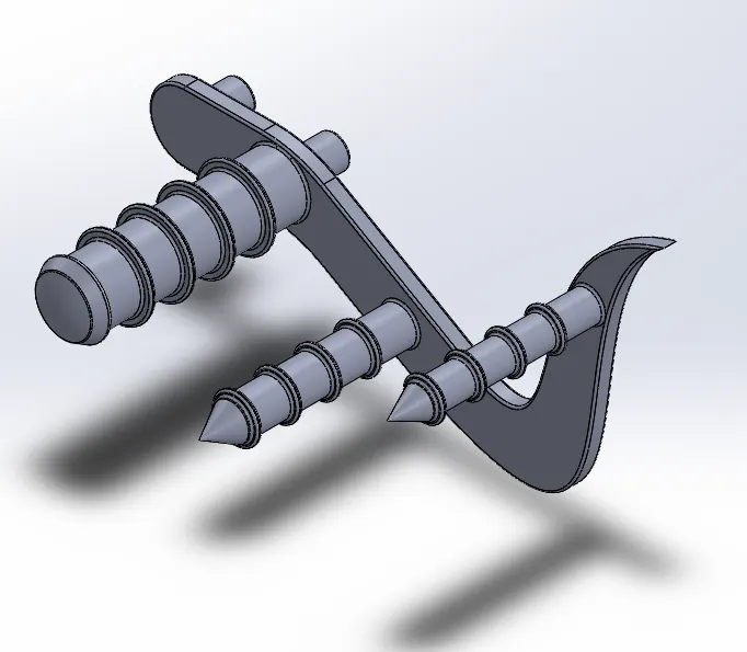
PEDAL
Commands Used-2D Sketch,Construction Line,Smart Dimentions,Line,3-p=Point arc,Spline
USES:
The pedal is the part of a Motorcycle that the rider pushes with their foot to propel the vehicle.
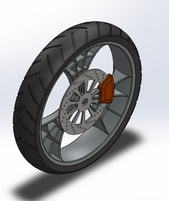
FRONT WHEEL
Commands Used-2D Sketch,Line,Smart Dimentions,3-Point Arc,Sketch Fillet,Revolved Boss/Boasww,Spline,Mirror,Excluded Boss/Base,OffsetEntities,Extrude Cut,Intersection Entities,Revolved Cut,Circular Feature,Combine,Fillets,Linar Pattern,Circular pattern,Appearance.
USES:
Front-Wheel Drive. Front-wheel drive reduces weight, decreases production costs, and improves fuel economy compared to a rear-wheel-drive system.
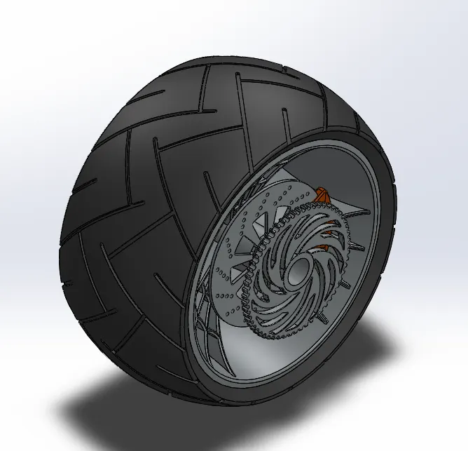
RARE WHEEL
Commands Used-2D Sketch,revolve Boss/Base,Reference Geometry New Plane,Fillet,Extrude Boss/Base,Smart Dimentions,Spline,MIrror.Circular Pattern,Revolve Cut,Linear Pattern,Chamfer,Appearance.
USES:
During dry conditions, rear-wheel drive improves handling due to “load transfer” in acceleration and more even weight distribution.
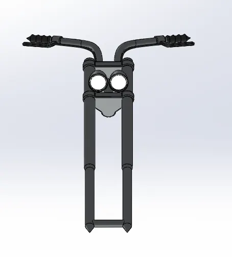
FRONT FORK
Commands USed 2-D Sketch,Revolved Boss/Base,REference Geometry Plane,Extrude Boss/Base,Plan,Fillet,Linear Pattern,Smart Dimension,Sheel,Dome,Projected,Swept Boss/Base,Reference Geometry Axis,Sweep Boss/Base,Mirror,Appearance.
USES:
Most motorcycles today use telescopic forks for the front suspension.
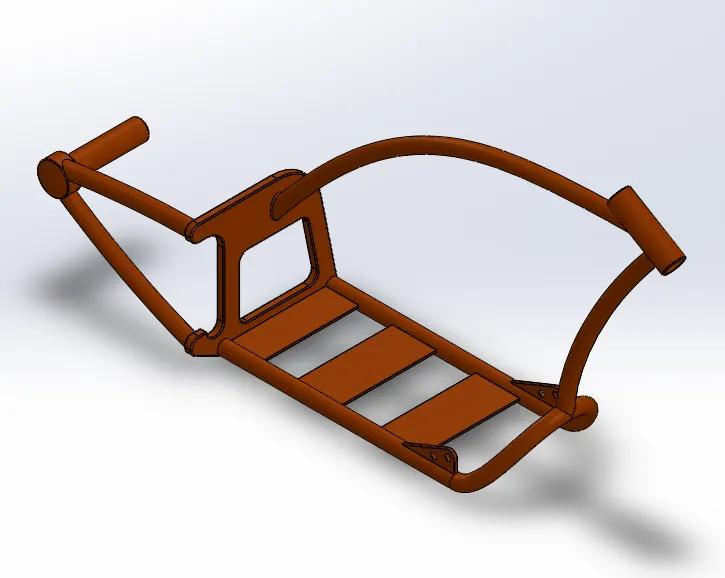
CHASSIS
Commands Used-2D Sketch Picture, Projected
USES:
Supports or bears the load of the vehicle body.
Supports a load of passengers as well as the luggage.
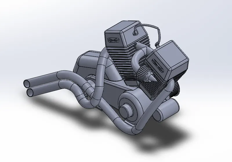
ENGINE
Commands Used 2-D Sketch,Sketch Picture,Extrude Boss/Base, New Reference Geometry Plane,Revolve Boss/Base,Circular Pattern, Extrude Cut,Dome,Chamfer,Fillet,Linear Pattern,Mirror,Circular Pattern,Swept Boss/Base,Projected Curve.
USES:
An engine or motor is a machine designed to convert one form of energy into mechanical energy.
GAS TANK
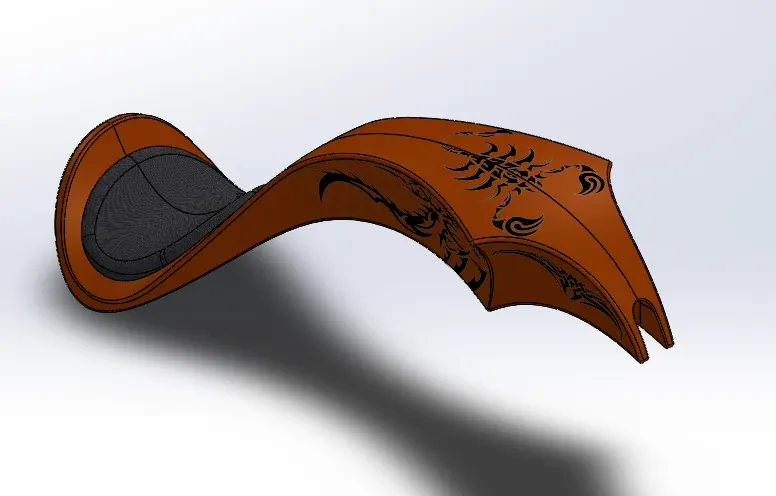
Commands Used 2-D Sketch,Sketch Picture,Referrence Geometry Plane,Spline,Split Line,Projected Curve,Loft,Smart Dimentions,Mirror,Offset,Knit Surface,Shell Feature,Extrude Cut,Move Tool,Appearance.
USES:
the main function of the Gas tank is simply to hold Gas.
ASSEMBLEY OF CHOPPER
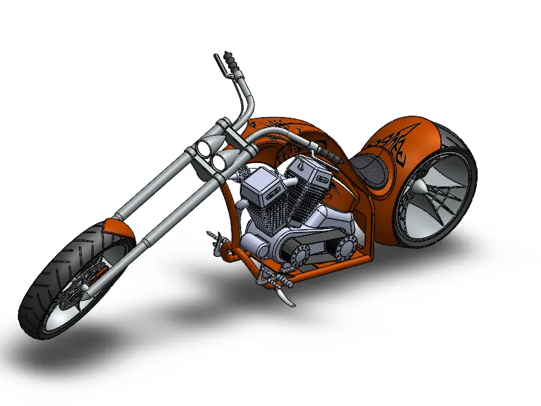
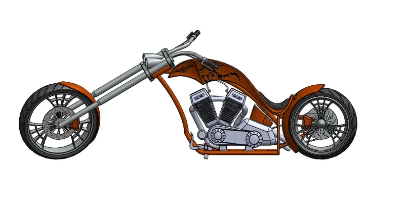
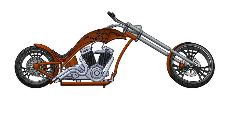
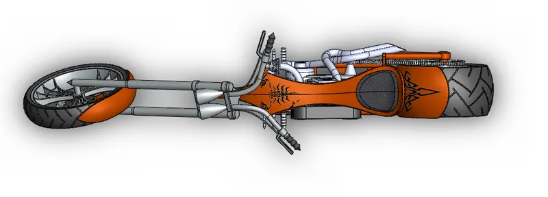
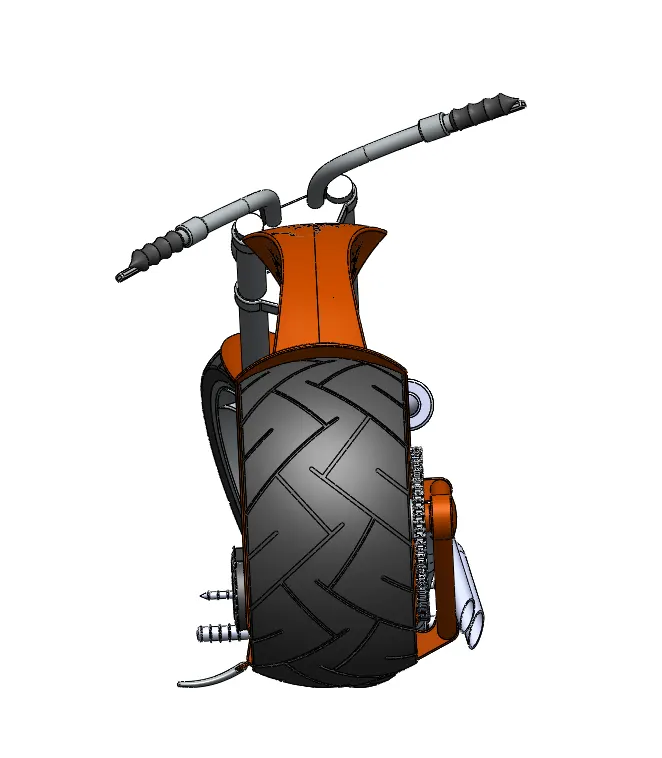
The Chopper Assembley is dobe in the assembley environment all the parts Which are modelled before are inserted into the assembly environment by using insert component feature. The components are fixed in assembley environment based on some references such as Planed,Mates etc.
ISOMETRIC VIEW
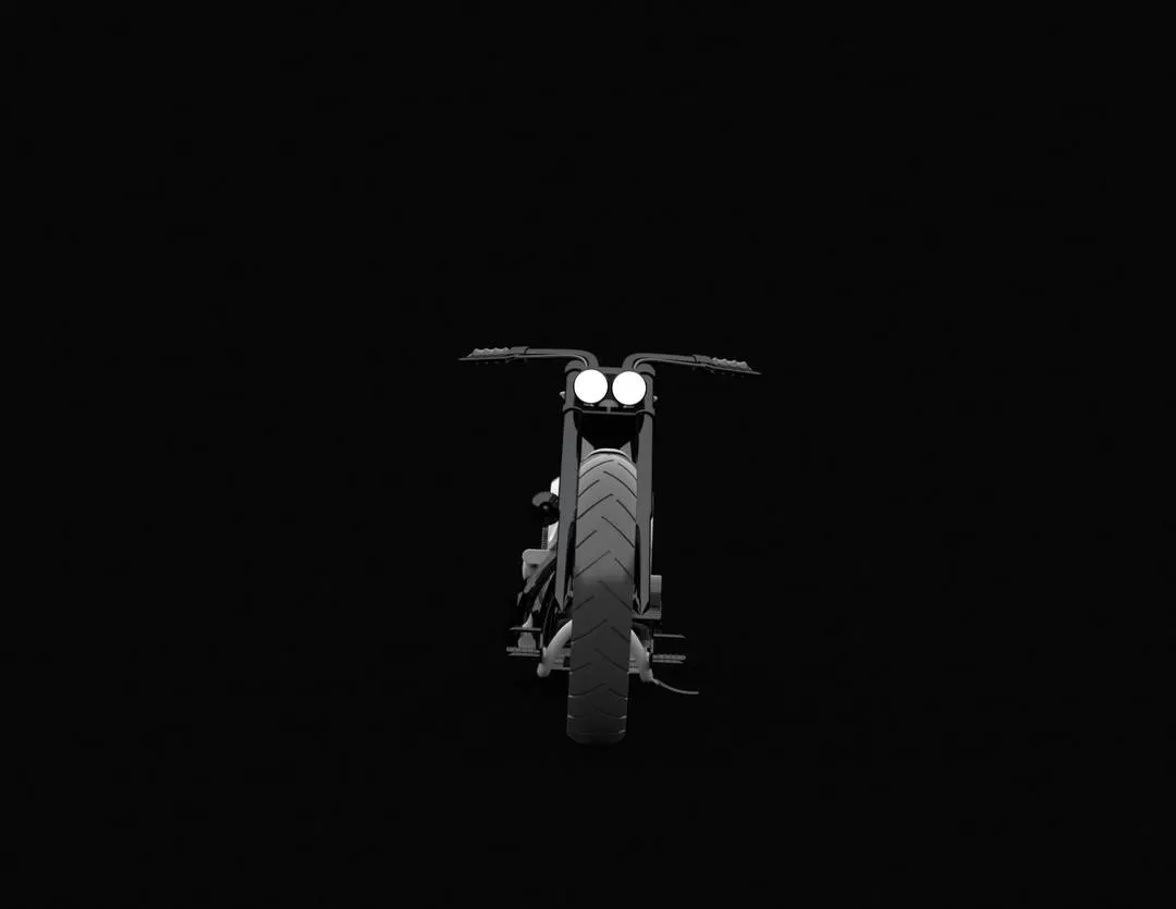
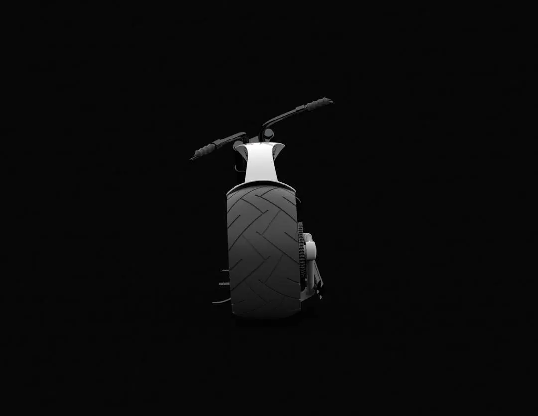
FRONT VIEW
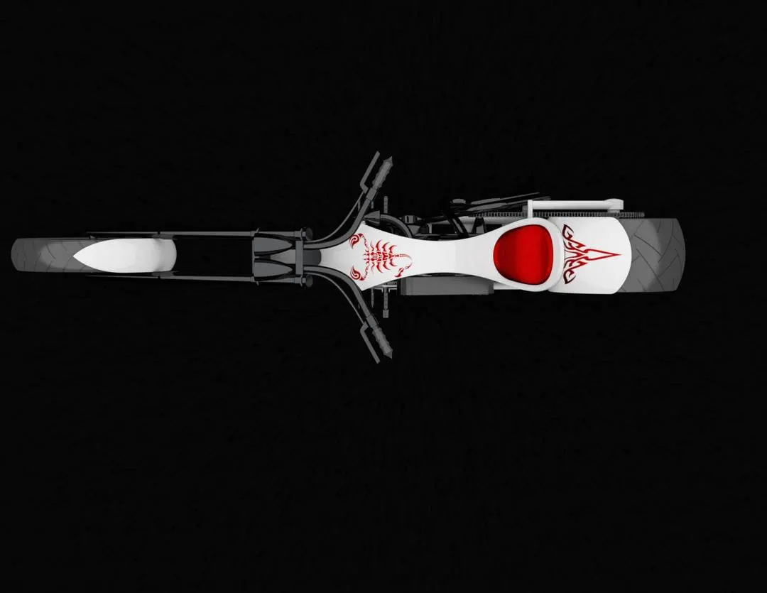
TOP VIEW
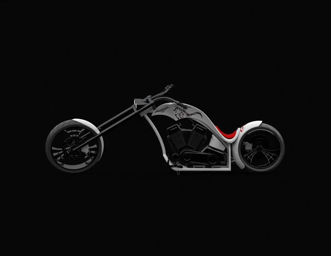
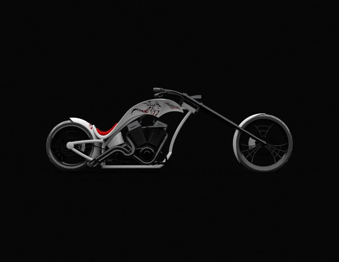
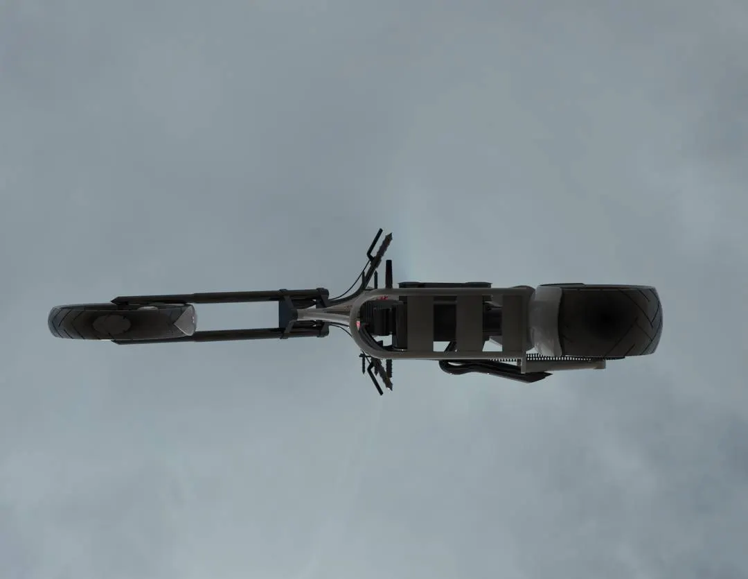
RIGHT VIEW
MATES
Mates are used to create a relationship among the parts being insertes into the assembley based on the fixed part,With respect to the fixed part all the parts can be mated.
As you define the mates, You define the allowable direction of linear and rotational motion of the part in the environment
ASSEMBLY
Commands Used- insert Components,Mate,Mirror Components.
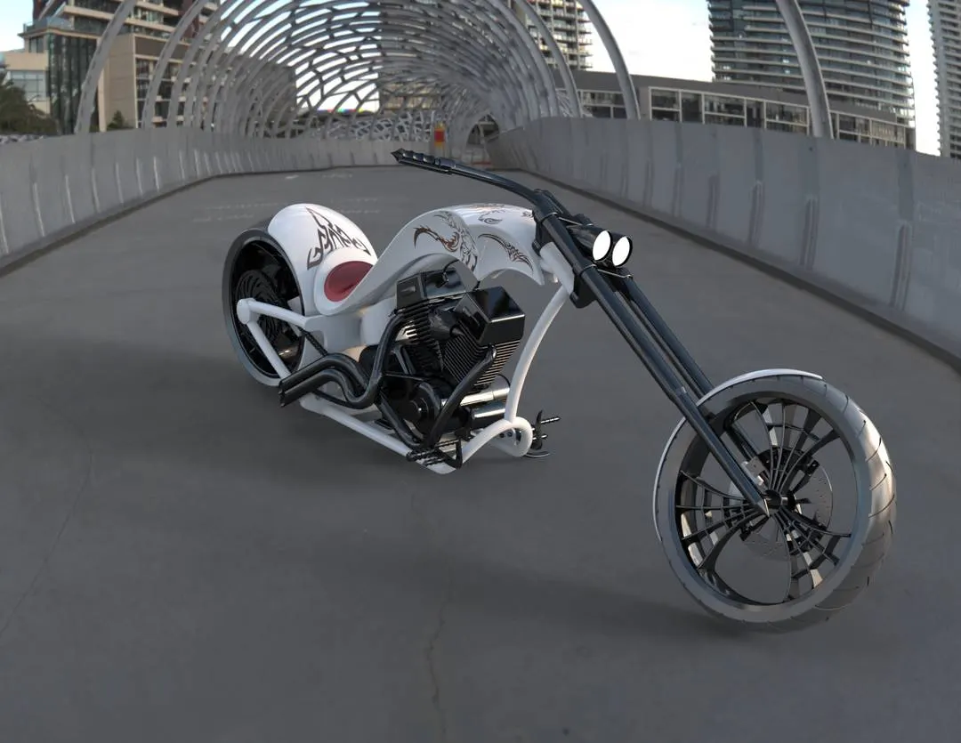
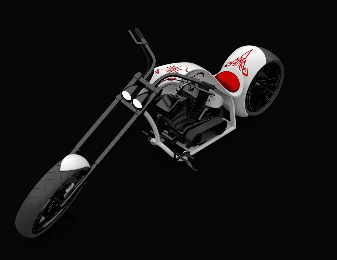
PHOTOREALISTIC RENDERING OF AMERICAN DRAGEN CHOPPER
REALISTIC RENDERED PICTURE
REALISTIC RENDERING PARTS
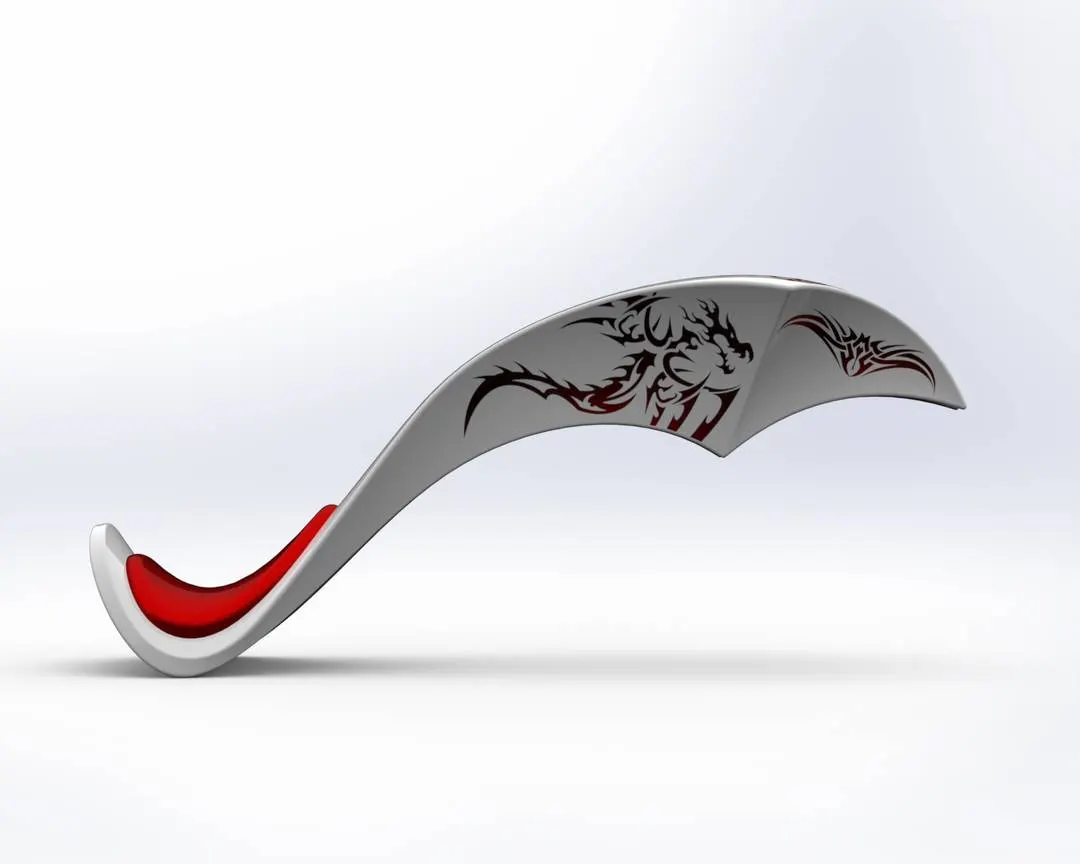
GAS TANK
OIL TANK
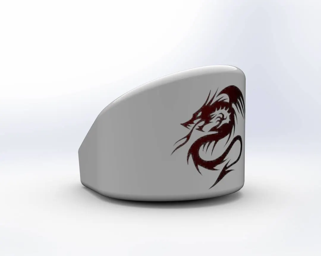
RARE FENDER:
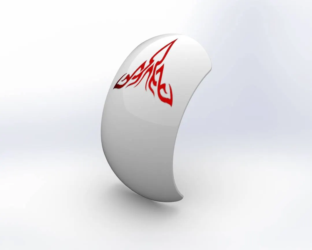
Rendering is the process of converting a 3D model into a realistic imajes.
In solidworks the redering process can be done using solidworks add-in such a photoview 360.
in photo view 360 is enabled it Will enable the render tool,inside the render tools used can edit the appearance and decals.
In solidworks visualize also changed appearance,decals,camera view etc.
By using the final render option one can predict hoe realistic the 3D model may look.
Changing the DRAGEN CHOPPER color in solidworks visualize.
CONCLUSION
All the parts of the AMERICAN DRAGEN CHOPPER are modelled and assembled together successfully using solidworks and the assembley chopper is rendered using the photoview 360 and Visualize.