Car door arm rest
Development of a Door Trim panel
Aim:
- To create a CAD model (Door Trim Panel) with attachment features considering the given inputs, design rules, and following the OEM standards.
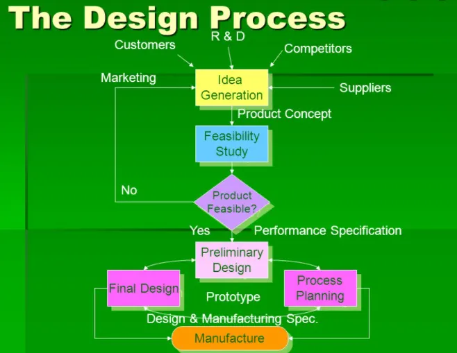
- This Project explains, in brief, the Design life cycle followed in the automotive industry by working on Practical Model car interior door trim which is a Car interior trim Part. In this report, we have explained the steps followed to create a solid body of the pillar Cover taking Class A Surface as Input and Creating a Tooling axis and B surface with respect to the Class A Surface and Creation of Class C Surface and also the Draft Analysis. The attachment features are also designed and reported as per the given master section considering all the design rules for the creation of ribs and doghouse.
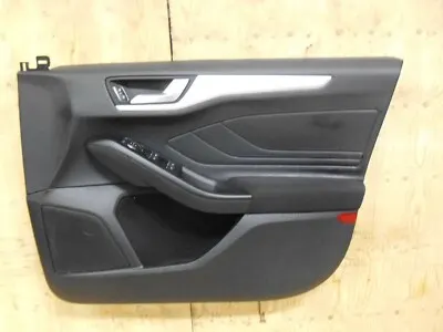
Side Door Plastic Trim :
An interior plastic component is attached to the inner side of the door. This product improves the appearance of the vehicle interior and also creates a more comfortable interior by providing a variety of fitments and functions.
OVERVIEW OF DESIGN CYCLE :
METHODOLOGY:
Creating the Tooling Axis:
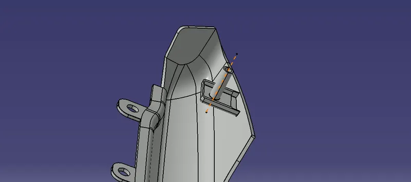
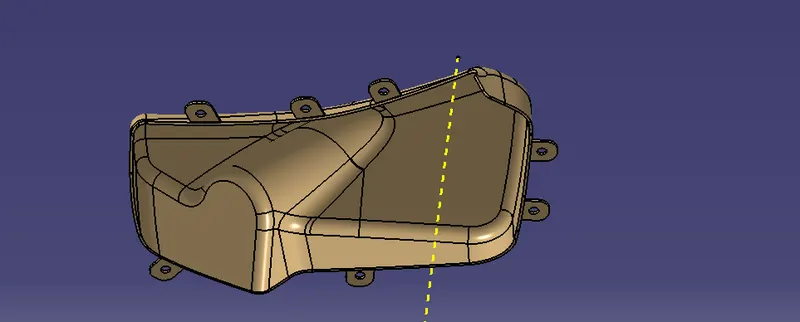
The tooling direction is used to find the direction in which the part is removed from the core and cavity. The draft angle should be positive to the tooling axis to manufacture the component easily. The step-by-step procedure of creating the tooling axis is given below.
TOOLING AXIS FOR ARMREST ARM SECTION
TOOLING AXIS FOR MAP POCKET
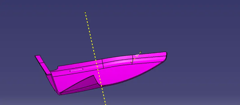
TOOLING AXIS FOR SPEAKER BEZEL
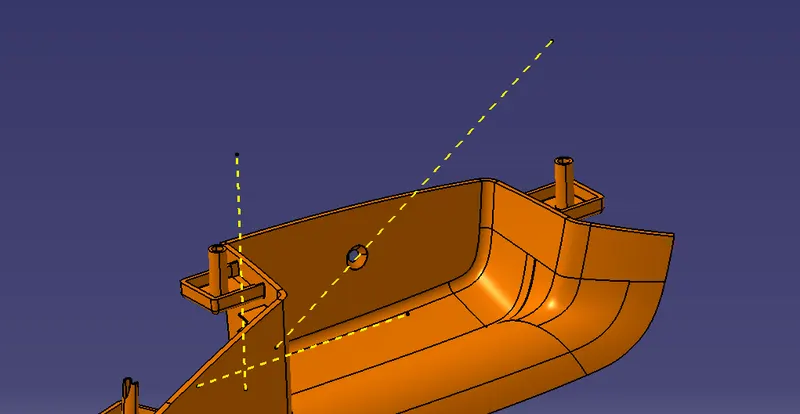
TOOLING AXIS FOR SWITCH BEZEL
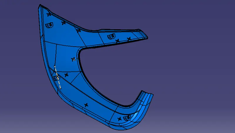
TOOLING AXIS FOR LOWER SUBSTRATE
DRAFT ANALYSIS:
The first step before starting the model should always be to check if the surface has enough draft that it will not create any problems while ejecting from the mold. This seems like a big task as we have to foresee something that will come at a very later stage. But this is done by a small process called draft analysis. This analysis tells us whether our component will be safely ejected in the tooling axis we have provided. Some components require a side core where they are undercuts, holes, or projections on the sidewalls, so for this, we need a different tooling axis and a different analysis is required to check those areas. Draft analysis shows color codes that are defined by the user for different values which also are defined by the user. These colors help us to analyze if the component is clearing the draft analysis and we are good to go ahead or not. In case the component fails the analysis for Class A then we have to submit the draft analysis report to the higher authority so that surface of the component can be improved. The failing analysis simply means that the component does not have the required draft value it must have. In case our solid model which we develop fails the analysis at some parts then we have to correct it ourselves.
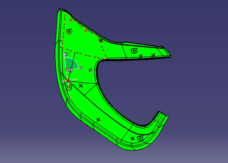
DRAFT ANALYSIS FOR LOWER SUBSTRATE
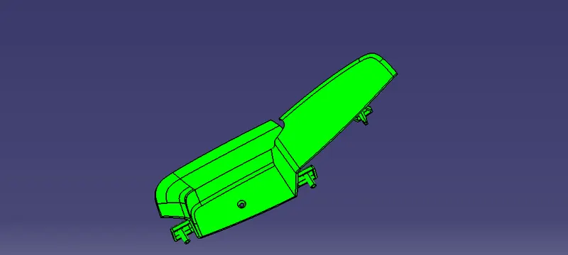
DRFAT ANALYSIS FOR SWITCH BEZEL
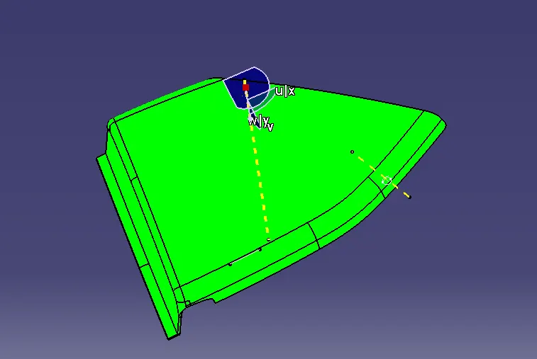
DRAFT ANALYSIS FOR SPEAKER BEZEL
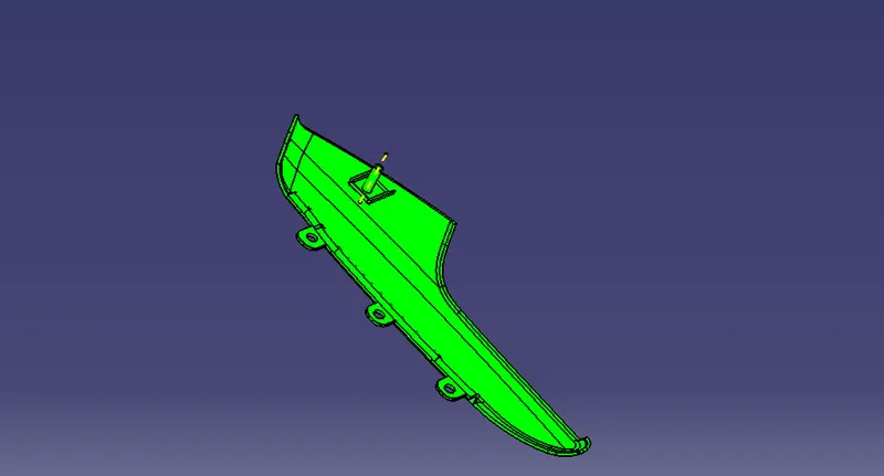
DRAFT ANALYSIS FOR ARM SECTION
CLASS B SURFACE:
To create the CLASS-B surface, the CLASS-A surface is offset by 2.5mm (since the thickness of the component is 2.5mm). From the master sections which is given to us as input, we can measure the thickness of the component.
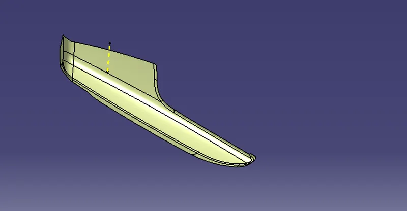
B SURFACE FOR ARK SECTION
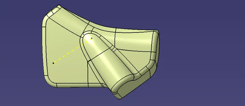
B - SURFACE FOR MAP POCKET
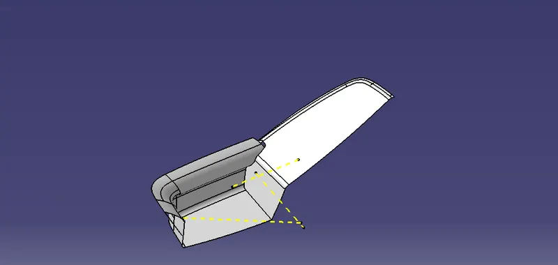
B - SURFACE FOR SWITCH BEZEL
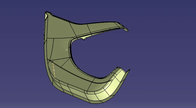
B - SURFACE FOR LOWER SUBSTRATE
CLASS-C SURFACE:
- To create a CLASS C surface first extract the boundaries of the CLASS A surface.
- After extracting the boundary, we need to perform a smooth (max. Deviation as 0.001mm) operation on it to create a continuous tangent surface.
- Now using the ‘sweep’ option create the C surface by sweeping the boundary of the CLASS-A surface at an angle of 3deg outwards to the tooling direction.
- And then trim it from the class a to get the thicked lower substrate.
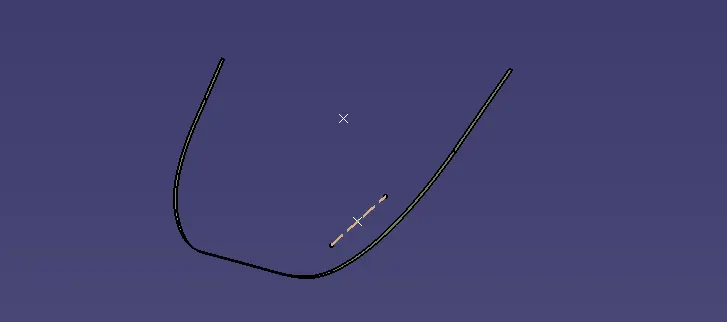
C -SURFACE FOR LOWER SUBSTRATE
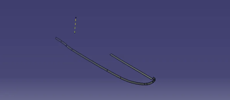
C - SURFACE FOR ARM SECTION
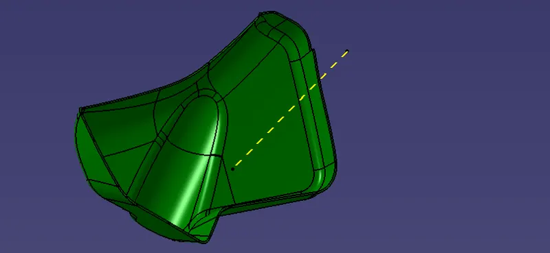
C - SURFACE FOR MAP POCKET
CLOSED SURFACE :
- Since these surfaces are hollow, we need to close them to form a thick solid component.
- Using the “CLOSE SURFACE” option in PART WORKBENCH, a solid body from the closed surface can be formed.
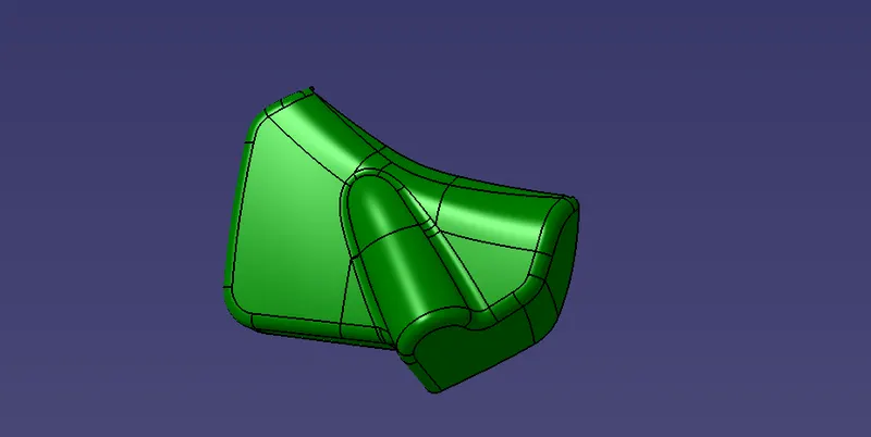
CLOSED SURFACE FOR MAP POCKET
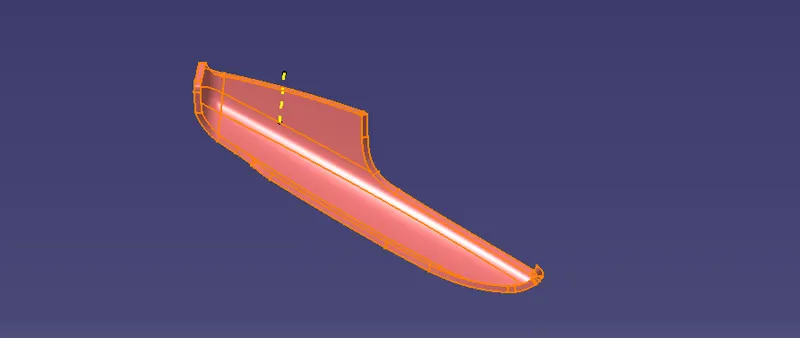
CLOSED SURFACE FOR ARM SECTION
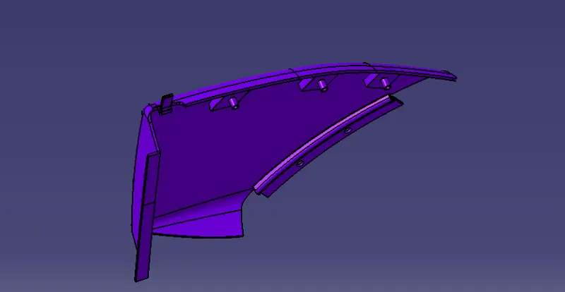
CLOSED SURFACE FOR SIDE SPEAKER BEZEL
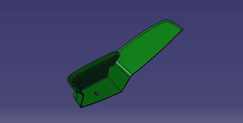
CLOSED SURFACE FOR SWITCH BEZEL
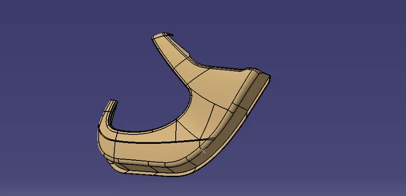
CLOSED SURFACE FOR LOWER SUBSTRATE
DOG HOUSE:
- The Dog House is an engineering feature that is used in the plastic trim design. It is used as a supporting feature for other engineering features like snaps, locators, push pins, etc. that are mounted on the Dog house to increase their strength and also to avoid the sink marks.
- To create the Dog House, we first need to create a sketch that is rectangular with one side is open and then extruding it.
- Now using thicken option in PART WORKBENCH, give it a thickness of 2mm to form a solid.
- To get the inner shape of the Dog House the following Design Rules are followed.
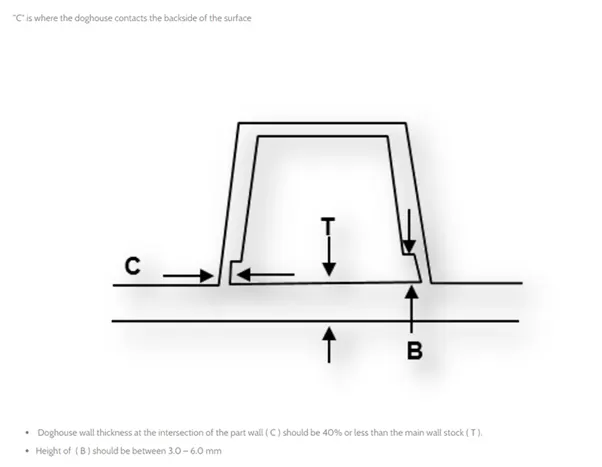
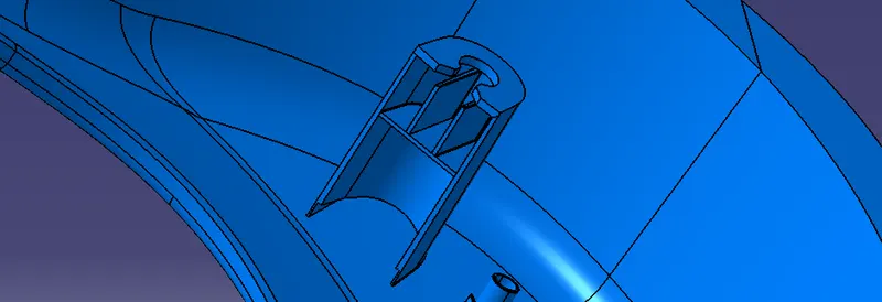
DOG HOUSE IN LOWER SUBSTATE
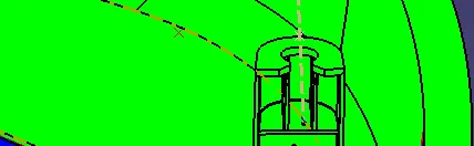
DRAFT ANALYSIS FOR DOG HOUSE
PUSH PINS:
- Push Pins are used for joining one component to another and are attached to the Dog House.
- To create a Push Pin a sketch is drawn following the below details.
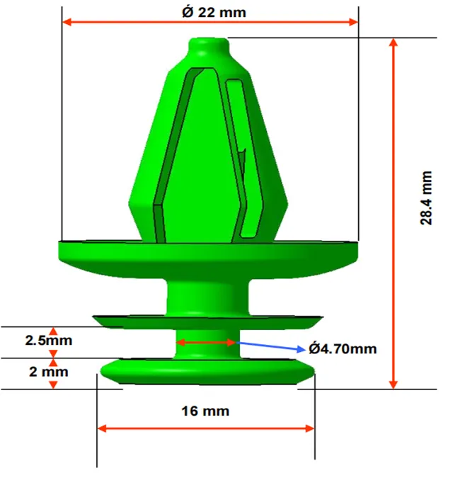
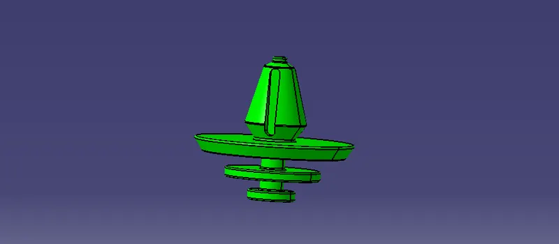
PUSHPINS
HEAT STAKES & LOCATORS :
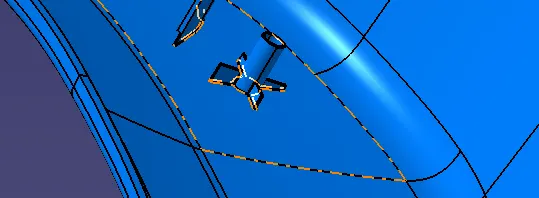
- Heat stakes are used to join two or more parts that are made of plastic with the help of the heat staking process. The heat staking process involves the deformation of the plastic material using heat and force to fix it with the other parts.
- To create the Heat Stake, we need to create a sketch with a circle of diameter 8mm. Now extrude this sketch to a height such that it is passing through the Flange. Using the shell option, thicken this extrude (thickness 2mm) to form a solid and give it a draft of 0.5 deg. these heat stakes are designed as per the design rule
FINAL ASSEMBLY PRODUCT PROCEDURE :
- 1)First create all the parts of the MASTER SECTION DEVELOPMENT SEPERATED MODEL.
- 2)Create all the parts separately in the part workbench or generative workbench.
- 3)First create the sketch of the part in the sketching workbench and make sure that the sketch is Iso constraint.
- 4)Then pad that sketch using pad feature in the part workbench or extrude and trim accordingly in generative workbench.
- 5)Use Boolean operations and add or remove to obtain the required output.
- 6)While creating the parts in the generative workbench make sure that you close the surface of the part you created.
- 7)Create all the parts and save the CAT. Part of all the parts that you have created separately.
- 8)Then go to the assembly workbench and open all the parts that you created using the “open existing component” feature.
- 9)Then assemble them accordingly using the constraint toolbox and move the parts in various directions as you need using the move toolbar.
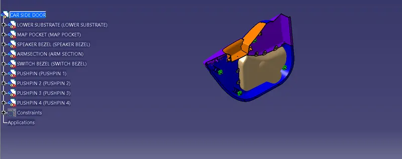
FINAL ASSEMBLY
CONCLUSION :
- A Door Trim Panel with engineering features using the master section and surface as an input has been successfully created and draft analysis has also been performed for the same.
- The specified class A surface is used as the input for the creation of the car interior door trim, and Class B and C surfaces are developed with the help of the Class A surface. The design guidelines are used to produce the specified master section attachment features, such as heat stakes, flanges, dog house, and push clips. The draught analysis was carried out to examine the component's draught in order to manufacture it more readily by applying 3 degrees and 0.5-degree draught to the surface of the attachment characteristics. With all of the data and the report, we can infer that draught analysis is critical when designing any plastic component so that the plastic can be molded readily. The analysis will determine whether all surfaces are suitable for pulling.