Week 11 - Final project
Final Report
Creation of product file from the given Class A data with all the parts separated out.
Solid Body Creation
The first step was to create the part bodies of all the 4 components, Arm Rest, Lower Substrate, Upper Map Pocket and Lower Map Pocket. From the given Class A surfaces I managed to create the Class B surface and also the Class C Surface. The offset for the Class B Surface of all components was 2.5mm and with the sweep function I created the Class C Surface from the Class A and joined them both together. The final trim was then made with the Class B and the joined A& B. And hence we got the product with closed surface of all the components with a nominal thickness of 2.5mm.
Flange Creation
By referring the master section provided in the class A the first flange was created and then the other flanges was created by extraction the boundary of class A and using it as the guide curve and the extracted master section as the profile. Some of the flanges in Lower map pocket was created with translation tool. The Flanges of all the 4 components were given a draft of 0.5 degrees for easy removal of component after Injection molding. The thickness of the Flange is same as that of the nominal thickness of the solid bodies that we created which is 2.5mm. After the draft a particular fillet radius of 3mm was given at the end corners of the flange and 0.5mm fillet around the edges of the flange.
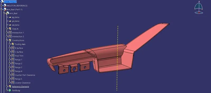
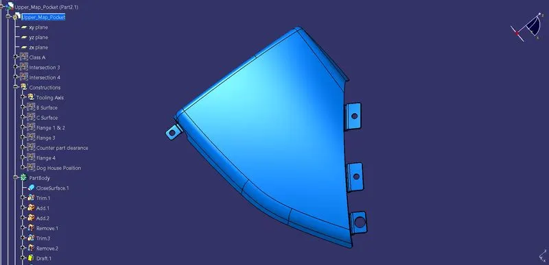
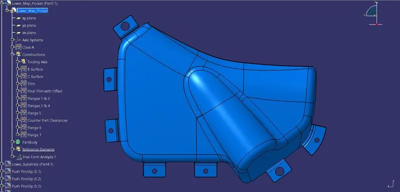
A total of 5 Flanges was created on the armrest where 4 of them was for the heat stakes and one was for the 4 way locator. 4 Flanges was created on the upper map pocket where 3 of them was for heat stakes and the other was for the 4 way locator. And finally a total of 7 flanges was created on the lower map pocket where 2 of them was for the 4 way locator and the rest of them for heat stakes.
Heat Stakes and its Ribs
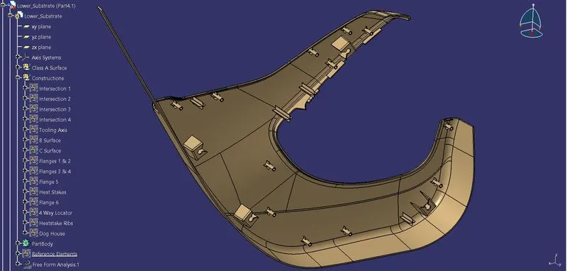
Heat stakes are for part to part attachment. Heat stakes are the components created on the lower substrate in order to attach it with all other solid bodies. A total of 12 heat stakes are made on the lower substrate with dimensions of 7.5mm and 4.5mm as the outer and inner diameters respectively. A draft of 0.5 degree is given on the outer surface of the heat stakes and edge fillet radius of 0.5mm was given to it. 4 heat stakes was made to attach the lower substrate with the Arm Rest. Another 3 heat stakes was made to attach the lower substrate with the Upper Map pocket and the rest of the heat stakes was used to attach the lower map pocket and the lower substrate.
An approximate height of 8mm was maintained between the top part of the flange and the top part of the heat stakes. Pockets were created on the flange to accommodate the heat stakes with a clearance of 0.5mm all around. A minimum distance of 60-80mm was maintained between the heat stakes.
4 Ribs around each heat stakes were made to support the heat stakes from breaking at any point when a tight force is applied. The thickness was 1mm neutral with a draft of 0.5 degrees all around. And a minimum fillet radius and chamfer was provided on all the heat stake ribs.
The principle we use here is the 3-2-1 principle.
4 Way Locators
Four 4 way locators are created on the lower substrate for each of the sold bodies. And their height was made higher than the heat stakes. The locators were given a draft of 0.5 degrees and a nominal fillet radius and chamfer at the 4 corners. The draft was given with the pulling directions of tooling axis of the respective solid bodies.
Dog House and Push pins/Clips
A total of 4 dog houses was created in the lower substrate for the accommodation of pushpins on top of it. The main purpose of pushpin with the dog house is the Door Panel Attachment. The dog house wall thickness at the intersection of part wall is given at 40% of main wall thickness which is 1mm in this case.
Proper draft angle is provided on the inner and outer walls of the Dog House to clear the tooling axis and an additional Side Core tooling Axis is created to clear the inner sides of the Dog house while manufacturing and draft angle is provided with respect to that. A fillet radius of 2.5mm is provides on the outside edges and the overall thickness before the draft was 2mm. The draft analysis was given on the dog house using the side core tooling axis.
A particular pocket cutout was made on top of the dog house to accommodate proper seating of the pushpins.
Assembly
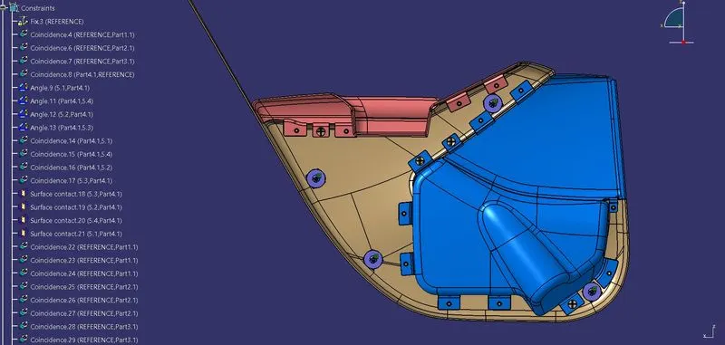
A Skeleton Reference was created to constraint all the parts and to assemble the push pins onto the dog house.
ARM REST
UPPER MAP POCKET
LOWER MAP POCKET
LOWER SUBSTRATE
FINAL PRODUCT WITH CONSTRAINTS