Week 8 - Challenge 1 - Draft Analysis on a Fan Cover
Screenshots of the Draft Analysis Report
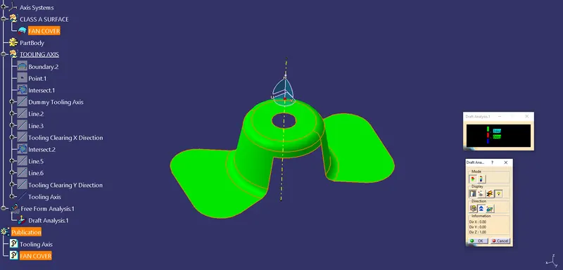
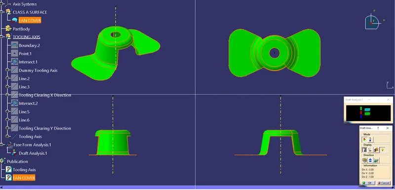
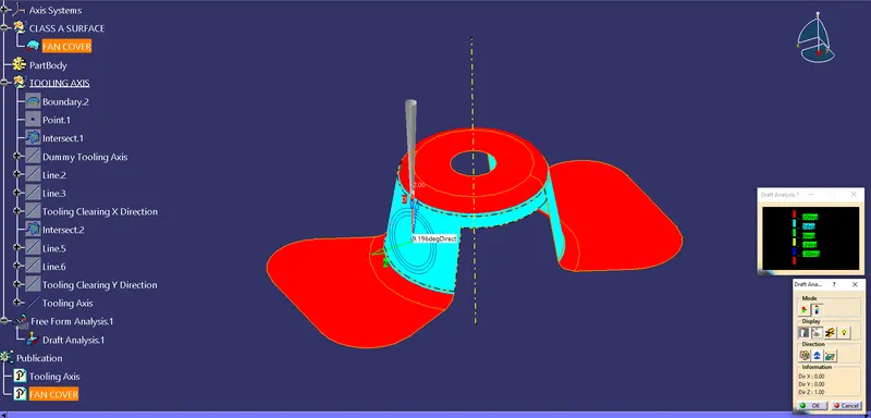
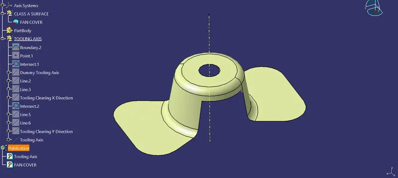
Steps Followed
- Check the connectivity using boundary option
- Insert a Geometrical set and name it a tooling axis
- Create an axis system with the point created from the boundary of the fan cover hole
- Intersect the XZ plane and fan component as a result you will get the 2 boundary lines
- Now create a dummy tooling axis along the point - direction
- Create pont - pont lines along the faces of the fan component to create the bisecting line
- The output that is the bisecting line gives us the Tooling Clearing X direction line.
- Similarly create the same for the YZ plane as well.
- The next step is to create another bisecting line with lines we got and hence we get the actual Tooling Axis
- Now publish it by selecting the tooling axis and the fan component
- Next we do the draft analysis via selecting the Feature draft analysis option from the Insert Menu