Week 11 - Final project
DESIGN OF FRONT DOOR PANEL PLASTICS TRIMS
AIM :
To design the B-Surface interior trims of Front Door Panel with the reference of A-Surface & Master Section & also to develop the attachment features of plastics which following in OEM design standards.
OBJECTIVE :
- To design the Solid parts of front door panel interior plastic trims by the A-Surface & Master Section.
- To Analysis the tooling Axis of the parts & Analyse the draft angle and tooling direction of component.
INTRODUCTION :
Automotive design is the process of developing the appearance, and to some extent the ergonomics of motor vehicles.
The designer responsible for the vehicles' interior develops the proportions, shape, placement, and surfaces for the instrument panel, seats, door trim panels, headliner, pillar trims, etc. Here the emphasis is on ergonomics and the comfort of the passengers. The procedure here is the same as with exterior design (sketch, digital model, and clay model).
DESCRIPTION :
This projects will shows the detail analysis of Design, Master section, practical knowledge on plastics with core & cavity and Tooling axis & draft analysis.
PLM of Automotive Industries :
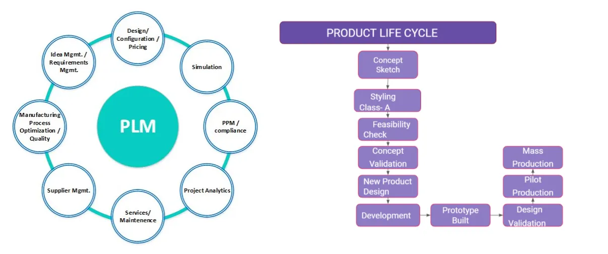
Design Life Cycle of Automotive Industries :
- Concept Sketch often freehand, that are used by designers such as architects, engineers and interior designers as a quick and simple way of exploring initial ideas for designs.
- Styling Class A design from concept sketch where industrial designers develop their design styling through the A-Surface, the physical surface the end user can feel, touch, see etc.
- Feasibility Check is an assessment of the practicality of a proposed project or system. A feasibility study aims to objectively and rationally uncover the strengths and weaknesses of an existing parts or proposed venture.
- Concept Validation is before getting a product into production and launching it to the marketplace it's critical to determine its acceptability to the marketplace.
- New Product Design which works on 3 basic principle
- Analysis
- Concept
- Synthesis
- Development is a process that creates growth, progress, positive change for the automobile parts.
- Prototype built the visual model for presentation or the knowledge (e.g) Clay modelling.
- Design Validation is a final testing process of product which you design.
- Pilot Production is also the process of validating the product with less amount of production.
- Mass Production is takes place after the validation from the customer.
A-Surface :
The sketches and rendering are transformed into 3D Digital surface modeling and rendering for real-time evaluation with Math data in initial stages. During the development process succeeding phases will require the 3D model fully developed to meet the aesthetic requirements of a designer and well as all engineering and manufacturing requirements. The fully developed CAS digital model will be re-developed for manufacturing meeting the Class-A surface standards that involve both technical as well as aesthetics. This data will be further developed by a Product Engineering team. These modelers usually have a background in Industrial design or sometimes tooling engineering in the case of some Class-A modelers. AutoDesk Alias and ICEM Surf are the two most widely used software tools for Class-A development.
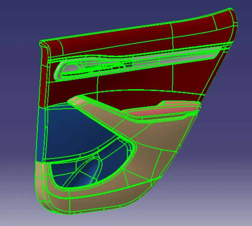
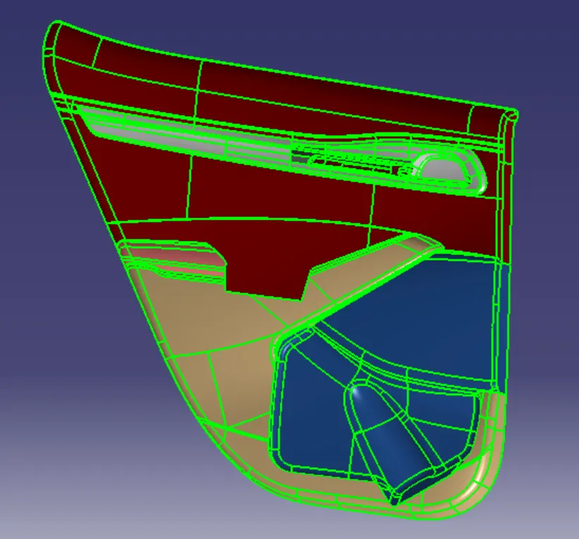
A-Surfaces of Front door panel,
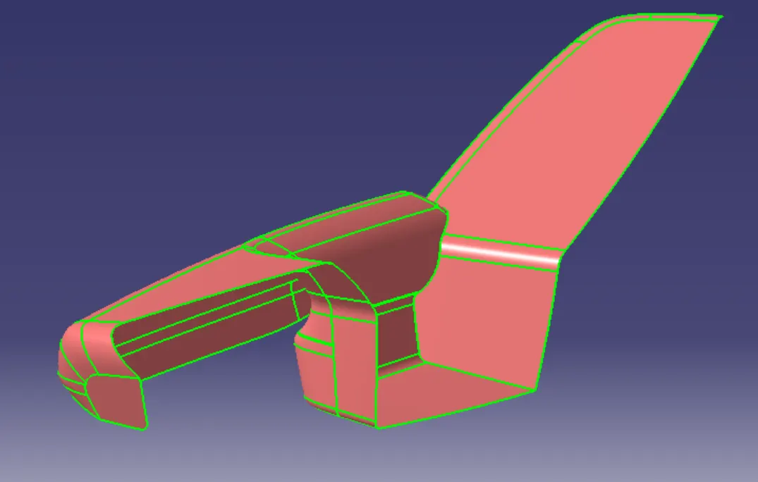
A-Surfaces of ARM REST from Front door panel,
A-Surfaces of MAP POCKET from Front door panel,
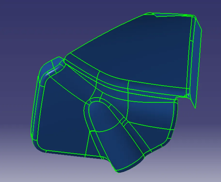
A-Surfaces of TOP SUBSTRATE from Front door panel,
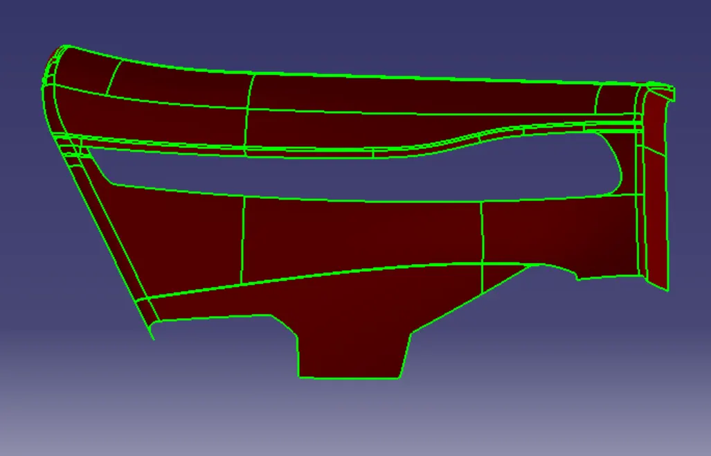
A-Surfaces of LOWER SUBSTRATE from Front door panel,
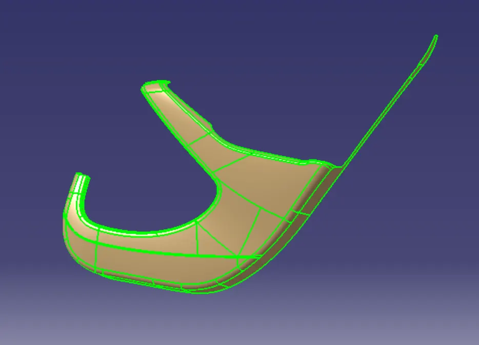
A-Surfaces of GARNISH & DOOR HAND RELEASE from Front door panel,
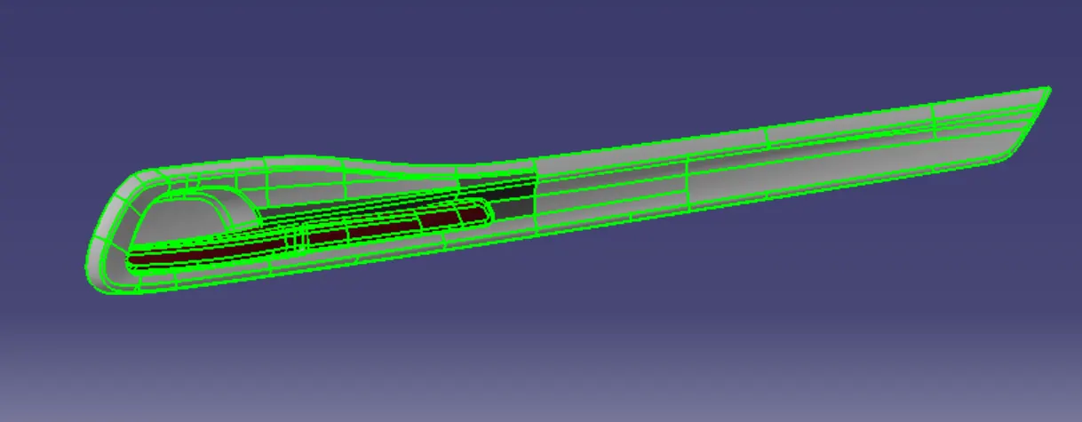
MASTER SECTION :
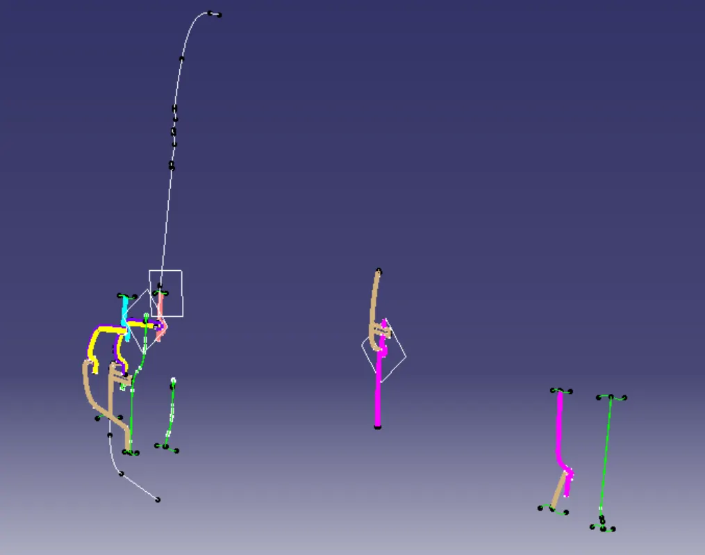
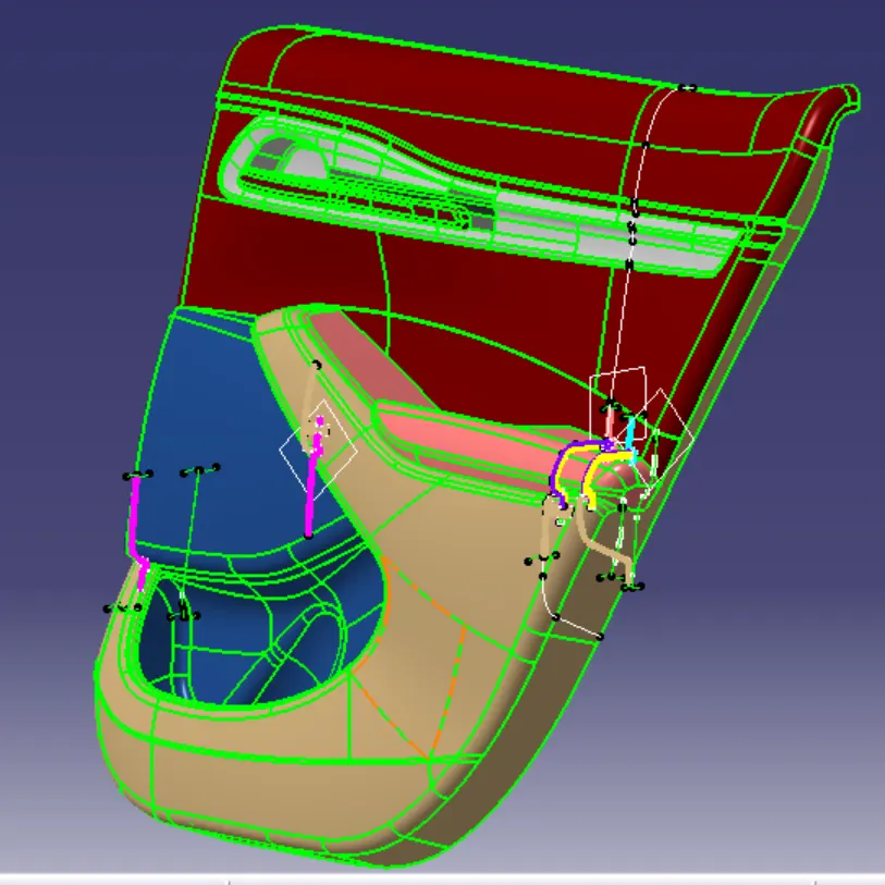
Master Section which gives the proper guides for design requirement to the design engineers.
Master Section for Front Door Panel,
TOOLING AXIS :
The tooling axis which gives the proper direction of the core & cavity for moulding the plastic component and setting the proper parting line.
Attachment features :
- As from the master section the attachment features are dog house, 4 way connector & heat stakes.
- The attachment features which follows the 3-2-1 taylor's principle.
Tooling Direction for the different parts of Front Door Panel :
Arm Rest ,
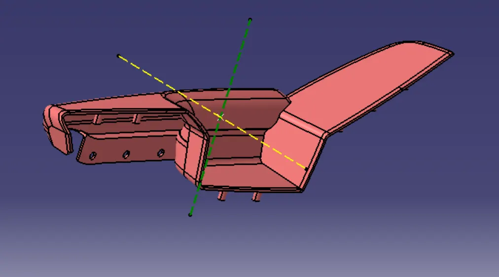
The green line tells the main tooling direction & the yellow line tells side core axis.
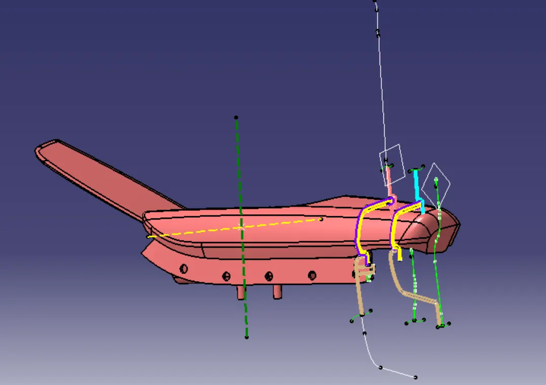
Master Section for the arm rest.
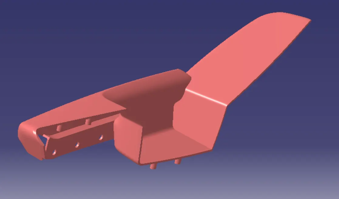
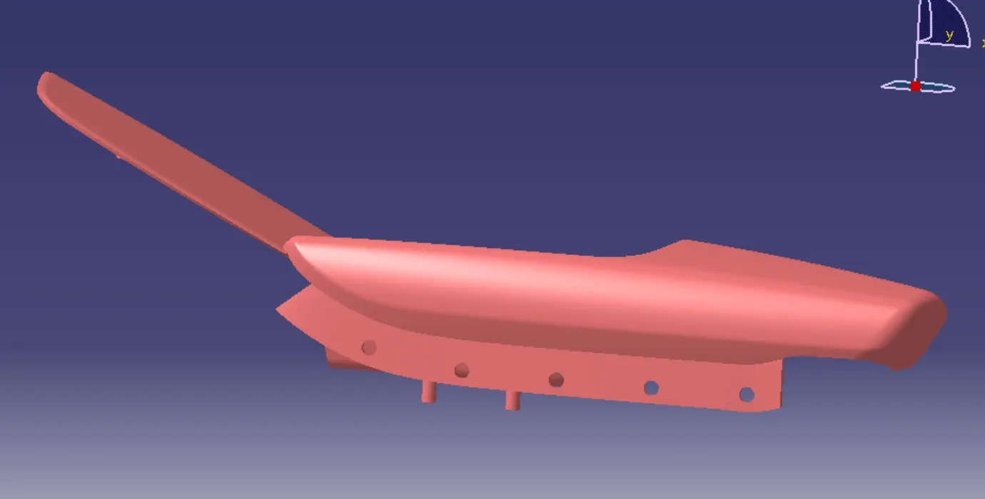
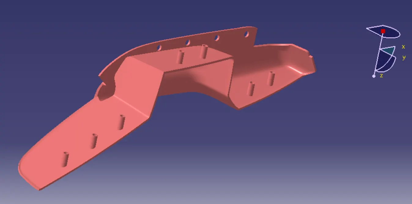
The arm rest is the part of the door panel which is used to pull or push the door.
In this part the B-surface is created on 2.5 MM thickness with the help of A-Surface and the attachment features also added to the part as per the Automotive OEM design standards.
Draft Analysis for Arm Rest :
The minimum draft required for the plastics components are 3 degree & fot the attachment features its 0.5 degree. draft analysis for the arm rest given below,
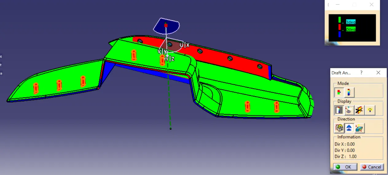
The green surface which shows the draft of more than 3 degree.
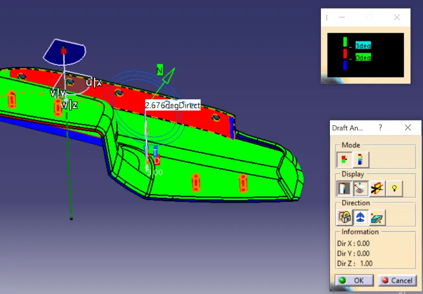
The red surface shows the draft of less than 3 degree, the red surface posses the draft of 2.67 degree which is highlighted in the above fig.
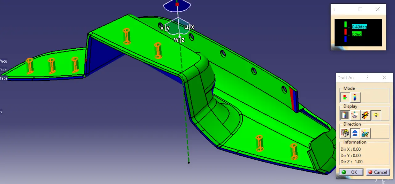
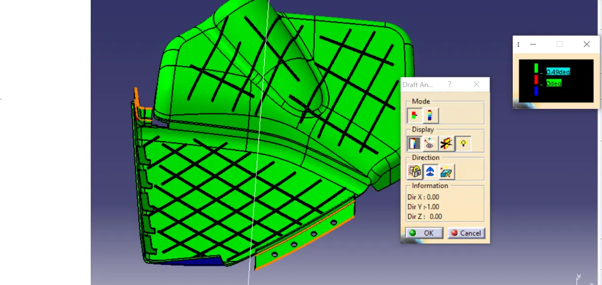
The heat stakes posses the draft of minimum 0.5 degree as per the OEM design standards.
Map Pocket :
Map Pocket which is used for temporary storage in the front door panel.
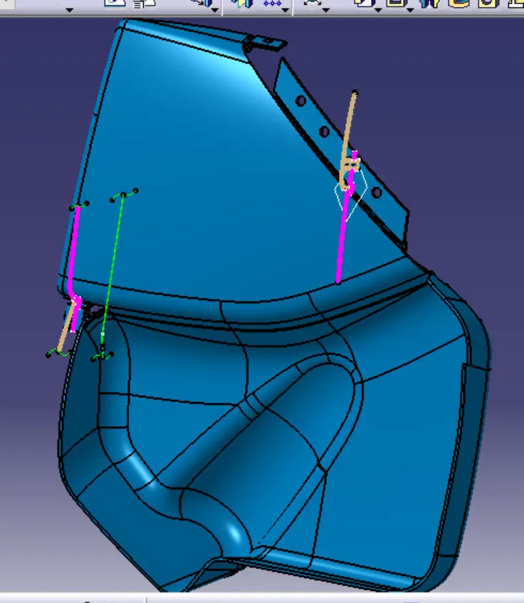
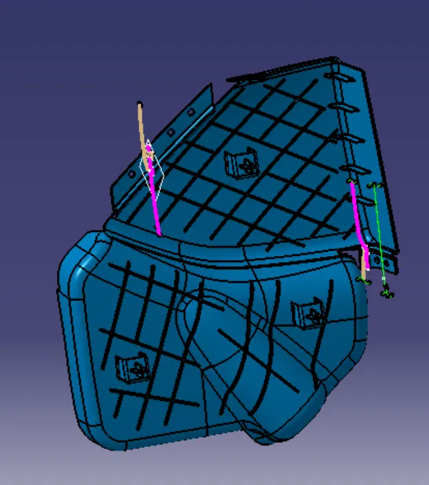
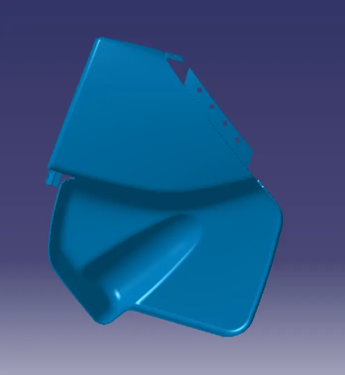
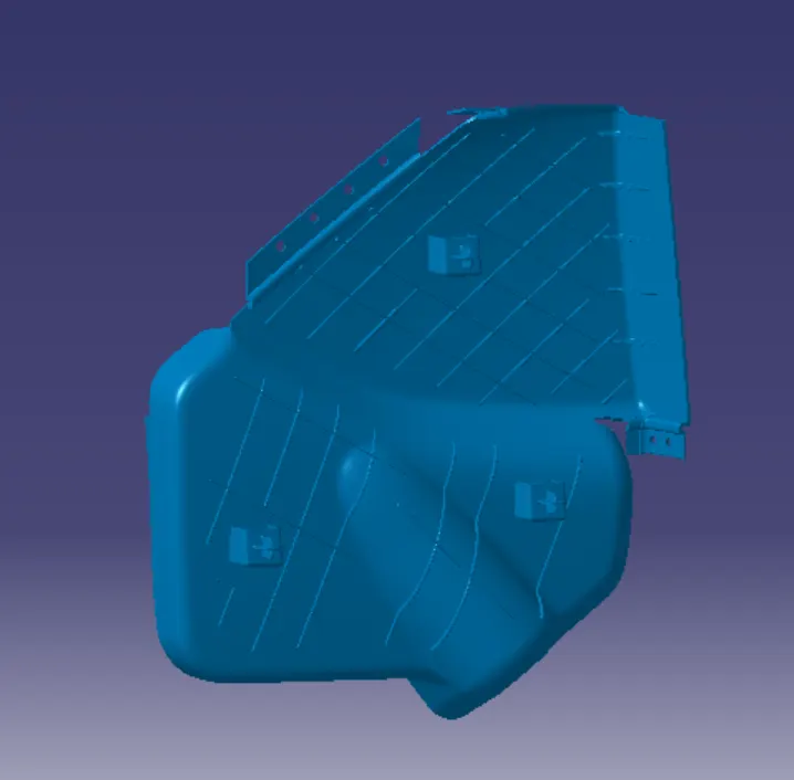
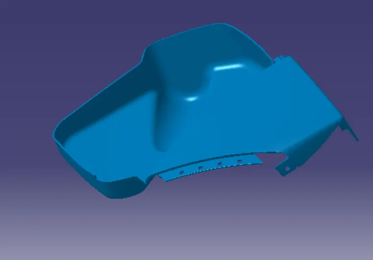
The above images shows the master section for the map pocket.
In this part the B-surface is created on 2.5 MM thickness with the help of A-Surface and the attachment features also added to the part as per the Automotive OEM design standards.
Draft Analysis for Map Pocket :
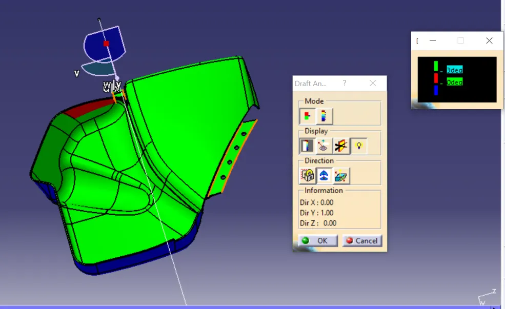
The green surface which shows the draft of more than 3 degree.
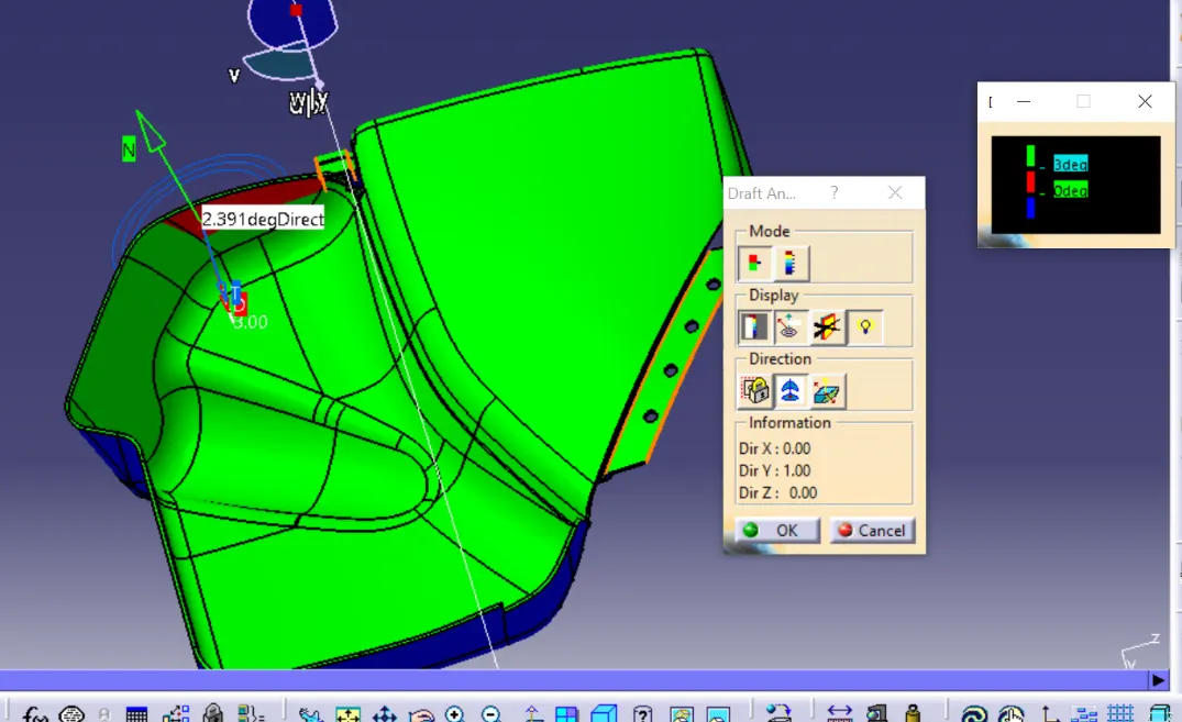
The red surface shows the draft of less than 3 degree, the red surface posses the draft of 2.39 degree which is highlighted in the above fig.
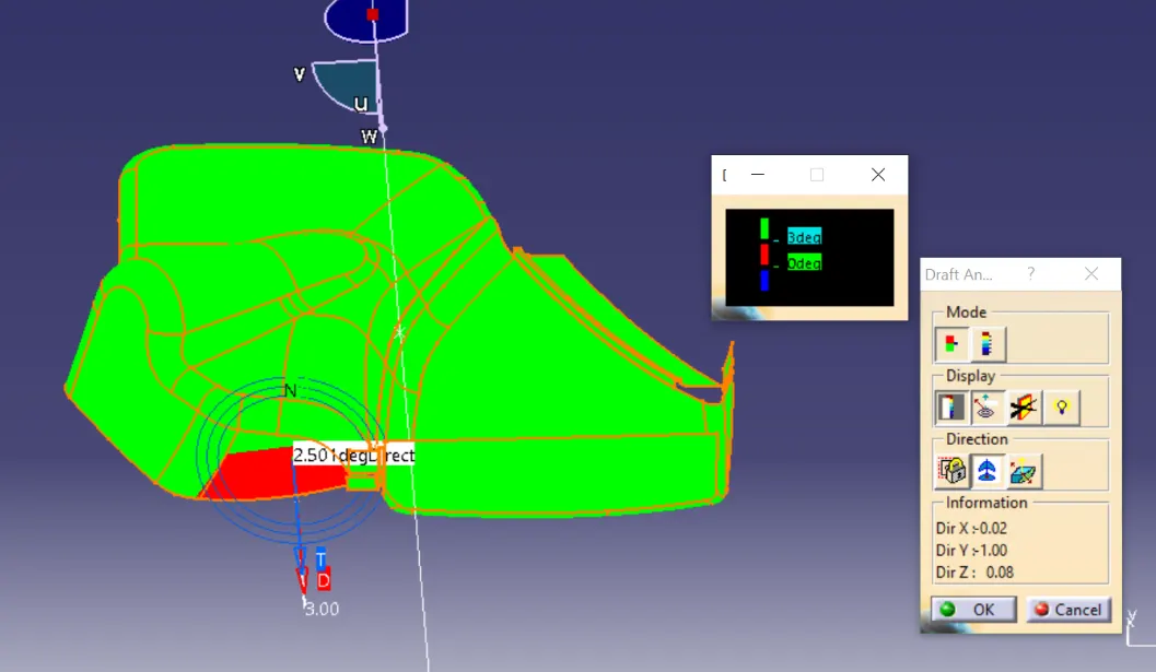
the red surface posses the draft of 2.5 degree which is highlighted in the above fig.
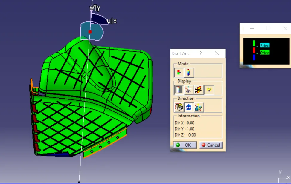
The ribs shows the draft of less than 3 degree but for the ribs the minimum draft required is 0.5 degree.
Top Substrate :
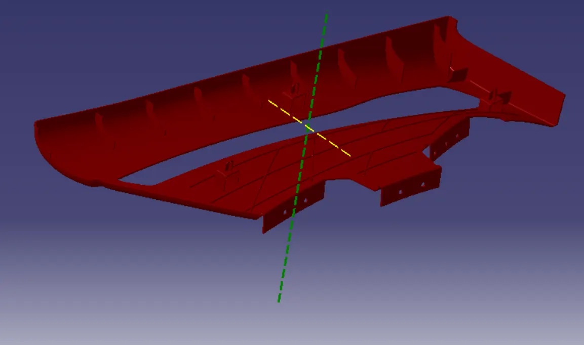
The green line tells the main tooling direction & the yellow line tells side core axis.
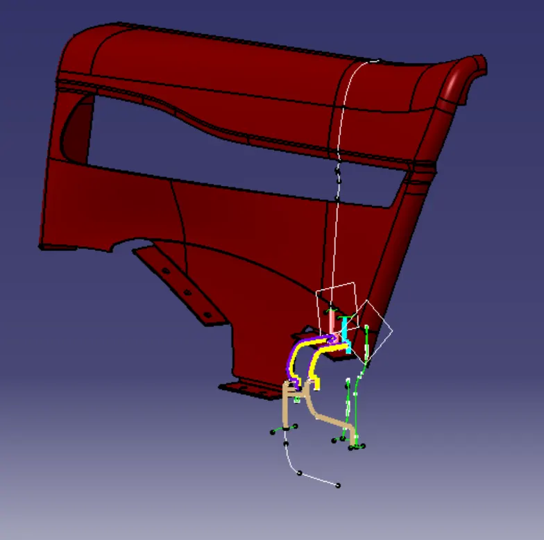
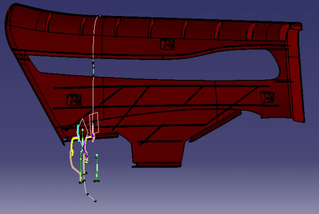
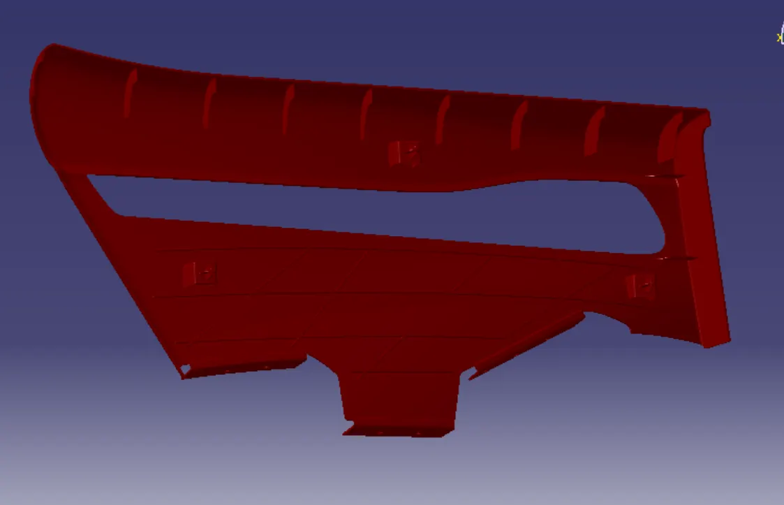
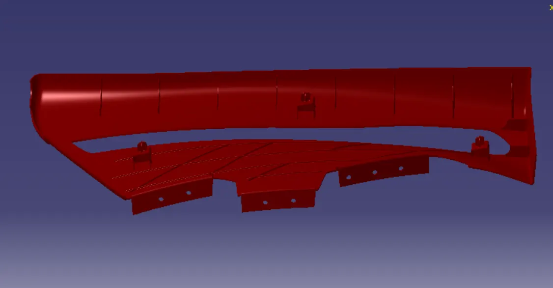
The above images shows the master section for the Top Substrate.
In this part the B-surface is created on 2.5 MM thickness with the help of A-Surface and the attachment features also added to the part as per the Automotive OEM design standards.
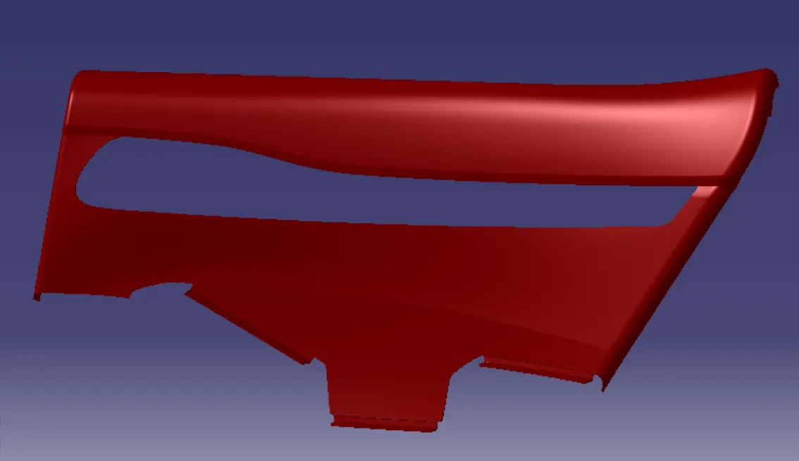
Draft Analysis for Top Substrate :
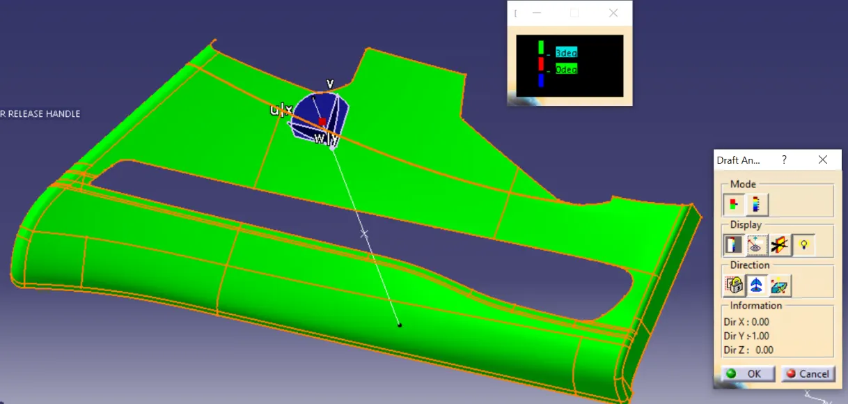
The green surface which shows the draft of more than 3 degree.
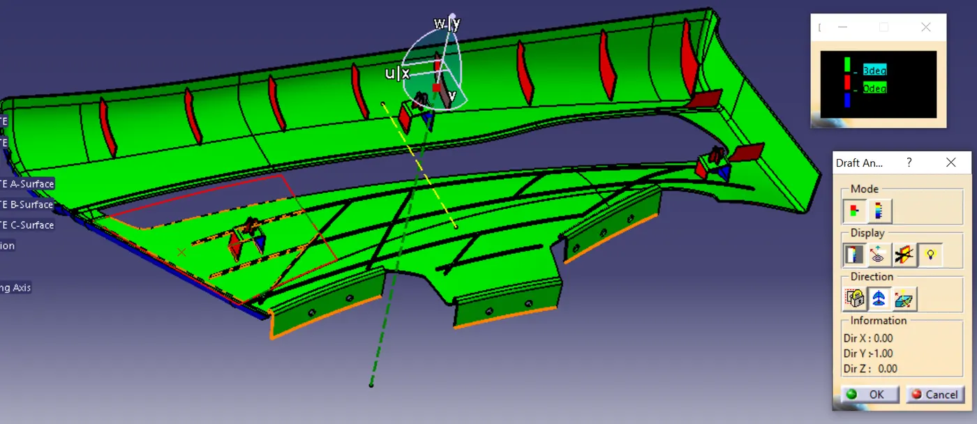
The red surface shows the draft of less than 3 degree, the red surface posses the draft of less than 3 degree which is highlighted in the above fig.
In the above fig the attachment feature shows the draft angle is less than 3 degree.
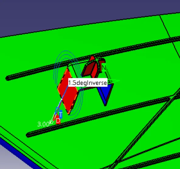
the dog house has the draft angle of 1.5 degree.
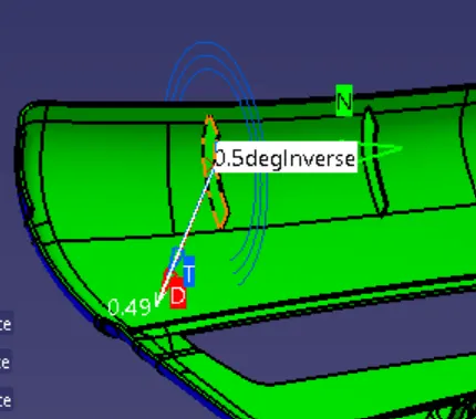
the ribs has the draft angle of 0.5 degree.
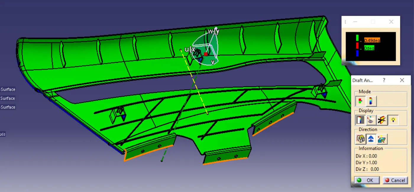
Draft Angle for ribs
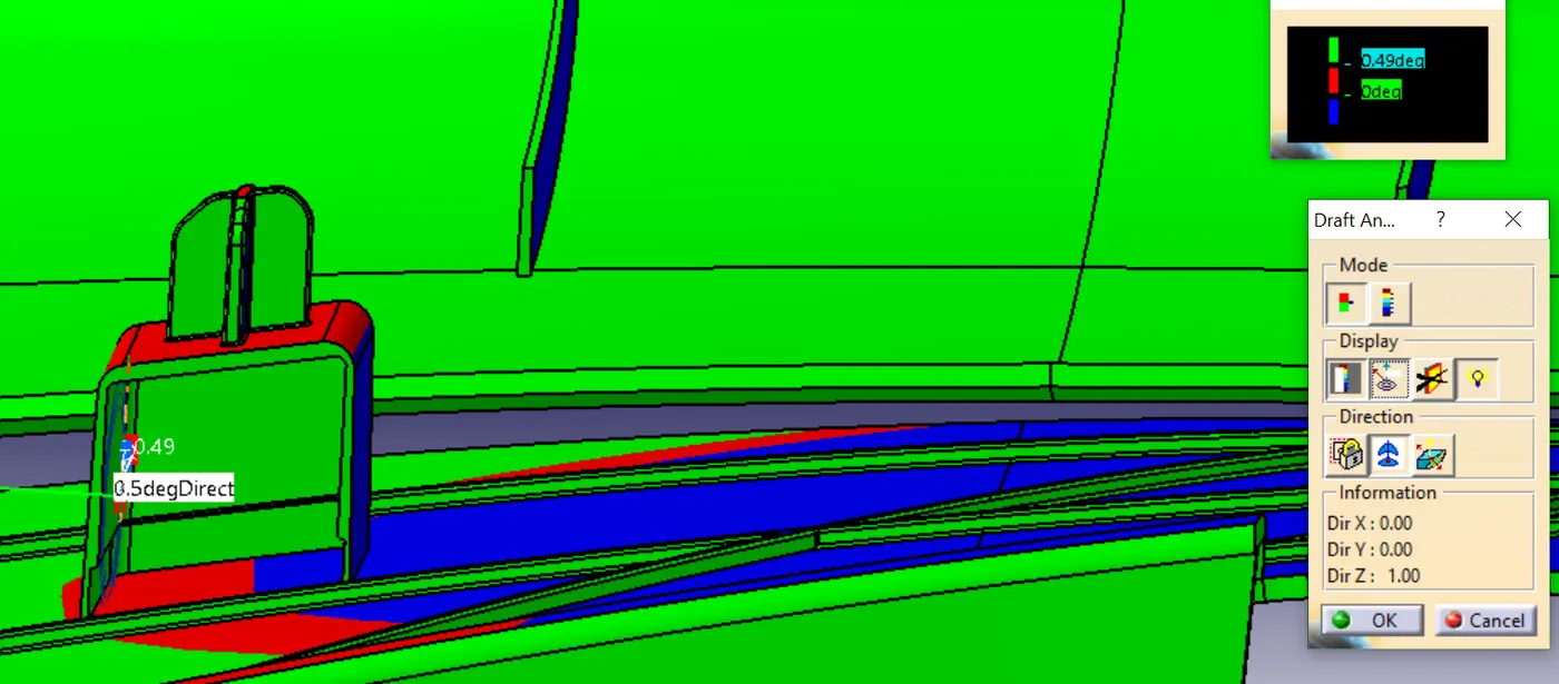
Draft Angle for side core Axis which shows 0.5 degree.
Lower Substrate :
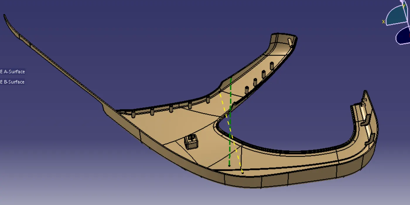
The green line tells the main tooling direction & the yellow line tells side core axis.
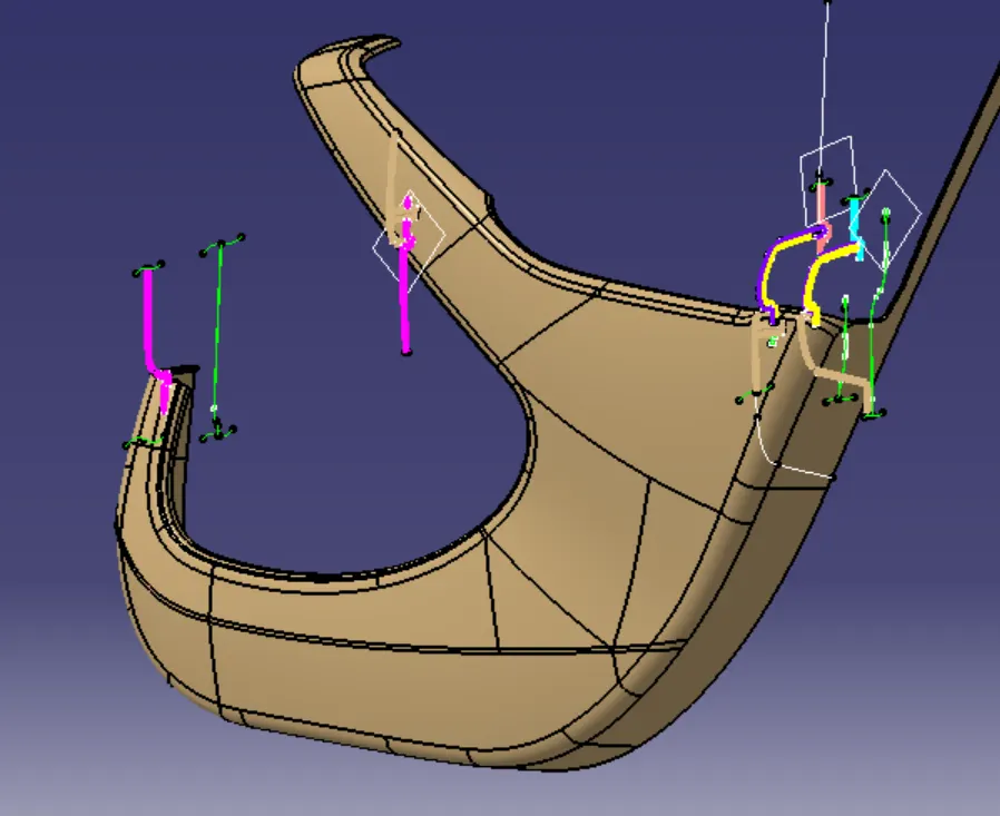
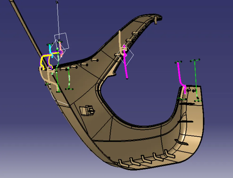
The above images shows the master section for the Lower Substrate.
In this part the B-surface is created on 2.5 MM thickness with the help of A-Surface and the attachment features also added to the part as per the Automotive OEM design standards.
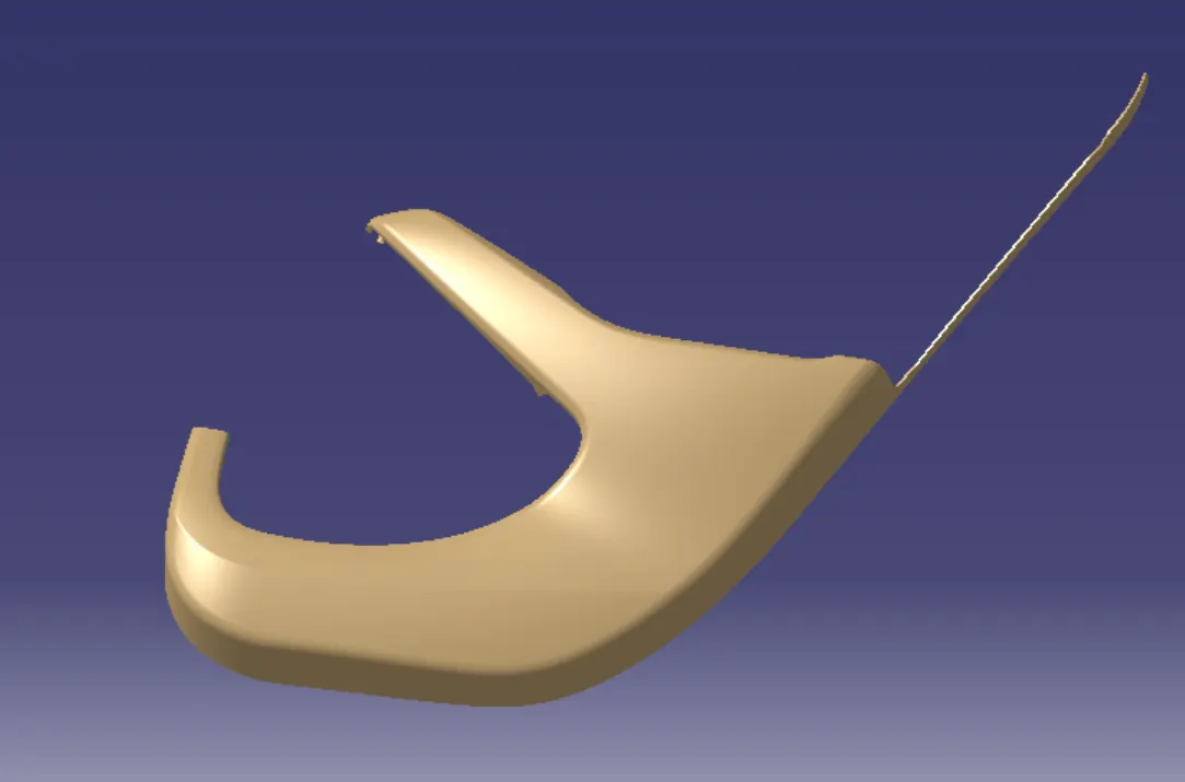
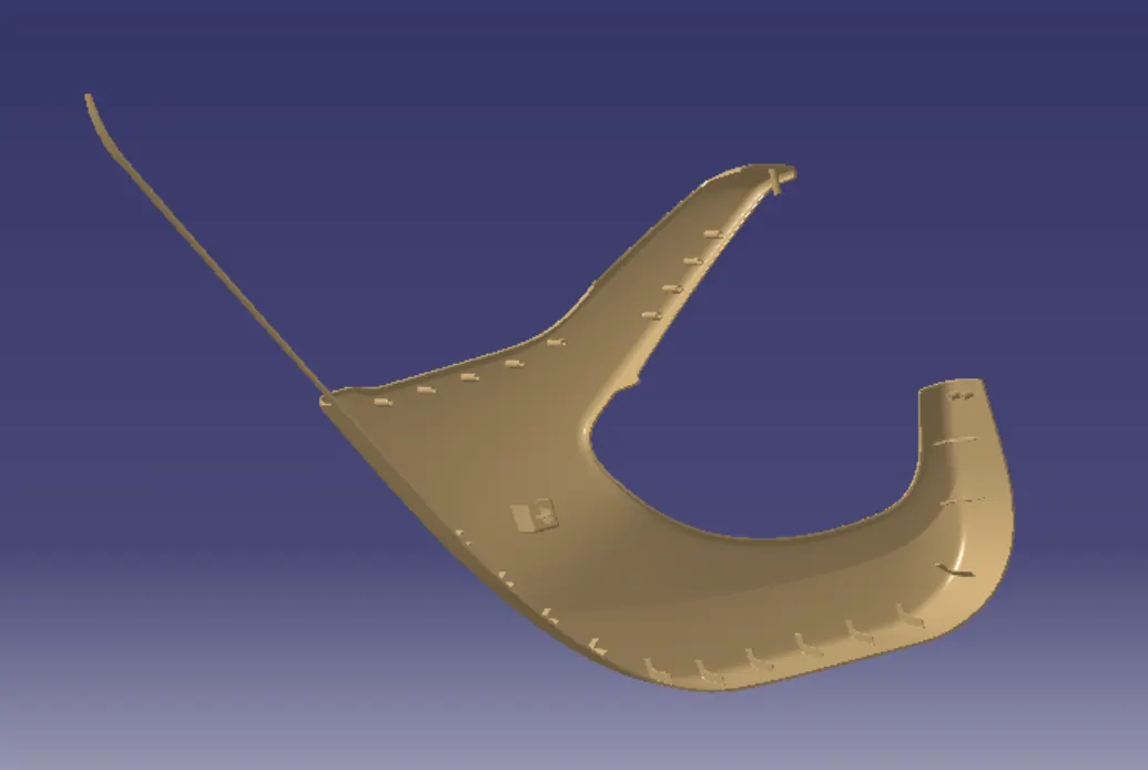
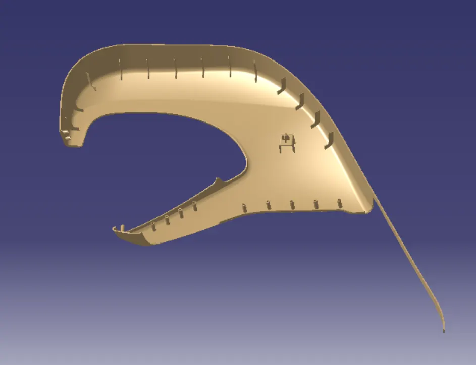
Draft Analysis for Lower Substrate :
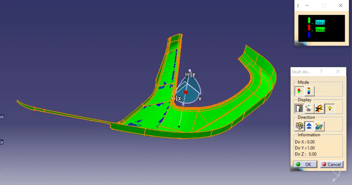
The green surface which shows the draft of more than 3 degree.
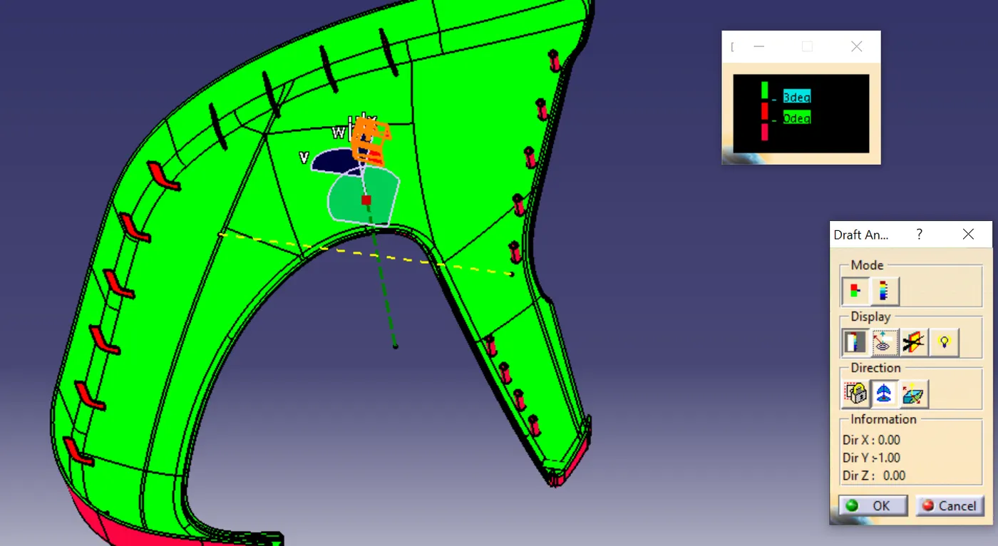
In the above fig the attachment feature shows the draft angle is less than 3 degree.
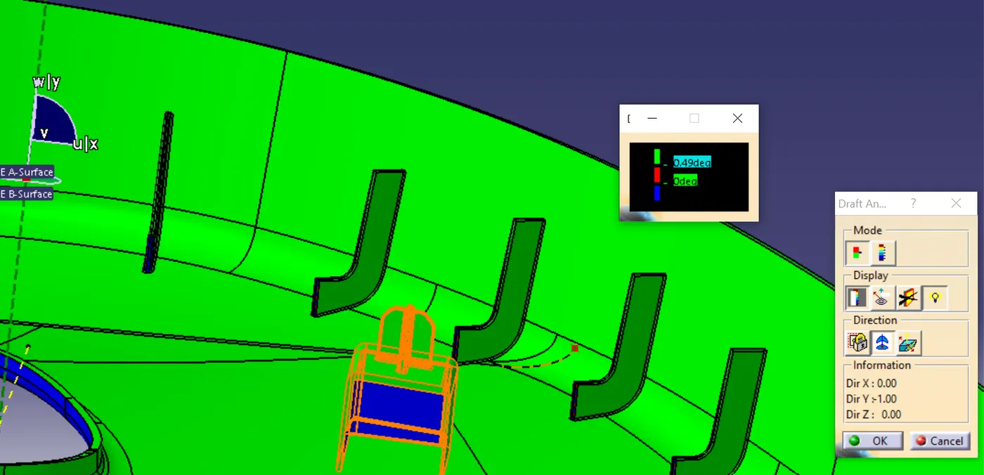
the ribs has the draft angle of 0.5 degree.
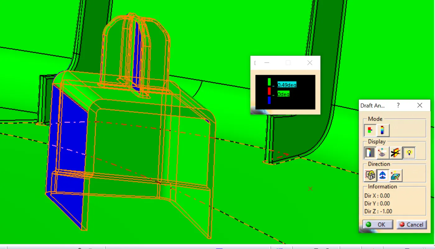
Draft Angle for side core Axis which shows 0.5 degree.
Garnish & Door hand Release :
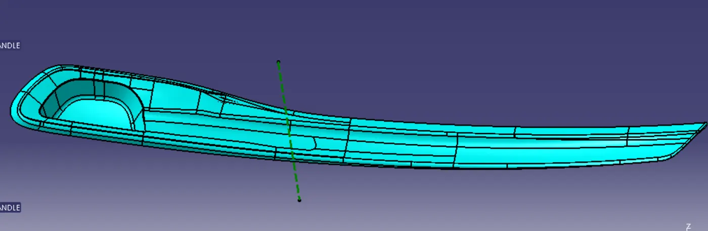
The green line tells the main tooling direction.
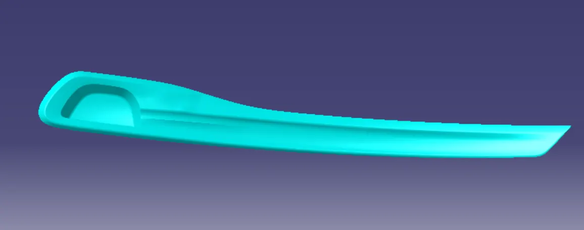
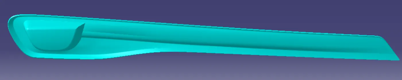
In this part the B-surface is created on 2 MM thickness with the help of A-Surface and the attachment features also added to the part as per the Automotive OEM design standards.
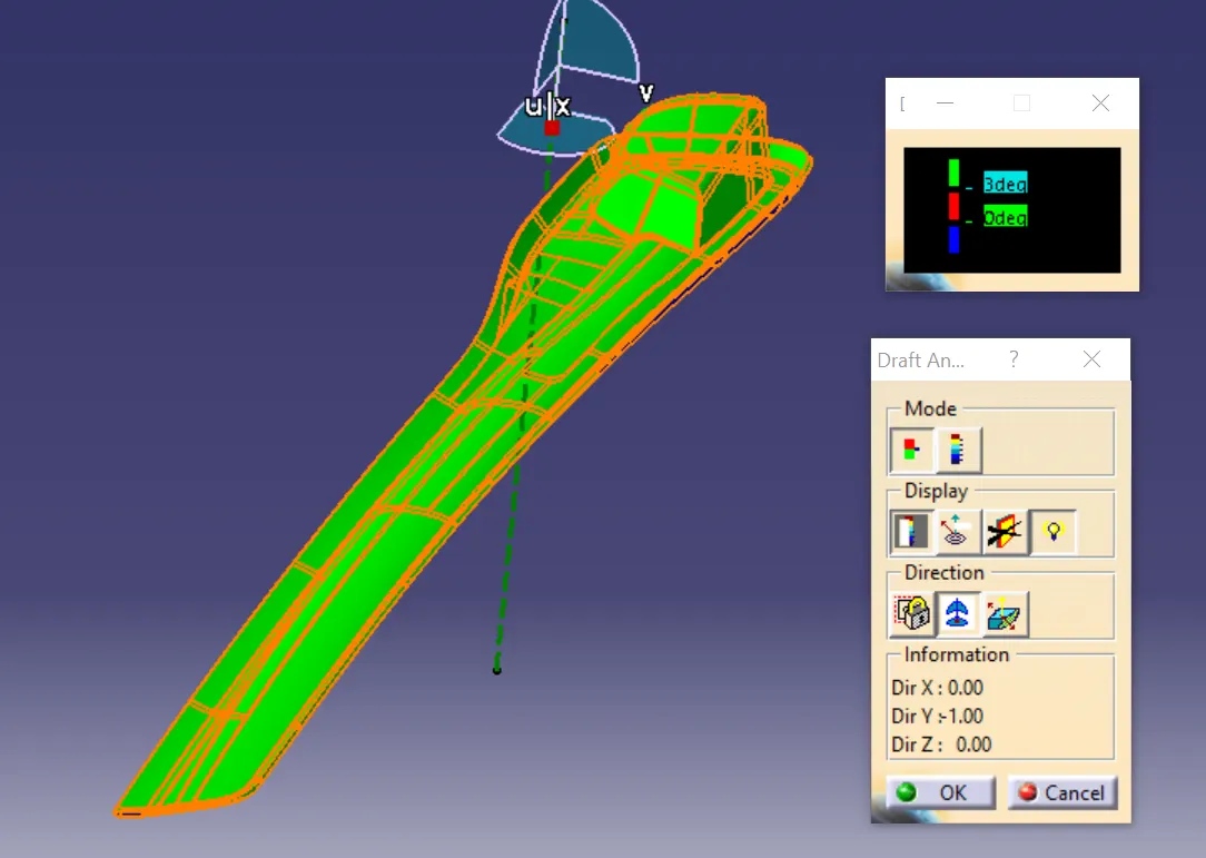
Draft Analysis for Garnish :
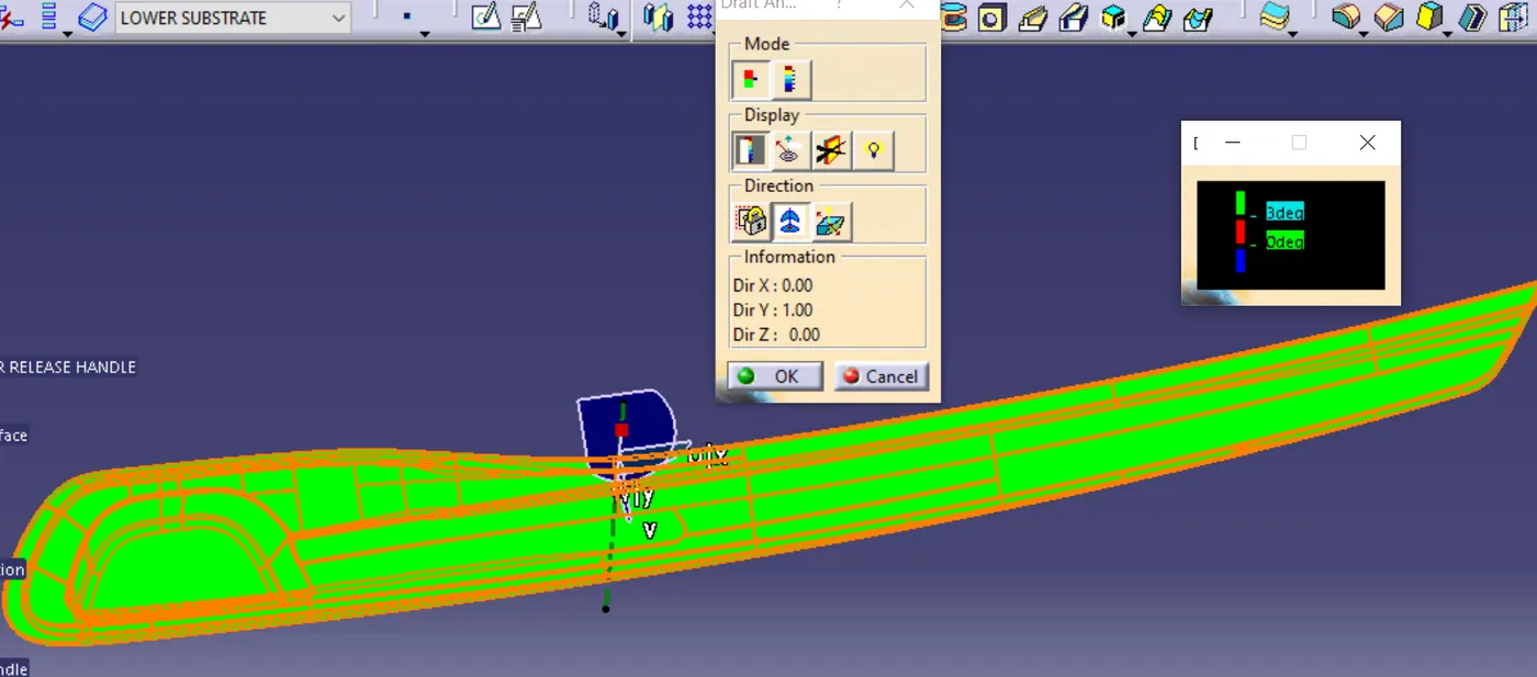
The green surface which shows the draft of more than 3 degree.
Final Part :
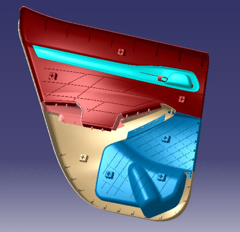
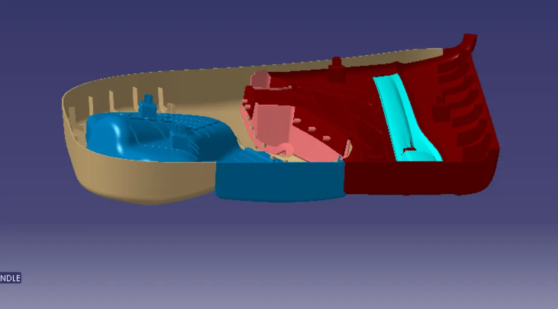
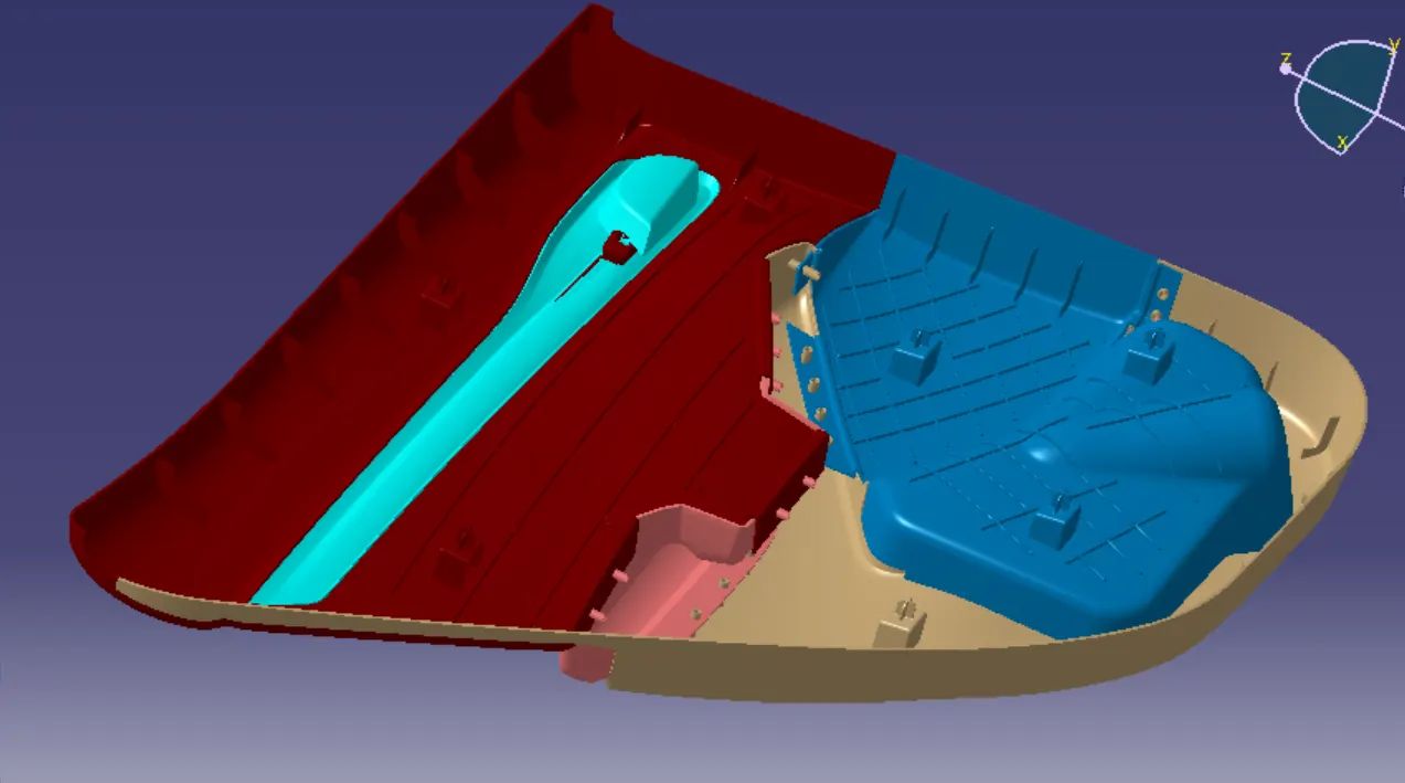
The Part to Part attachment is finally done by the heat stakes. The final front door panel is completed sucessfully & the B-Surface features are attached as per the Automotive OEM design Standards.
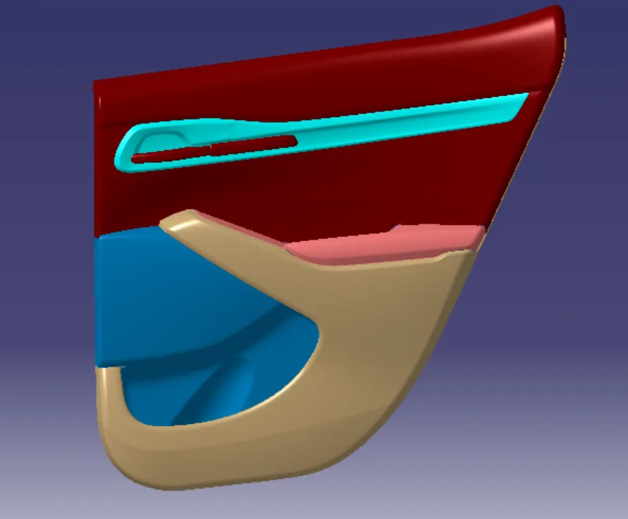
Link for the part : Interior plastics trims FRONT DOOR PANEL
CONCLUSION :
Thus todesign the B-Surface interior trims of Front Door Panel with the reference of A-Surface & Master Section & also to develop the attachment features of plastics which following in OEM design standards is successfully completed by using Catia V5.