Discretization of 3D intake manifold using GEM-3D
Aim:
Discretization of 3D intake manifold using GEM-3D
Objective:
1. Tutorial- single cyl DI add case 2 with discretization length 0.1 mm for intake runner and compare with default case 1
-
- Parameters-Torque, BSFC, max cylinder pressure
- simulation time
2. Explore tutorial no 2 (GEM3D) - “Building intake manifold from STL model”
Steps to convert 3D intake manifold using GEM 3D to 1D GT model:
Importing the plenum .stl file to GEM 3D
- Open file to open plenum.stl model.
- Select next and make sure surface radio button is selected.
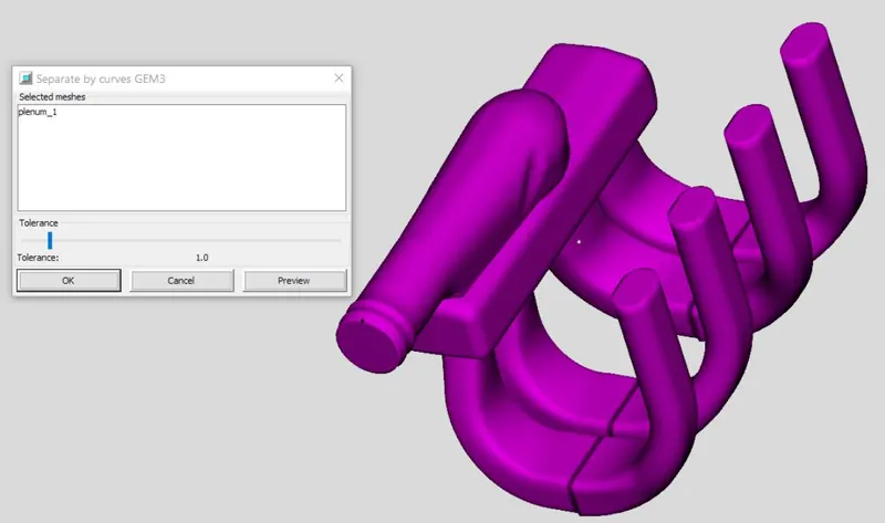
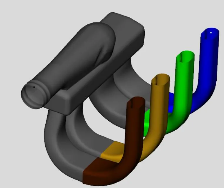
Removal of caps using selection of curves
- The inlets and ends of 4 intake runner are closed, so these caps are necessary to open for available to flow.
- Select separate by curve option, to separate geometry by parts based on the surface of object.
- Set tolerance limit to 1
- End section of runner and plenum are separated from main shape, we can delete them from model.
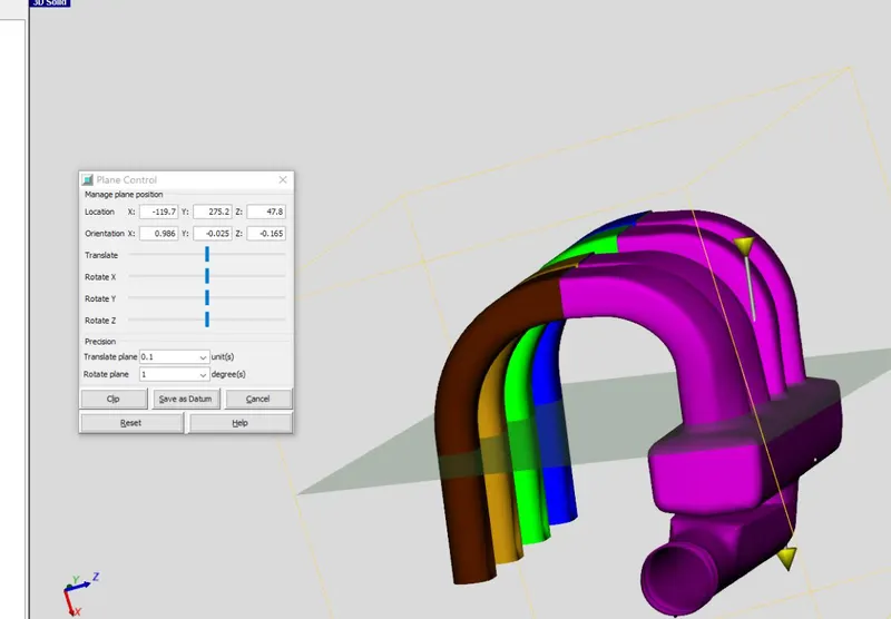
Separation of runner from manifold
- From convert tab select 3 point cutting plane.
- A cutting plane is created by clicking on three point on the model to define a plane.
- Once the plane is created, translate the plane so that it separates the runner and manifold.
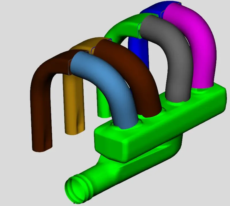
Converting runner to flow component
- Now we convert the shape to components by right clicking on it.
- Select the geometry type we would like to convert. Select pipe in case of runner.
- Assign port number.
- Keep an appropriate dimension of pipe and keep it fix till the end of the pipe.
- Repeat it for other runner ports.
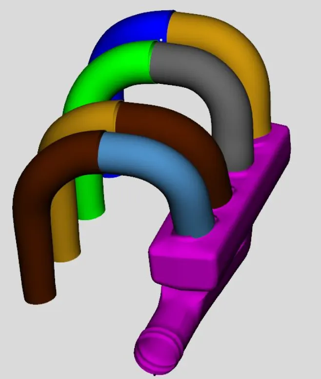
Adding orifice connection:
- To add a custom orifice, right click choose orifice connection and provide ID no.
- Give forward discharge coefficient of 0.95
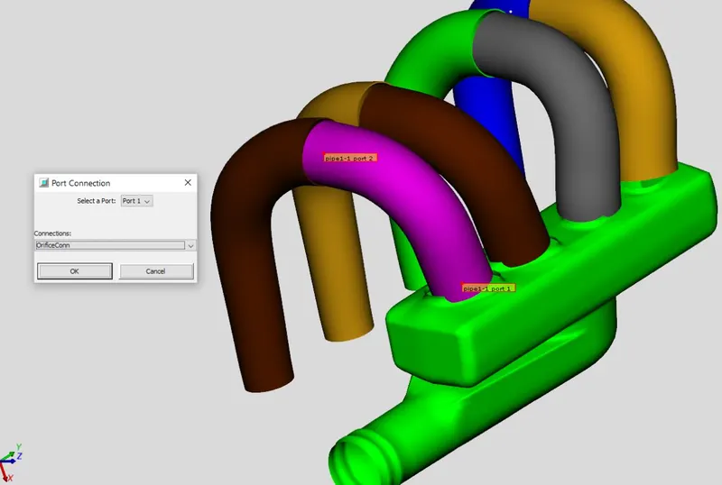
Adding subassembly connection to flow direction:
- Select the port 2 to runner end and set ID no 1. Set the flow direction to outlet.
- This helps GEM 3D to determine direction from any specified values.
- Repeat the procedure for other runners.
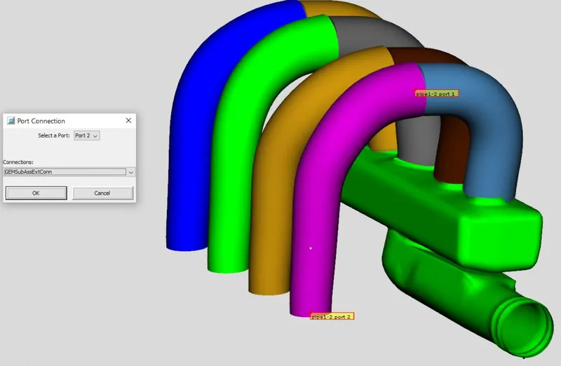
Divide manifold intake pipe and converting to flow:
- The entrance appears as a pipe section with round and D shape, then a 90 deg bend. The straight section can be converted to pipe.
- Select cutting plane from convert tab, choose pipe normal cutting.
- To separate the D section from flow split section, we drag the cutting plane till it reaches the end it joins manifold.
- The plane can be translated as far there is no abrupt change in dimension.
- Now we provide the connection to the end pipe, by right clicking on it, select add connection, select port ID 1 set flow direction as inlet.
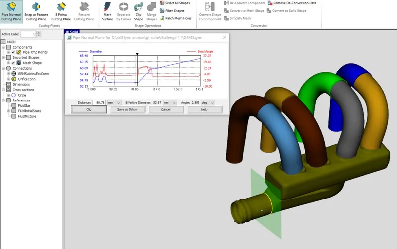
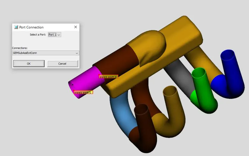
Separating 90 deg flow split from manifold
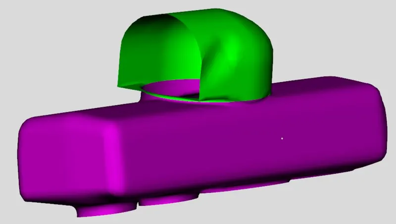
- The aim is to cut the top flow split section without cutting through manifold.
- Select 3D cutting plane from convert tab. Choose three point on the top of manifold.
- The cutting plane is rotated and adjusted in a way so that it does not cut the manifold plenum.
- The cut model should look like below
Converting manifold into smaller section and converting to flow components
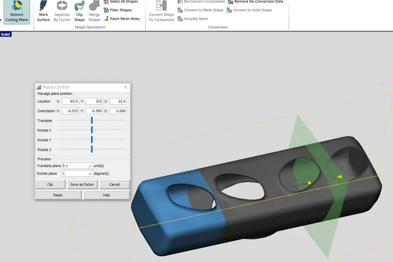
- Choose 3 points cutting plane and select one end. The plane appears and it is translated and fixed between first and second runner.
- Similar cut is made between third and fourth runner by restore plane option.
- Convert each section into flow components. Select flow split as geometry and define the ports.
Adding flow connection
- To align the pipe properly we add flow connection
- To join the runner click on flow connection face at the end of first runner, then click at the intake of second runner.
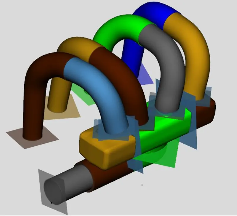
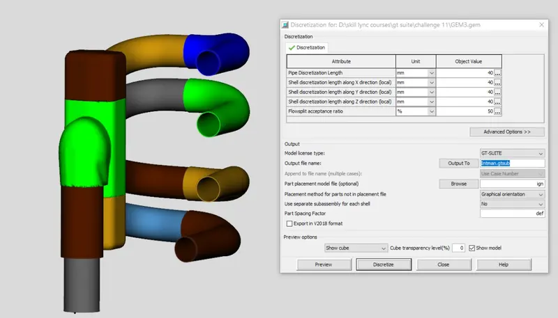
Discretized the model
- To discretized select export GT model from home tab or toolbar. This opens discretization window.
- Choose discretized length 40mm, GEM 3D will discretize and map it to GT ISE.
- Proper orientation must be maintained to discretize properly.
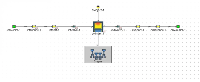
Simulation model:
6-cylinder DI engine model
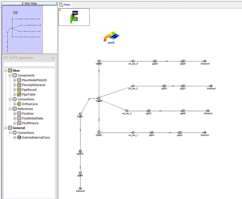
1D conversion model:
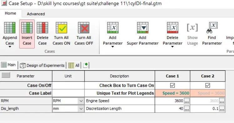
Case setup as a function of discretization length
To observe the change in discretization
GT POST:
Real time rate
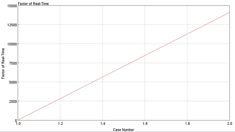
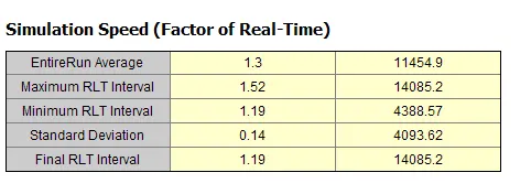
Time factor
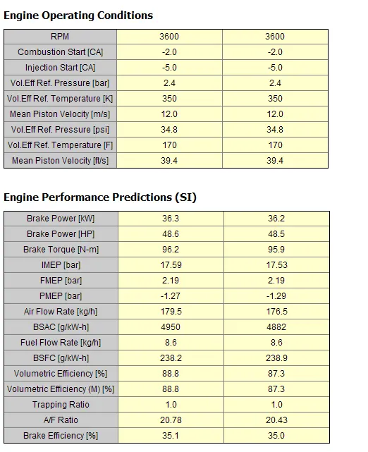
Engine performance
Conclusions:
- The average run time for case 1 is 1.3 sec and for case 2 is 1145 sec.
- The factor of real time for case 2 has increased to 14450 which is very high.
- Negligible changes of values can be observed such as BP, BT, BSFC max pressure and max temperature.
- Since no significant changes are found so the intake discretization length should be 0.44 times bore and for exhaust it is 0.55 times the bore.