Week-11 : Discretization of 3D intake manifold using GEM-3D
Objective:
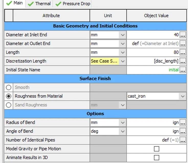
- To explore the "Tutorial- single cyl DI". In Case Setup, considering case-1 with discretization length 40 mm & case-2 with discretization length 0.1 mm for intake runner. Comparing both the results for the following parameters i.e. Parameters-Torque, BSFC, max cylinder pressure and simulation time.
- To explore tutorial No-2 (GEM3D) - “Building intake manifold from STL model”.
To explore the tutorial-single cyl Di:
Model:
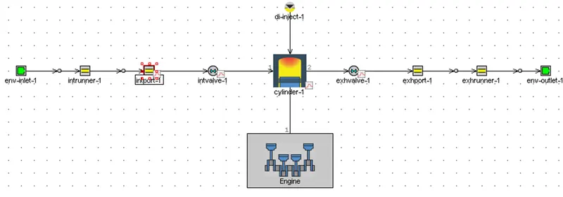
Intake runner:
Case setup:

Results:
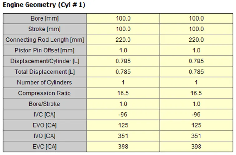
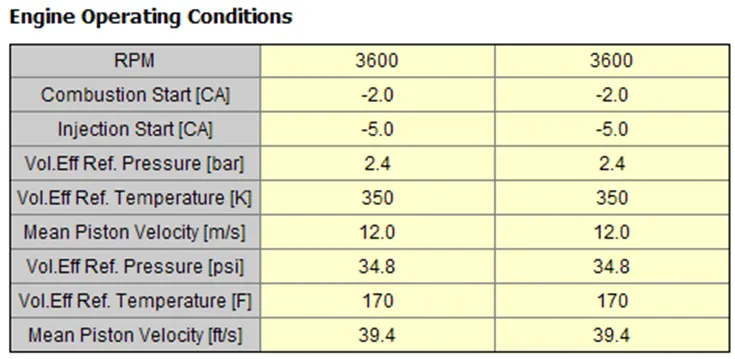
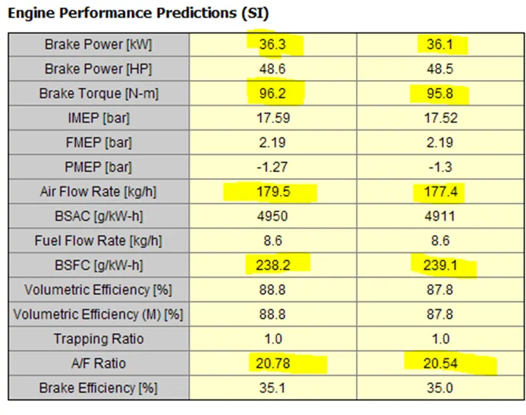
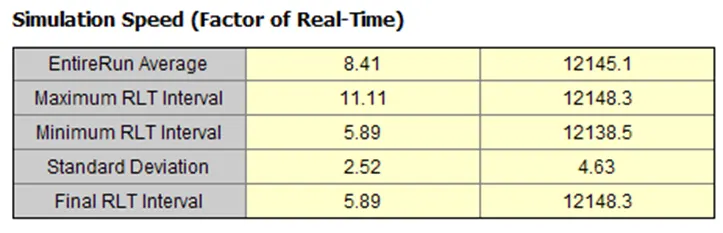
To explore tutorial no-2 (GEM3D) – building intake manifold from STL model.
Separating section by curves:
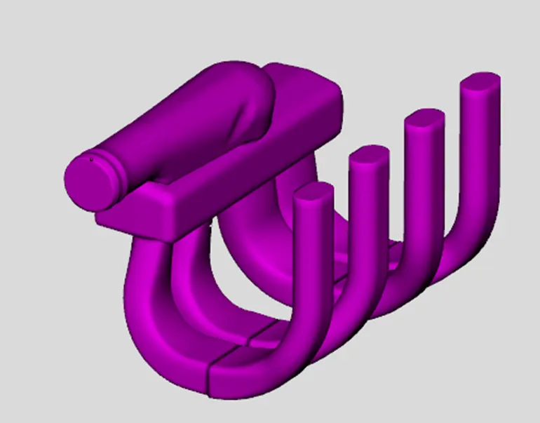
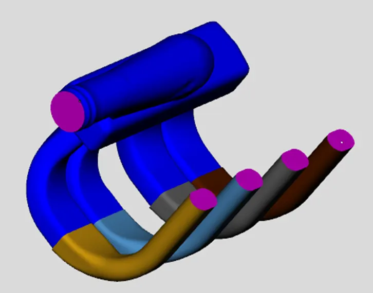
Now selected the opening where there is exchange of air and delete them.
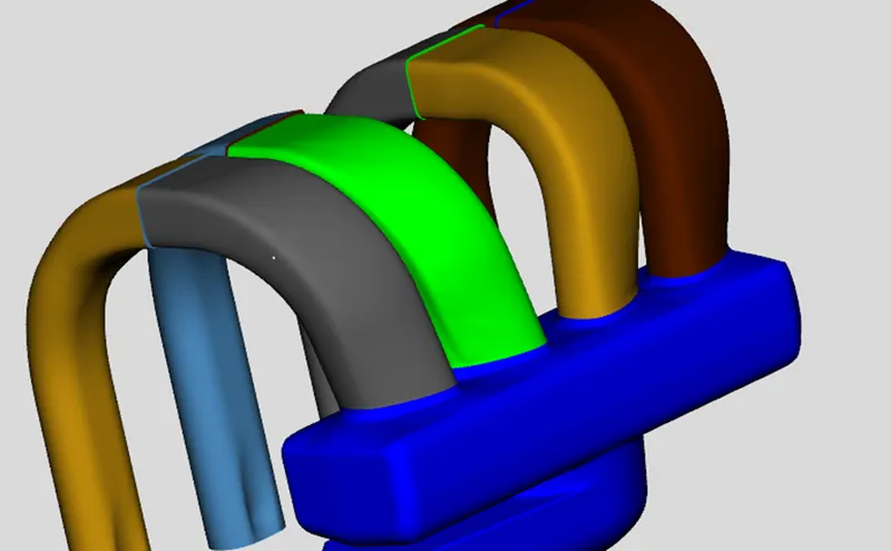
Now we have to dive the runners and other volumes. For this we use 3-point cutting plane. Select three point on the bottom surface where the runners are linked to generate the plane. Here we need to set the location such that the plane doesn’t cut the runner. Select the second part of the runner and click ‘clip’. Now we can see runners are different from plenum.
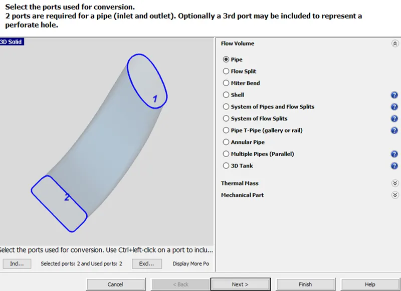
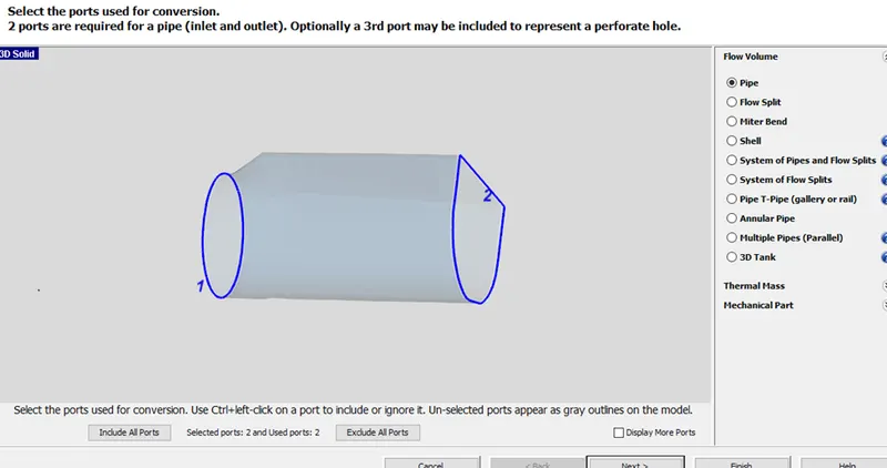
The next step is to convert the runners into pipes. Select a particular runner and right click on it we get ‘convert shape to component’.
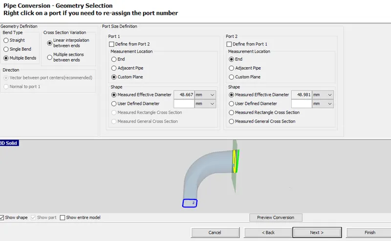
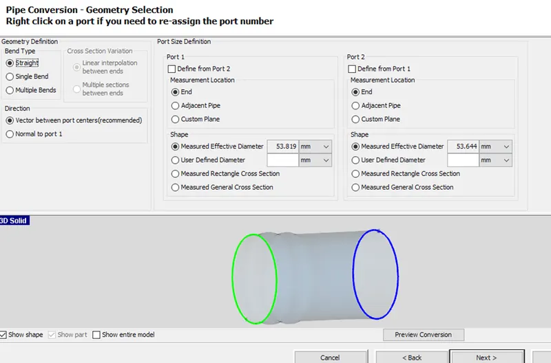
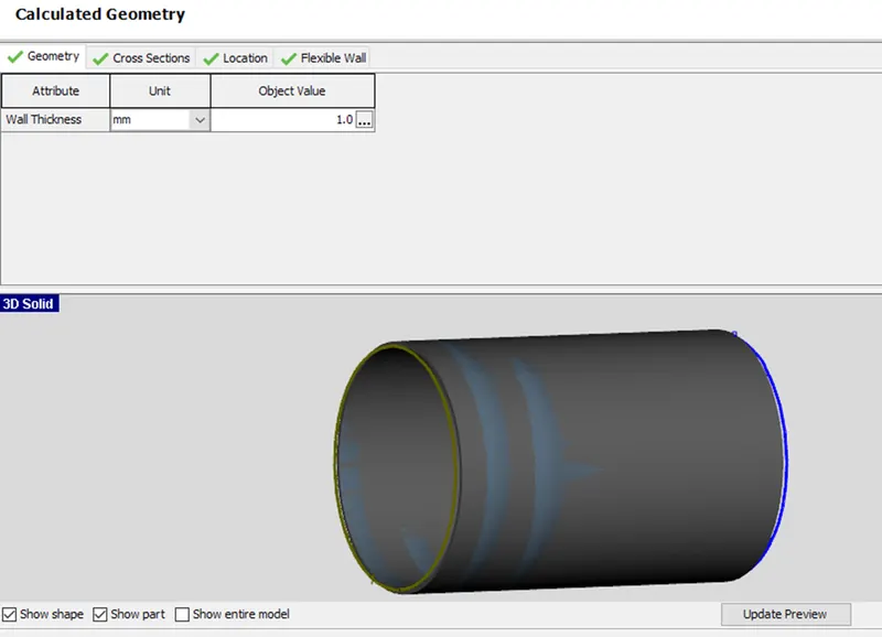
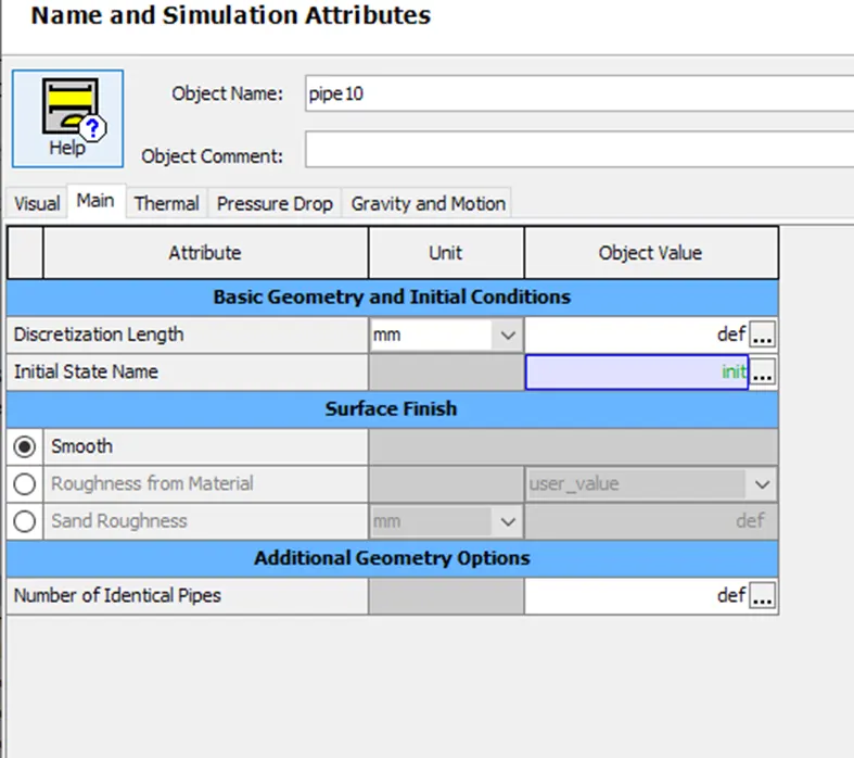
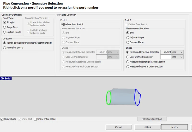
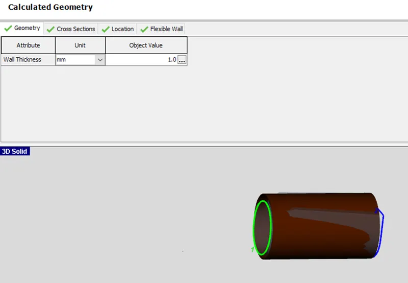
In this step we specify the bend type, cross section variation and also we specify the port size definition. We measure the approximate diameter for both the ports. The pressure temperature composition and the wall temperature are specified. Hence the pipe is generate for the first section of runner.
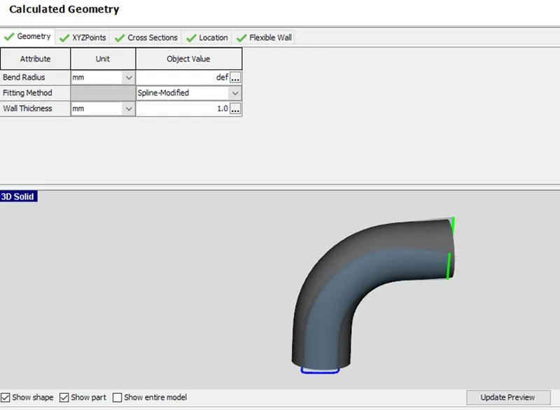
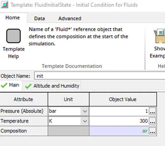
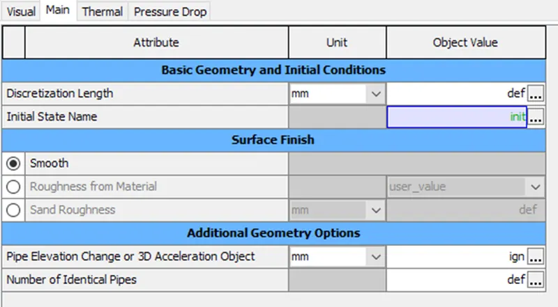
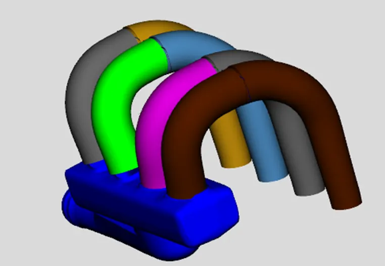
Now we need to convert the second section of the runner. The pressure, temperature, composition and the wall temperature are consider. Hence the pipe is generated for first section of runner.
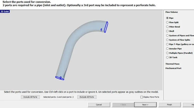
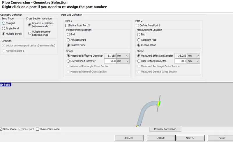
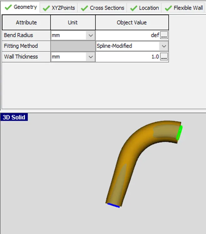
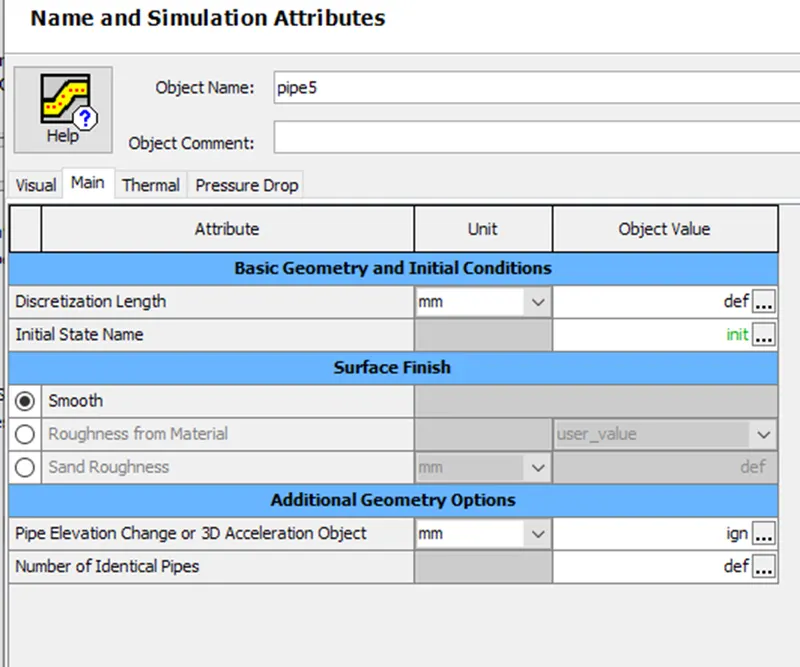
In conversion process for runners the info regarding the curved entry from the manifold was lost. His curved entry would represent a better flow transition than a default orifice connection, so manually we add an orifice connection represent.
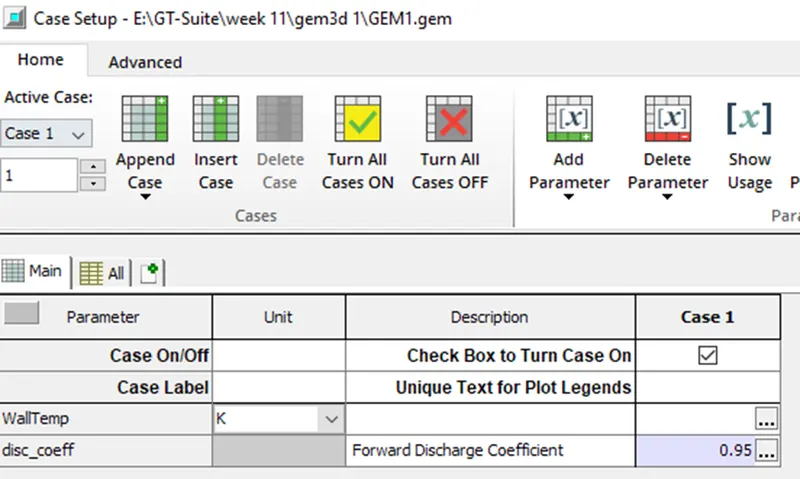
Here right click on the first region of runner, select part-1 and choose connection as ‘OrificeConn’. Forward discharge coefficient is specified as parameter for all the 4 runners. The discharge coefficient = 0.95.
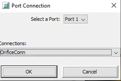
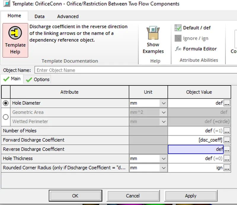
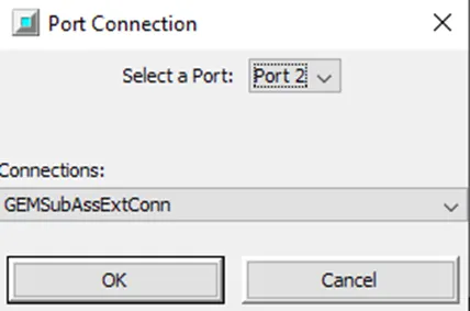
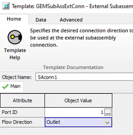
In order to make clear for GT about the intake and outlet. We need to specify the second region of runners also in the same way give the port connection accordingly. For the outlets we add ‘subassembly connection’ to clearly show difference in inlet and outlet.
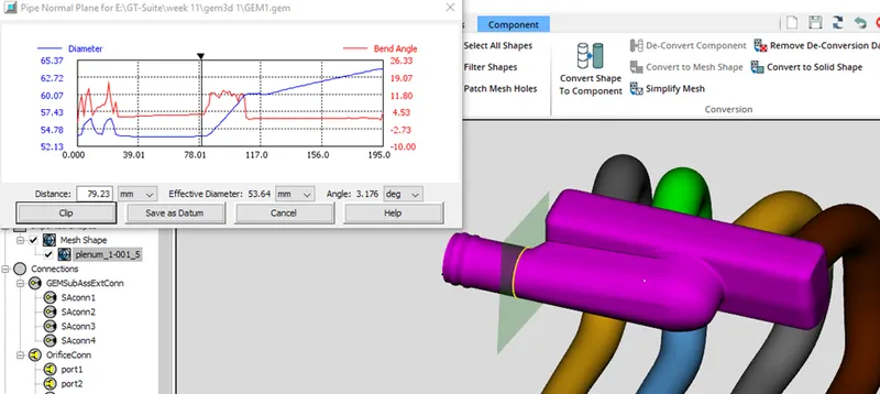
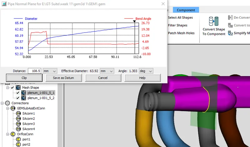
Now we need to divide the pipe section. As we can see there is same angle to the pipe at a particular place we divide the pipe selection as shown. By using pipe normal cutting plane we select the pipe region.
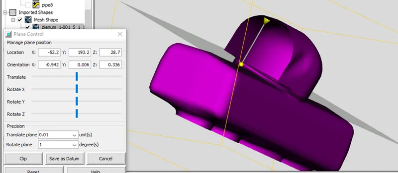
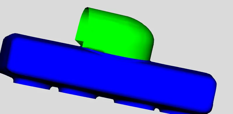
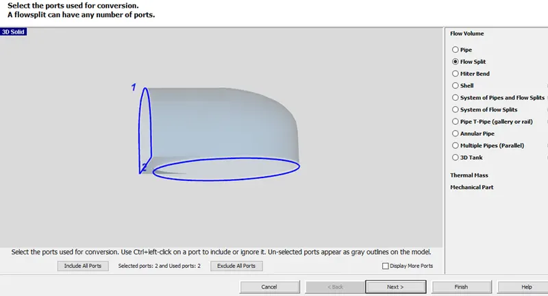
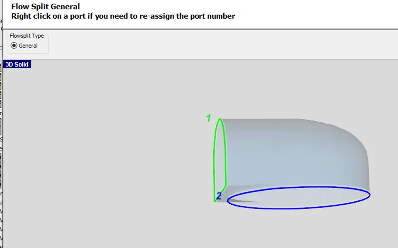
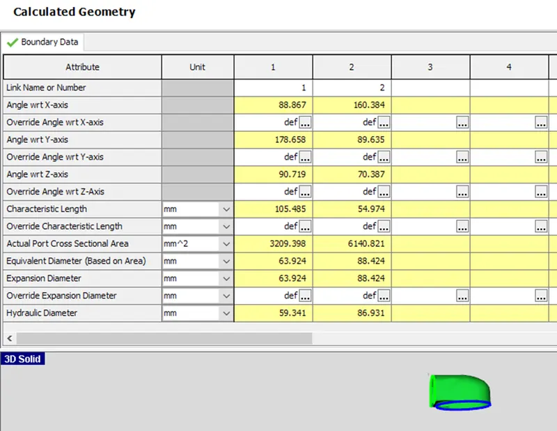
The only mesh shape left to be converted is the manifold section. Rather than converting the entire thing into a flow split, we want to manually divide it to get better resolution and accuracy in the GT-SUITE flow model. Manual discretization involves making cuts to divide up the large mesh shape into smaller mesh shapes and converting those into flow splits
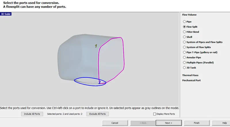
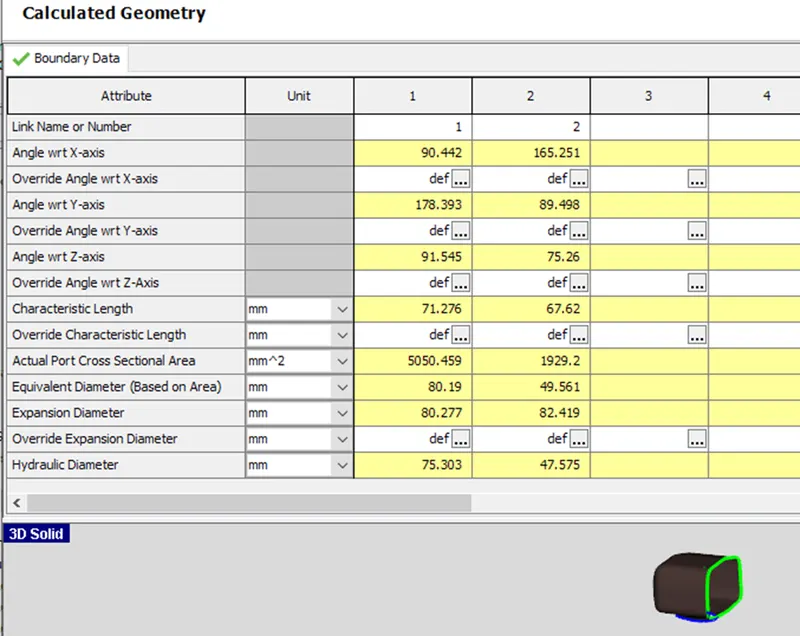
Next, we will convert the center section into a flow split. Right-click on it and select Convert Shape to Component. Select Flow split from the select the conversion geometry pane. Again, all open ports will be identified. Let's make sure the port numbers start with the entrance flow (port 1), then go to the manifold end sections (ports 2 and 3), then to the runners (ports 4 and 5).
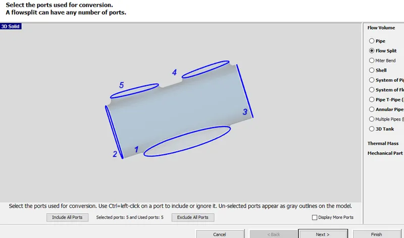
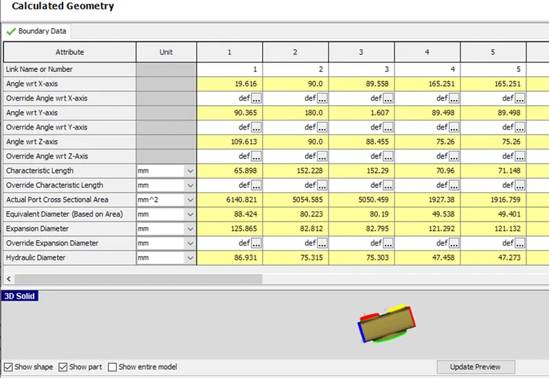
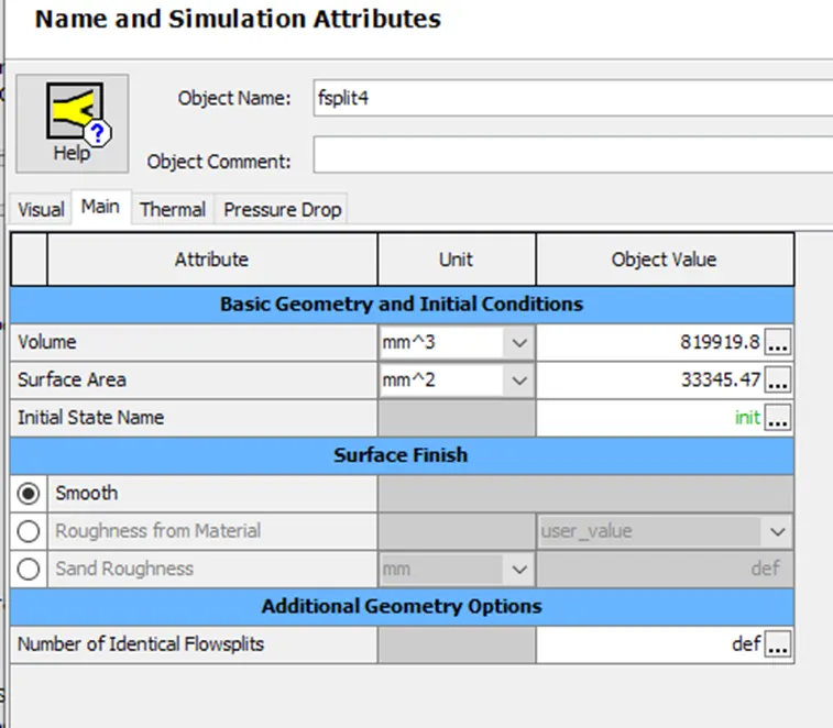
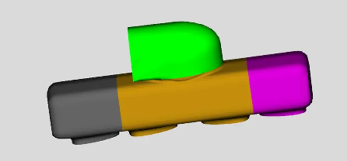
Add flow connections:
During the process of converting meshes to components, we created several pipes which do not align perfectly. To remedy this, we can use the flow connection operation to join the runner sections at the top of the manifold. To do this, select Flow Connection > Flow Connection from the Connections group under the tab Flow. This will show available surfaces for adding flow connections, as shown below. To join the runners together, click on the flow connection face at the end of the first intake runner, then click on the flow connection face at the end of the second intake runner. The sections should join together, as shown in the screenshot below.
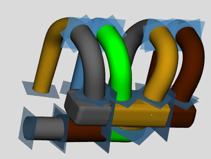
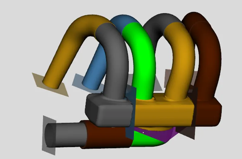
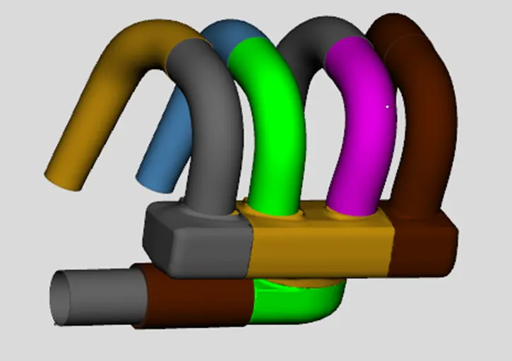
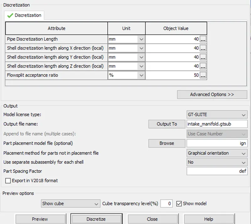
Now we need to discretize the model. Before we discretize the model we should do the orientation and then discretize.
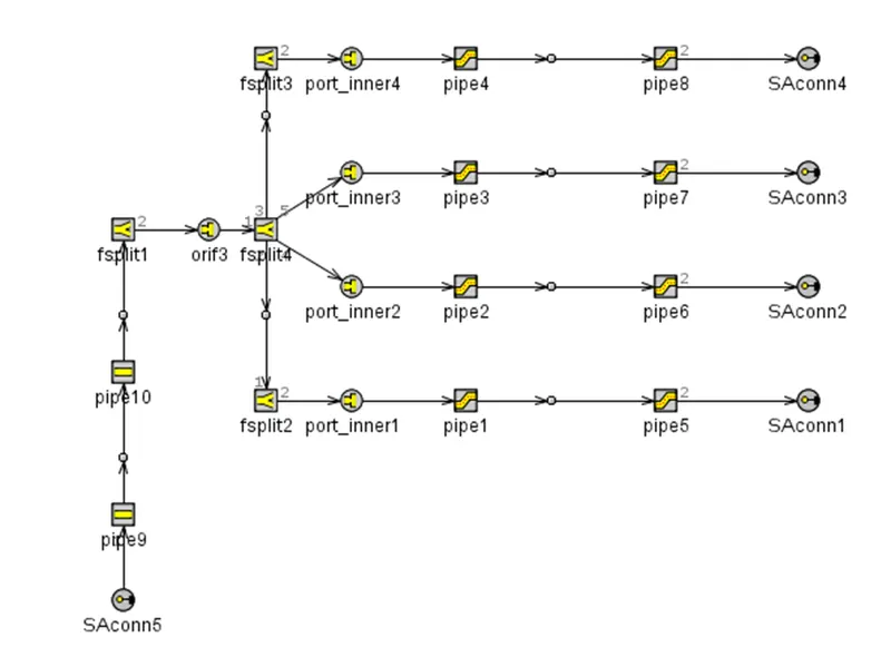
Now the 3D model is converted to 1D model. We need to align the connection is a systematic way. Hence we get the below 1D model as output.
Conclusion:
Therefore, the intake manifold is built from the STL model.