Week-11 Challenge: Braking
Dear team,
i am using online version of matlab so consider my matlab current version format.
- ENERGY REQUIRED FOR BAKING BASED ON A DRIVING CYCLE:-
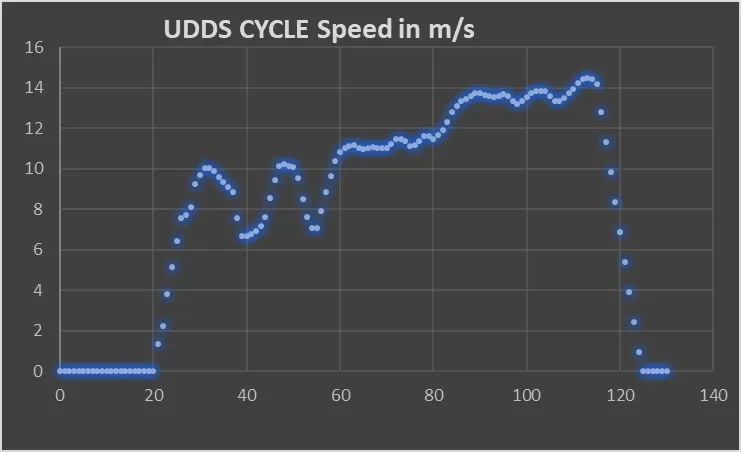
The driving cycle taken into consideration is the UDDS cycle which stands for Urban Dynamometer Driving Schedule. Although the data is taken for a total driving time for 1370s, for simplicity sake on 150s of driving time is considered. The speed which is in miles per hour has been converted to meters per second.
The drive cycle is given below.
The equation for kinetic energy from braking is given as,
Where,
m = Mass of the vehicle in Kg.
Vi = Initial speed of the vehicle in m/s.
Vf = Final speed of the vehicle in m/s.
From the drive cycle 10 braking points were obtained. The mass is set at a constant 1500 Kg. The energy required for braking is given in the table below.
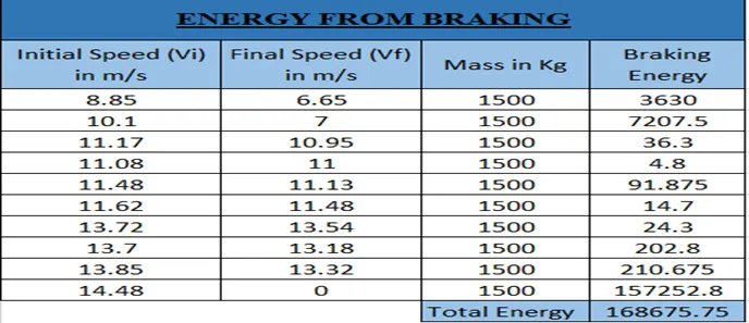
Therefore the total energy required for braking is 16.8 KW.
Please find the attached excel sheet.
2)
Let us consider the torque speed characteristics.
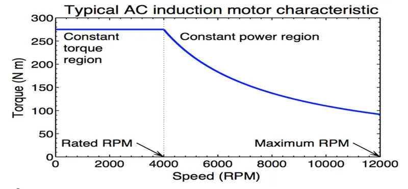
From this curve we have two region, constant torque and constant power region. At the start the motor achieves peak torque till it reaches a certain motor speed range from where it will rapidly drop. The reason due to the drop in torque is due to the motor shaft reaching critical speed and the area where the peak torque is constant is known as the constant torque region of the motor. The region where the torque decreases is known as the constant power region as the power generated by the motor will be at it's peak.
Since the torque produced at the constant power region is very low, it is not possible to develop enough braking torque in this region. The braking torque produced increases as the speed decreases.
In electric vehicles, two types of braking systems are used electric brake system and mechanical brake system.
Electric Braking System: In electrical braking, the winding of the motor is used to produce a braking torque. A braking torque is developed during the braking operation. This braking torque opposes the motion of the rotating member or shaft. This is achieved by suitably changing the electrical connections of the motor. The motor operates on a speed–torque characteristic, depending upon the method of braking employed.
Mechanical Braking System: In mechanical braking, the frictional force between the rotating parts and the brake drums produces the required braking. To achieve this, mechanical equipment, such as brake linings and brake drums, are required. Whether electrical or mechanical, the braking of the drive should stop the motor at the specified point of time and position.
3)
%Defining Speed & Torque
speed = linspace(0,1000,300);
torque = linspace(0,700,300);
%Defining Motor Constants
kc = 0.1;
% Copper Loss constant
ki = 0.001;
% Iron Loss Constant
kw = 0.0001;
% Windage Loss Constant
Cm = 25;
% Motor Loss Constant
%obtaining 2-D Grid fpr Speed & Torque
[X,Y] = meshgrid(speed,torque);
Powerout = X.*Y;
% Calculating output power
Totalloss=((Y.^2).*kc)+(ki.*X)+((X.^3).*kw)+Cm;
%Total Loss Calculation
inputpower =Powerout+Totalloss;
% Calculating input power
Z=Powerout./inputpower;
% Efficiency Calculation
%Defining Efficiency levels for contouring
EL=[0.70,0.72,0.75,0.77,0.79,0.80,0.81,0.82,0.83,0.84,0.85,0.86,0.87,0.88,0.89,0.90,0.91,0.92,0.93,0.95];
%Plotting the Efficiency wrt speed & Torque
contourf(X,Y,Z,EL)
colorbar
xlabel('Speed (rpm)');
ylabel('Torque (N.m)');
title(' Efficiency Contour');