Week-11 Challenge: Braking
- For a defined driving cycle, calculate the energy required for braking.
For a defined drive cycle of the week 2 challenge and a vehicle of 1000KG of mass
@ first 10 secs
We have braking from Sec 4 (start braking) to Sec 8 (stop) à deceleration
Braking Energy = 0.5(m)(dv)2
Braking Energy = 0.5(1000)(13.8)2 = 95220 Joule = 26.45 Wh
@ next 20 secs
We have a braking from sec 21(start braking) to sec 29 (stop)
Braking Energy = 0.5(1000)(22.2)2 = 246420 Joule = 68.45 Wh
@ next 30 secs
We have braking of sec 40 (start braking) to sec 60 (stop)
Braking Energy = 0.5(1000)(11.111)2 = 61727.1605 Joule = 17.1464 Wh
|
My drive cycle |
|
|
Time (s) |
Speed (m/s) |
|
1 |
0 |
|
2 |
4.166666667 |
|
3 |
8.333333333 |
|
4 |
13.88888889 |
|
5 |
9.722222222 |
|
6 |
5.555555556 |
|
7 |
4.166666667 |
|
8 |
0 |
|
9 |
2.777777778 |
|
10 |
6.944444444 |
|
11 |
10.55555556 |
|
12 |
13.88888889 |
|
13 |
16.66666667 |
|
14 |
15.27777778 |
|
15 |
11.11111111 |
|
16 |
12.77777778 |
|
17 |
13.33333333 |
|
18 |
16.66666667 |
|
19 |
18.05555556 |
|
20 |
19.44444444 |
|
21 |
22.22222222 |
|
22 |
19.44444444 |
|
23 |
17.22222222 |
|
24 |
15 |
|
25 |
11.66666667 |
|
26 |
8.333333333 |
|
27 |
5.555555556 |
|
28 |
2.777777778 |
|
29 |
0 |
|
30 |
4.166666667 |
|
31 |
5.555555556 |
|
32 |
7.777777778 |
|
33 |
9.166666667 |
|
34 |
10.27777778 |
|
35 |
12.77777778 |
|
36 |
12.77777778 |
|
37 |
13.88888889 |
|
38 |
16.66666667 |
|
39 |
15.27777778 |
|
40 |
15.27777778 |
|
41 |
15.27777778 |
|
42 |
13.88888889 |
|
43 |
13.88888889 |
|
44 |
12.5 |
|
45 |
11.11111111 |
|
46 |
9.722222222 |
|
47 |
8.333333333 |
|
48 |
6.944444444 |
|
49 |
5.555555556 |
|
50 |
6.944444444 |
|
51 |
9.722222222 |
|
52 |
11.11111111 |
|
53 |
9.722222222 |
|
54 |
8.333333333 |
|
55 |
6.944444444 |
|
56 |
5.555555556 |
|
57 |
4.166666667 |
|
58 |
2.777777778 |
|
59 |
1.388888889 |
|
60 |
0 |
- Why electric motor can’t develop braking torque at a high speed similar to starting? How electric and mechanical brakes are coordinated?
The speed-torque curves obtained by the reversal of the phase sequence of the motor terminal voltages are also shown by dotted lines. With a positive sequence voltage across the motor terminals, the operation above synchronous speed gives the regenerative braking operation (portion BAE). Similarly, with a negative sequence voltage across the motor terminals, regenerative braking is obtained for speeds above the synchronous speed in the reverse direction (portion bae). In regenerative braking, the motor works as an induction generator, converting mechanical energy supplied by the load to electrical energy, which is fed to the source. Thus, the generated energy is usefully employed. When we press the brake pedal, we cut off the power supply to the motor and now the motor will be in the rotation due to its inertia. As this rotation is happening inside the magnetic field a Back Emf is generated which produces a negative Torque that is used as the brakes to reduce the vehicle speed. Also, the current flows in the reverse direction, using a Bi-directional Inverter we can store the current back into the battery.
During the initial low speed, the Torque is high which is the constant Torque region. As speed builds up, after the Critical speed point the torque gradually decreases which is known as the constant Power region. So during high speeds, the motor will be at constant power region, and while braking, due to the high speed of the motor the negative Torque produced will be less.
But while starting the motor, the speed will be very low and at this stage, the motor will be operating in a constant Torque region, and most of the torque is used to increase the kinetical energy of the load (and motor). But when the speed is already high and no extra load is applied it is not possible to increase the torque.
There are other reasons like Battery Limitations due to which we cannot get High braking torque also the rate of discharge is always higher than the rate of charging due to the battery's chemical compositions.
The braking stability of electric vehicles with electro-hydraulic hybrid braking systems can be influenced by braking force distribution between hydraulic braking force and regenerative braking force
Electric cars have regenerative braking and this does substantially reduce the need for hydraulic braking. But there are some limitations like the maximum deceleration with the engine alone is far smaller than with brake assistance So you still need an ordinary Fractional brake system to make the car stop instantly if required. * When the regenerative capacity is less than the actual braking required, mechanical brakes are applied at those times.
During low brake pedal force, only the regenerative braking torque is applied on the driving wheels and is proportional to the pedal pressing force. The braking torque on the non-driving wheels is always due to hydraulic braking which is also proportional to the pedal pressing force.
When the pedal force is beyond a certain limit, the maximum regenerative braking torque is applied on the driving wheels, and the hydraulic braking torque is simultaneously applied on the driving wheels to top up the desired braking torque. Meanwhile, the maximum regenerative braking torque is kept constant to fully recover the kinetic energy
There are two ways of applying the combination of brakes and they are classified as,
Series - Regenerative braking and Frictional braking are applied one after another
Serial regenerative braking is basically based on the combination of a friction-based adjustable braking system that transfers energy to the electric motors and batteries under an integrated control strategy. The overall design of serial regenerative braking is to estimate the deceleration required and distribute the required braking force between the regenerative braking system and the mechanical braking system. The serial braking system requires brake by wire system and has a more consistent pedal feel due to good torque blending capability. It can increase efficiency by 15-30%.
- Parallel - Regenerative braking and Frictional braking are applied at the same time. A parallel braking system is basically based on the combination of a friction-based system and the regenerative braking system operated in tandem without an integrated control. The regenerative braking force is calculated from the brake control unit b comparing the requested brake torque and the motor torque available. A parallel regenerative braking system requires more work in achieving good torque blending. This system can increase efficiency by 9-18%.
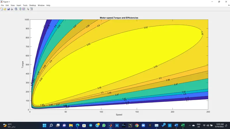
- Make a MATLAB program that plots the contour of given motor speed, torque, and efficiency values. Attach the code as a .m file and attach a screenshot of all the plots.
- %motor characteristics
- %speed_vs_torque_vs efficiency
- clc
- w = linspace(0,1000); %speed of the motor
- t= linspace(0,250); %torque
- %Motor Losses
- %for copper loss
- k_c = 0.2;
- %for iron loss
- k_i = 0.008;
- %for winding loss
- k_w = 0.00001;
- % constant loss
- cl = 20;
- % Making 2d matrix
- [W,T] = meshgrid(w,t);
- % Output power = torque*Speed
- Out_power = (T.*W);
- % Copper Loss
- b = (T.^2)*k_c;
- % Winding Loss
- c = (W.^3)*k_w;
- % Iron Loss
- d = W*k_i;
- % Input Power
- In_power = Out_power +b +c +d +cl;
- % Efficiency
- E= Out_power./In_power;
- %Efiiciency levels for contour
- e=[0.70,0.75,0.80,0.82,0.87,0.89,0.90,0.92];
- %plotting the graph
- %Creating Contour
- [C,h]=contourf(T,W,E,e);
- clabel(C,h,'labelspacing',300); % plotting the effeciency values and its scpacing
- xlabel('Speed');
- ylabel('Torque');
- title('Motor speed,Torque and Efficiencies')
Explanation
The program starts with assigning Input of Speed and Torque in an array using 'linspace' Command and allocates Constant Values for four losses (Copper Loss, Iron Loss, Windage Loss, and Constant Motor Loss)
Mesh the Speed and Torque values using 'meshgrid' command. Basically, it makes the size of both arrays equal.
Calculate the Output Power by multiplying Speed and Torque values.
Calculate Copper Loss, Iron Loss, and Windage Loss using those formulas.
Calculating Input power by adding Output Power and Four Losses(Copper Loss, Iron Loss, Windage Loss and Constant Motor Loss).
The ratio of Output Power and Input Power we can get the Efficiency.
Now Set the Efficiencies for which a contour will be plotted. The range of contour efficiency is to plot Plot the Contour Efficiency using 'contour' command and plot Speed, Torque, Efficiency, and V.'contour(X,Y,Z)' specifies the x and y coordinates for the values in Z. Contourf(Z) creates a filled contour plot containing the isolines of matrix Z, where Z contains height values on the x-y plane.
clabel(C,h) labels the current contour plot with rotated text inserted into each contour line. The contour lines must be long enough to fit the label, otherwise clabel does not insert a label.
Now the below plot shows the Motor Speed-Torque Efficiency Contour Plot with increasing efficiency order as going inward and decreasing efficiency order as going outward