Week-11 Challenge: Braking
Question 1):- For a defined driving cycle, calculate the energy required for braking.
ANS:
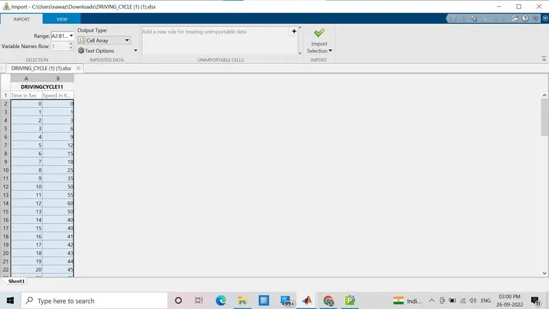
I make Xl_sheet data time and speed data make drive cycle as shown in the below image:

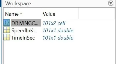
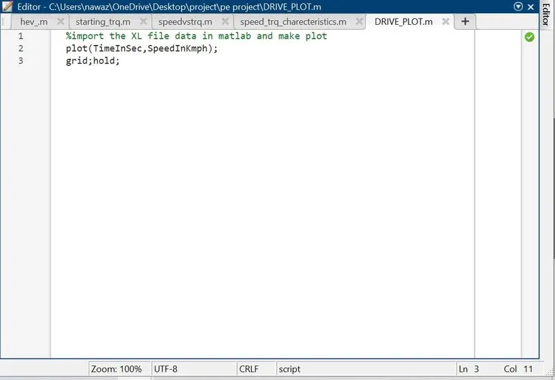
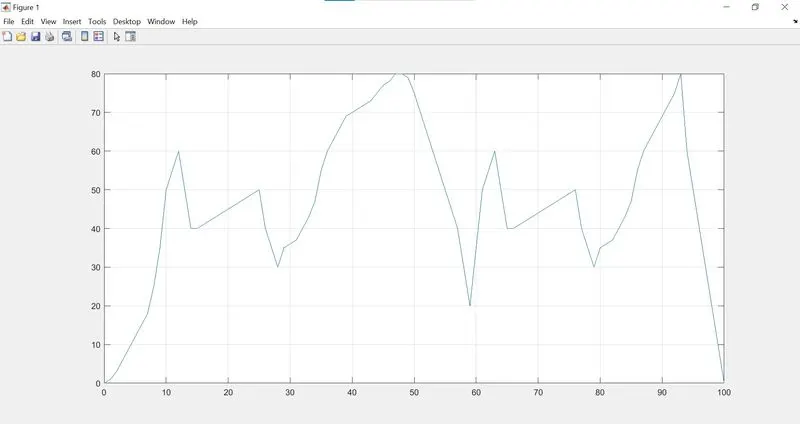
Import this sheet in Matlab after importing all data saved in the workspace then give the plot command through the script then the plot is created in Matlab.
Plot:
Calculation:-
|
Vehicle weight - 1000kg |
|||||||
| No. of Braking | Initial velocity (kmph) | Final velocity (kmph) | Time required (s) | Deceleration (m/s^2) | Energy required (J) | Braking power (W) | Braking energy (Wh) |
| 1 | 60 | 40 | 3 | 1.85 | 277778 | 92592.6 | 25.7 |
| 2 | 50 | 30 | 3 | 1.85 | 222222 | 74074.1 | 20.6 |
| 3 | 80 | 20 | 11 | 1.52 | 833333 | 75757.6 | 21.0 |
| 4 | 60 | 40 | 3 | 1.85 | 277778 | 92592.6 | 25.7 |
| 5 | 50 | 30 | 3 | 1.85 | 222222 | 74074.1 | 20.6 |
| 6 | 80 | 0 | 7 | 3.17 | 888889 | 126984.1 | 35.3 |
| Total braking energy required (Wh) | 148.9 | ||||||
Question 2):- Why electric motor can’t develop braking torque at a high speed similar to starting? How electric and mechanical brakes are coordinated?
ANS:
The electric motor can't develop braking torque at a high speed similar to starting because once the electric supply is pulled off from the motor, it acts as a generator and due to the flux weakening effect of the electric generator, the generator produces low torque as expected.
Regenerative Braking:
Regenerative braking is an energy recovery mechanism that slows down a moving vehicle or object by converting its kinetic energy into a form that can be either used immediately or stored until needed. In this mechanism, the electric traction motor uses the vehicle's momentum to recover energy that would otherwise be lost to the brake discs as heat. This contrasts with conventional braking systems, where the excess kinetic energy is converted to unwanted and wasted heat due to friction in the brakes, or with dynamic brakes, where the energy is recovered by using electric motors as generators but is immediately dissipated as heat in resistors. In addition to improving the overall efficiency of the vehicle, regeneration can significantly extend the life of the braking system as the mechanical parts will not wear out very quickly.
The most common form of regenerative brake involves an electric motor functioning as an electric generator. In electric railways, the electricity generated is fed back into the traction power supply. In battery electric and hybrid electric vehicles, the energy is stored chemically in a battery, electrically in a bank of capacitors, or mechanically in a rotating flywheel. Hydraulic hybrid vehicles use hydraulic motors to store energy in the form of compressed air. In a hydrogen fuel cell powered vehicle, the electrical energy generated by the motor is used to break waste water down into oxygen and hydrogen which is recycled back into the fuel cell for later reuse.
The most common form of regenerative brake involves using an electric motor as an electric generator. The working of the regenerative braking system depends upon the working principle of an electric motor, which is an important component of the system. The electric motor gets activated when some electric current is passed through it. But, when some external force is applied to activate the motor (during the braking), then it behaves as a generator and generates electricity. This means that whenever the motor runs in one direction, the electric energy gets converted into mechanical energy, which is then used to accelerate the vehicle, and whenever the motor runs in the opposite direction, it performs the functions of a generator, which then converts mechanical energy into electrical energy, which makes it possible to utilize the rotational force of the driving axle to turn the electric motors, which results in regenerating electric energy for storage in the battery and simultaneously reducing the speed of the car with the regenerative resistance of the electric motors. This electricity is then used for recharging the battery.
Coordination of Electric and Mechanical Brake :
In an electric motor, the Total Brake distribution is in two aspects the Electrical Brake which is called Regenerative Brake, and Mechanical Brake or Classical Brake with a hydraulic cylindrical system. Brake Force distribution must be uniform, If the Regenerative braking power requirement is more than the charging limit of the battery or more than the regenerative capacity of the machine we must apply Mechanical brakes as well. In a practical case, the combination of these two is applied. So usually it is a combined response of Mechanical brake and Regenerative brake. The reason for how this braking force is combined, is that particular phenomena are called Brake Control Strategies. There are two Brake Control Strategies, which are Series - In the case of Series, we apply Mechanical brake and Regenerative electric brake one after another. We can apply only one brake strategy at a time either apply Regeneratively or apa ply Mechanical brake. The Series Brake Control Strategy has a further classification, that is based on whether we want the comfort of driver or Brake behavior compared to energy efficiency. Parallel - In the case of Parallel, we apply both brakes simultaneously. This Particular Parallel braking is going to happen both at a time. Electric Driven Intelligent Brake (EDIB) is a combination of a Hydraulic brake or Mechanical brake along with a Regenerative brake. It is a Parallel braking technique. The Control criteria are such that at low speed use regenerative braking higher and at high speed or during the initial braking period we combine the.
Question 3):- Make a MATLAB program which plots contour of given motor speed, torque and efficiency values. Attach the code as a .m file attach a screenshot of all the plots?
ANS:
Code:
Plot:
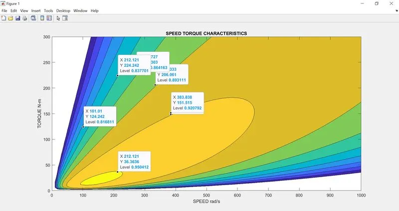
you could see that only at a particular speed and torque the efficiency is at maximum i.e. 95 %.
To plot contour line for a given Motor. A Motor has various types of losses happening inside. The various types of losses are:
Copper Losses - I^2R, where R is the Armature resistance and we say that Torque is proportional to Current, this copper loss can be considered as .where is to take care of resistance of brushes and also take care of us and its effect.
Copper losses = k_c*T^2
Iron Losses - Iron Losses are nothing but Magnetic losses, which are denoted as, where the factor is based on the Magnetic eld effect. Permanent Magnets have constant Magnetic eld and this Iron loss is based on the value of and this is going to change according to the Speed. Various Speeds have different values of Back EMF and that is going to affect the Iron Losses.
Iron Losses = k_i*omega
Windage Losses - This is a Mechanical or friction of Windage losses. This is based on the size of the shape of the Motor and the number of windage losses that the motor is going to experience.
Windage Losses = k_w*omega^3
Constant Losses - This is denoted as C.
Total Losses - The Total Losses are considering the above four losses and denoted as,
Total Losses = k_c*T^2 + k_i*omega + k_w*omega^3 + CAll Motors are modeled as per the above equation of losses this above equation is not only applicable for Permanent Magnet DC Motor but to their motors as well like inductimotorstor.