Project - Speed Control of a Direct Current (DC) motor
Aim:
In this project, a Simulink model for the DC motor will be first developed per the schematic.
Use the Proportional, Integral, and Derivative (PID) control design knowledge gained in the training to design, develop and test a controller to maintain a desired speed for the motor.
summary:
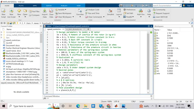
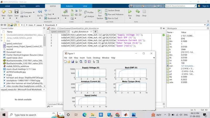
1). In this question first I made a script file for design & plot the graph and write the program then run the script and I received a plot.
2). I made the program in Simulink according to the PID controller to maintain the desired speed for the motor.
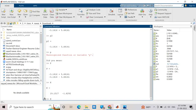
3). I made a program for P, I, and D gains and placed command of K then find the value of Kp, Kd.
4). In this question I used Step, Gain, Integrator, Workspace, Transfer function, Sum, Mux, and also Scope blocks.
5). I used supply voltage 230V.
6). I used imaginary value in Ki gains.
Matlab script to define modeling and control design parameters:
% Design parameters to model a DC motor
Jm = 0.01; % Moment of inertia of the rotor in kg-m^2
Bm = 0.1; % Motor viscous friction constant in N-m-s
Km = 0.01; % Back EMF constant in v/rad/s
Kt = 0.01; % Motor torque constant in N-m/amp
Ra = 0.5; % Resistance of the armature circuit in ohms
La = 0.25; % Inductance of the armature circuit in henries
% Nominal parameters of the spring-mass system
m = 100.0; % mass of the spring-mass system
k = 3944.0; % stiffness constant of the spring-mass system
% Equivalent wn
wn = 6.2832; % sqrt(k/m) rad/s
fn = 1.0; % wn/(2*pi) hz
% Design parameters
zeta = 0.5; % Under damped system design
% Desired poles
p1 = -zeta*wn+wn*sqrt(zeta^2-1);
p2 = -zeta*wn-wn*sqrt(zeta^2-1);
P = [p1;p2];
% A & B matrices
A = [-Bm/Jm Kt/Jm; -Km/La -Ra/La];
B = [0; 1/La];
% Pole placement design
K = place(A,B,P);
Plot commands:
subplot(321);plot(out.time,out.vs);grid;title('Supply Voltage (V)');
subplot(322);plot(out.time,out.vb);grid;title('Back EMF (V)');
subplot(323);plot(out.time,out.ia);grid;title('Armature Current (A)');
subplot(324);plot(out.time,out.t);grid;title('Motor Torque (N-m)');
subplot(325);plot(out.time,out.w);grid;title('Speed (rad/s)');
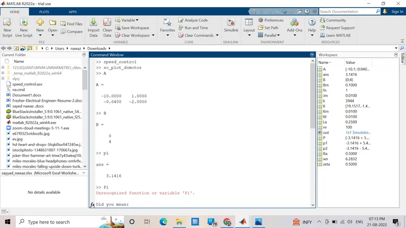
After running script command I check all values in the command window:
Simulink model to simulate and verify the design:
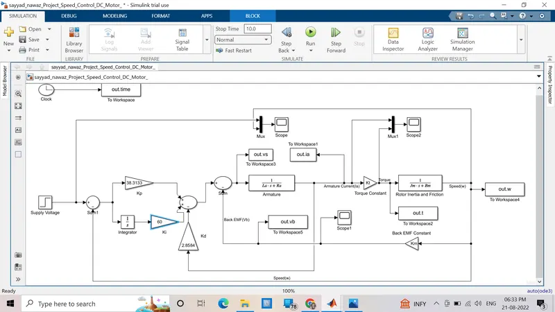
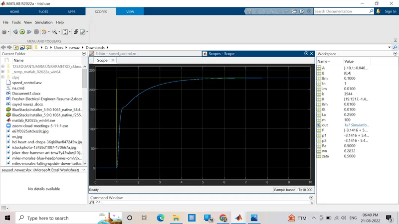
after running the simulation module I analyze the scope and graph data:
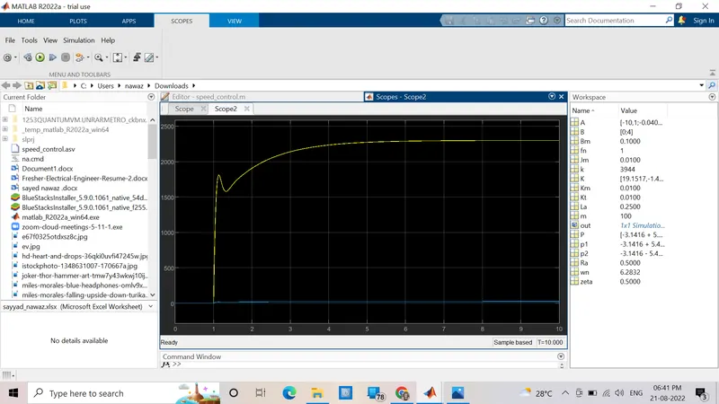
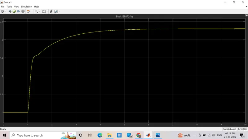
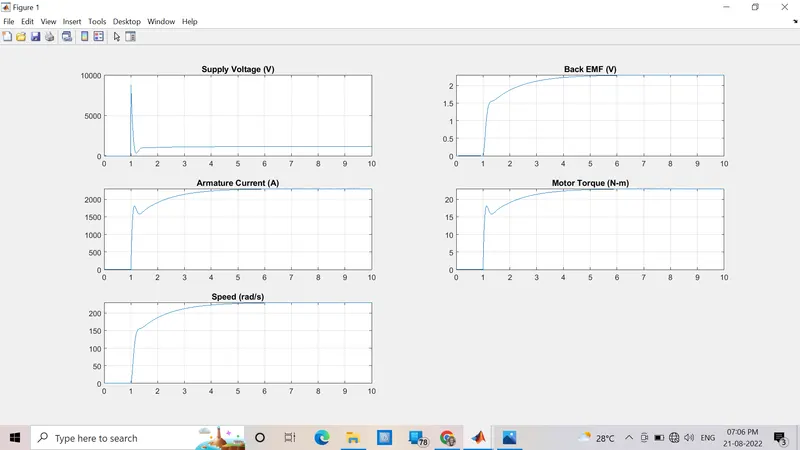
Conclusion: Dc motor control by using PID and motor run at armature control current.