Week-11 Challenge: Braking
1. For a defined driving cycle, Calculate the energy required for braking.
2. Why electric motors can't develop braking torque at a high speed similar to starting? how electric and mechanical brakes are coordinated?
3. Make a MATLAB program that plots the contour of given motor speed, torque, and efficiency values. Attach the code A.m file and attach a screenshot of all plots.
1. For a defined driving cycle, Calculate the energy required for braking.
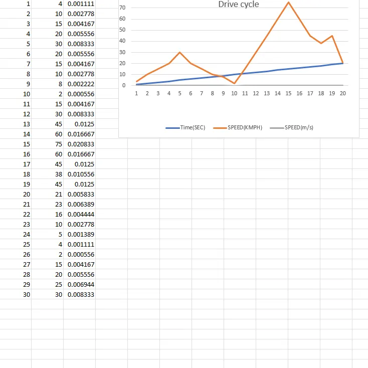
Drive cycle to be defined Randomly,
Here,
m=1000, ----- Mass of the vehicle,
We considered for the first 10 seconds,
achieving top speed while accelerating, V2 = 30kmph =8.333m/s
being low speed while deceleration, V1 = 2kmph = 5.566m/s
The energy required for braking :
For the first 10 seconds
BE1 =1/2 *m*(V2-V1)^2
BE1 = 0.5*1000*(8.333- 5.566)^2
BE1 = 500*(2.767)^2
BE1 = 500*(7.656)
BE1 = 382.8KW
For the next 20 seconds,
BE2 = 1/2 *m*(V2-V1)^2
BE2 = 0.5*1000*(4.167-2.083)^2
BE2 = 500 *(2.084)^2
BE2 = 500*4.34
BE2 = 217.8 KW
Total Energy required for braking,
BE total = BE1 + BE2
BE total = 382.8+217.8
BE total = 600KW
From the above solution we obtained, the energy required for braking is 600KW.
2. Why electric motor cant develop braking torque at a high speed similar to starting? How electric and mechanical brakes are coordinated?
Electric Motor:
An electric motor is used to convert electrical energy into mechanical energy. Most electric motors operate through the interaction between the motor's magnetic field and electric current in a wire winding to generate force in the form of torque applied on the motor's shaft.
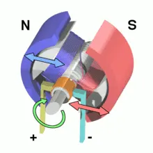
This image shows a brushed DC electric motor.
The electric motor can develop braking torque at a high speed similar to starting:
The electric motor can't develop braking torque at a high speed similar to starting. Because the braking motor runs at regenerative braking. Similarly, the torque in the brake will be small. While the increase in braking torque, the speed of the motor decreases. If the motor runs in opposite or negative, The motor is at in both regenerative braking as well as mechanical braking
How Electric and Mechanical brakes are coordinated:
Electrical Braking:
In many applications, it is necessary to stop the motor quickly and start quickly. Delay in starting a motor keeps machinery idle causing no adverse effects. But a delay in stopping a motor can cause heavy damage to equipment. Hence electric braking is important which stops the electric machines more quickly than mechanical brakes. In electric braking, the stored energy in the rotating parts of an electric machine is converted into electric energy and dissipated by the resistance in the form of heat or returned to the supply.
Types of electric braking:
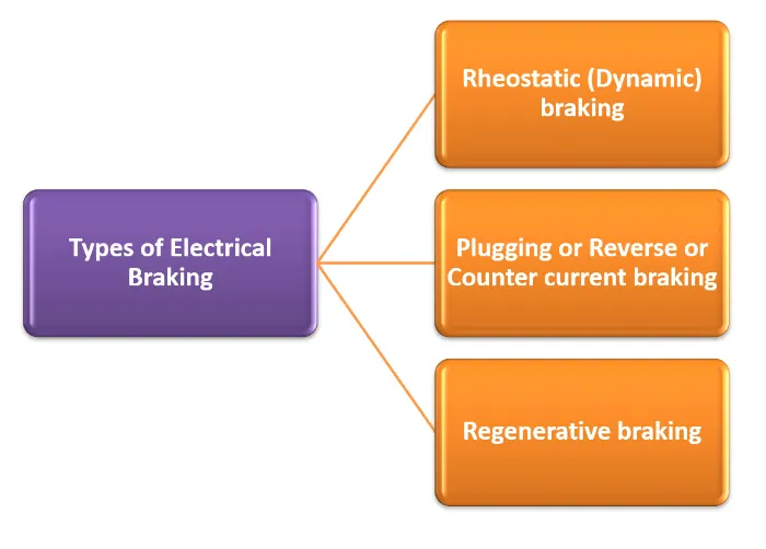
Rheostatic (Dynamic) braking:
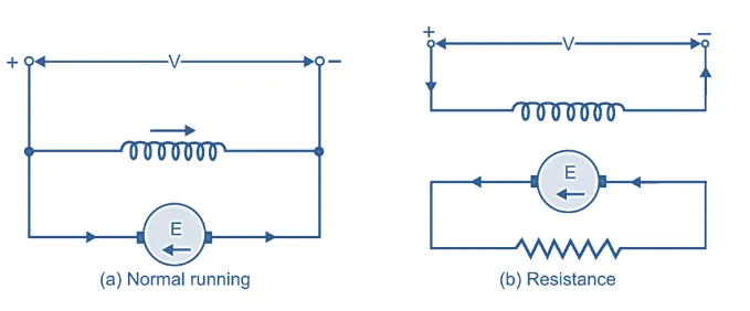
In this method, mechanical energy is converted to electrical energy and dissipated in the resistance as heat which acts as an electrical load.
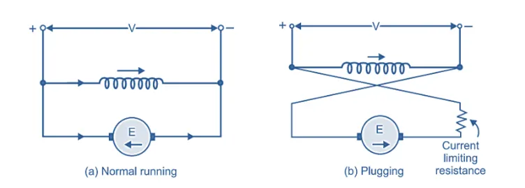
Plugging or Reverse or Counter Clock Braking:
In this method, the power supply connections of the motor are reversed. So that it tends to drive the motor in opposite direction and eventually comes to rest where supply is cut off.
Regenerative Braking:
Among these braking, Regenerative braking is the most prominent method. In this method, the motor is operated as a generator and still connected to the supply. The mechanical energy, converted to electrical is returned to the supply.
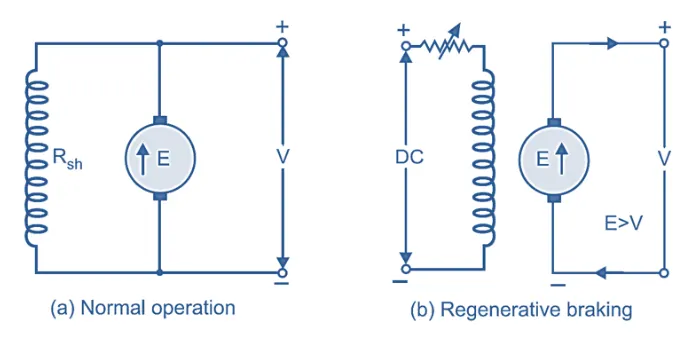
In the above-mentioned figures, A represents Normal operation & B represents Braking operation.
Advantages of Electrical Braking:
- It is economical and very fast.
- No need for any mechanical equipment.
- very little maintenance is required.
- Operation is clean and dust free.
- The energy is converted to electrical and fed back to the supply network.
- The braking is very smooth without steps.
- It is easier, economically effective, and efficient.
- The automatic control is possible using a closed loop.
Disadvantages Of Electrical braking:
Holding torque can not be produced. It can not hold the motor at any desired position.
The choice of motor is limited as it must have suitable braking characteristics.
The safety considerations are to be properly monitored and observed.
The power consumption is more
Mechanical braking:
Mechanical braking is an important control system in vehicles This braking is a combination of some interactive parts. It absorbs energy from the moving part and slows down the vehicle with help of the friction.
Types of Mechanical Braking
Disc braking
Hydraulic braking
Disc brake:
When the pedal is pressed piston pushes the pad by the pressure of the hydraulic fluid. These Friction pads rub against the rotating disc connected to the wheels of the vehicle and thus braking takes place. When the pedal is released friction pad returns to its original position as the pressure of hydraulic fluid reduces.
Hydraulic braking:
Hydraulic braking works on the principle which is based on pascal's principle, which states that "confined liquid transmits pressure without loss in all direction".
Coordination Of electrical and Mechanical braking:
In the electric motor, the braking consists of two types, Which are Electrical brakes(Regenerative braking) and another brake is mechanical braking (Normal braking or Hydraulic braking).
Brake control strategies are the method by which the combination of mechanical and electrical brakes is done.
Single braking method :
The mechanical and electrical brakes are done one after another. By using the control strategy we can use either mechanical or electrical.
Multi Braking method:
In this method, we can use both the Brakes at the same time.
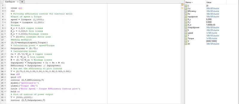
3. Make a MatLab program that plots the contour of given motor speed, torque, and efficiency values. Attach the coed as an a.m file and attach a screenshot of the plots.
Matlab code:
clear all
clc
% plotting efficiency contour for electric motor
%Input of speed &Torque
%Losses
K_c = 0.2; % copper losses
K_i = 0.008; %Iron losses
K_w = 0.00001; %Windage losses
C = 20; %For constant motor losses
%Making meshgrid
[S,T] = meshgrid (speed,Torque)
% Calculating power = speed * Torque
Outputpower = (S.*T);
%Calculating Losses
Cu = (T.^2)*K_c; %copper losses
Fe = S * K_i;%Iron losses
W = (S.^3)*K_w; %windage losses
Inputpower = Outputpower + Cu + Fe + W + c ;
Efficiency = Outputpower ./ Inputpower;
% Now set the efficiency to plot Contour
V = [0.70,0.80,0.85,0.90,0.91,0.92,0.925,0.93];
box off
grid off
contour (S,T,Efficiency,V)
Xlabel ('Speed(rad/s)')
ylabel ('Torque(Nm)')
title ('Motor speed - Torque efficiency Contour plot')
hold on
% Plot of contour of power output
V = [8000,10000];
contour (S,T,Outputpower,V)
%plotting
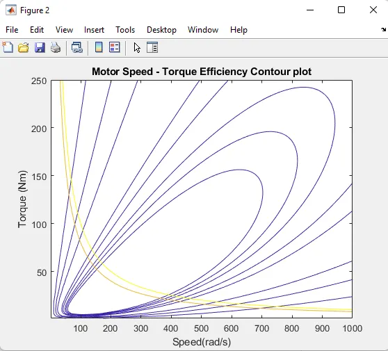
The above plots represent the motor speed-Torque Efficiency Contour plots. In this graph is represents the high efficiency as apporoximately 90% above.And lowset efficiency of the graph is approximately 70%