Week-11 Challenge: Braking
- For a defined driving cycle, calculate the energy required for braking.
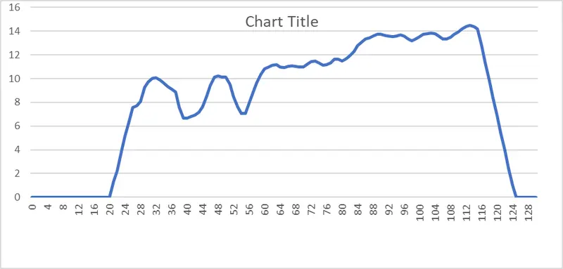
The driving cycle taken into consideration is the USSD cycle which stands which stands for urban Dynamometer driving schedule although the Data is taken for a total
Driving time for 1370, for simplicity’s sake an 150s driving time is considered
The speed which is in miles per hour has been converted to meter per second
|
UDDS CYCLE |
|
|
Time in s |
Speed in m/s |
|
0 |
0 |
|
1 |
0 |
|
2 |
0 |
|
3 |
0 |
|
4 |
0 |
|
5 |
0 |
|
6 |
0 |
|
7 |
0 |
|
8 |
0 |
|
9 |
0 |
|
10 |
0 |
|
11 |
0 |
|
12 |
0 |
|
13 |
0 |
|
14 |
0 |
|
15 |
0 |
|
16 |
0 |
|
17 |
0 |
|
18 |
0 |
|
19 |
0 |
|
20 |
0 |
|
21 |
1.34 |
|
22 |
2.23 |
|
23 |
3.84 |
|
24 |
5.14 |
|
25 |
6.43 |
|
26 |
7.55 |
|
27 |
7.73 |
|
28 |
8.09 |
|
29 |
9.25 |
|
30 |
9.7 |
|
31 |
10.01 |
|
32 |
10.05 |
|
33 |
9.87 |
|
34 |
9.61 |
|
35 |
9.34 |
|
36 |
9.11 |
|
37 |
8.85 |
|
38 |
7.59 |
|
39 |
6.66 |
|
40 |
6.66 |
|
41 |
6.79 |
|
42 |
6.92 |
|
43 |
7.15 |
|
44 |
7.64 |
|
45 |
8.53 |
|
46 |
9.43 |
|
47 |
10.14 |
|
48 |
10.23 |
|
49 |
10.14 |
|
50 |
10.1 |
|
51 |
9.52 |
|
52 |
8.49 |
|
53 |
7.64 |
|
54 |
7.06 |
|
55 |
7.06 |
|
56 |
7.91 |
|
57 |
8.85 |
|
58 |
9.65 |
|
59 |
10.37 |
|
60 |
10.81 |
|
61 |
11 |
|
62 |
11.13 |
|
63 |
11.17 |
|
64 |
11 |
|
65 |
10.95 |
|
66 |
11.04 |
|
67 |
11.08 |
|
68 |
11.04 |
|
69 |
11 |
|
70 |
11 |
|
71 |
11.22 |
|
72 |
11.44 |
|
73 |
11.48 |
|
74 |
11.35 |
|
75 |
11.13 |
|
76 |
11.17 |
|
77 |
11.35 |
|
78 |
11.62 |
|
79 |
11.62 |
|
80 |
11.48 |
|
81 |
11.66 |
|
82 |
11.93 |
|
83 |
12.29 |
|
84 |
12.78 |
|
85 |
13.1 |
|
86 |
13.32 |
|
87 |
13.45 |
|
88 |
13.6 |
|
89 |
13.72 |
|
90 |
13.72 |
|
91 |
13.63 |
|
92 |
13.6 |
|
93 |
13.54 |
|
94 |
13.6 |
|
95 |
13.7 |
|
96 |
13.6 |
|
97 |
13.36 |
|
98 |
13.18 |
|
99 |
13.32 |
|
100 |
13.54 |
|
101 |
13.72 |
|
102 |
13.81 |
|
103 |
13.85 |
|
104 |
13.81 |
|
105 |
13.6 |
|
106 |
13.32 |
|
107 |
13.36 |
|
108 |
13.5 |
|
109 |
13.72 |
|
110 |
13.94 |
|
111 |
14.21 |
|
112 |
14.4 |
|
113 |
14.48 |
|
114 |
14.4 |
|
115 |
14.17 |
|
116 |
12.78 |
|
117 |
11.31 |
|
118 |
9.83 |
|
119 |
8.35 |
|
120 |
6.88 |
|
121 |
5.4 |
|
122 |
3.93 |
|
123 |
2.45 |
|
124 |
0.98 |
|
125 |
0 |
|
126 |
0 |
|
127 |
0 |
|
128 |
0 |
|
129 |
0 |
|
130 |
0 |
The equation for kinetic energy from braking is given is given as
E=1/2 m(vi-vf)2
m=mass of the vehicle kg
vi= initial speed of the vehicle in m/s
vf= final speed of the vehicle in m/s
|
ENERGY FROM BRAKING |
||||
|
Initial Speed (Vi) in m/s |
Final Speed (Vf) in m/s |
Mass in Kg |
Braking Energy |
|
|
8.85 |
6.65 |
1500 |
3630 |
|
|
10.1 |
7 |
1500 |
7207.5 |
|
|
11.17 |
10.95 |
1500 |
36.3 |
|
|
11.08 |
11 |
1500 |
4.8 |
|
|
11.48 |
11.13 |
1500 |
91.875 |
|
|
11.62 |
11.48 |
1500 |
14.7 |
|
|
13.72 |
13.54 |
1500 |
24.3 |
|
|
13.7 |
13.18 |
1500 |
202.8 |
|
|
13.85 |
13.32 |
1500 |
210.675 |
|
|
14.48 |
0 |
1500 |
157252.8 |
|
|
Total Energy |
168675.75 |
|||
The equation for kinetic energy from braking is given is given as
E=1/2 m(vi-vf)2
m=mass of the vehicle kg
vi= initial speed of the vehicle in m/s
vf= final speed of the vehicle in m/s
|
ENERGY FROM BRAKING |
||||
|
Initial Speed (Vi) in m/s |
Final Speed (Vf) in m/s |
Mass in Kg |
Braking Energy |
|
|
8.85 |
6.65 |
1500 |
3630 |
|
|
10.1 |
7 |
1500 |
7207.5 |
|
|
11.17 |
10.95 |
1500 |
36.3 |
|
|
11.08 |
11 |
1500 |
4.8 |
|
|
11.48 |
11.13 |
1500 |
91.875 |
|
|
11.62 |
11.48 |
1500 |
14.7 |
|
|
13.72 |
13.54 |
1500 |
24.3 |
|
|
13.7 |
13.18 |
1500 |
202.8 |
|
|
13.85 |
13.32 |
1500 |
210.675 |
|
|
14.48 |
0 |
1500 |
157252.8 |
|
|
Total Energy |
168675.75 |
|||
Therefore total energy required for braking is 16.8 kw
2.Why electric motor can’t develop braking torque at high speed similar to starting? How electric and mechanical brakes are coordinated?
How electric and mechanical brakes are coordinated?
Coordination of Electric with Other Braking Systems
HOW electric-actuated trailer brakes synchronized with the air, hydraulic, or vacuum are braking system as used on tractors is described here.
Brake balance between the electric and other systems used involves balance of brake buildup rime. This is done by having the two types of brakes build up simultaneously for their respective axle loads and tire sizes. A load control consisting of a variable rheostat does this job for the electric brakes. It is also used for balancing the electric brakes with the tractor brake system.
The speed and versatility of electricity as used for trailer brakes make possible synchronized braking of combination vehicles without sacrifice of tractor brake speed — all brakes work simultaneously, resulting in shorter stops and less danger of jaakknifing.
Other important safety features of the electric brake include: (1) They furnish an independent braking system for the trailer. (2) They are operated by a constant source of power
According to whether or not the hydraulic braking system is involved in braking, the braking mode-switch type is divided into two categories (Figure 6). Braking mode-switch coordination control strategies are developed for the different braking mode-switch types.
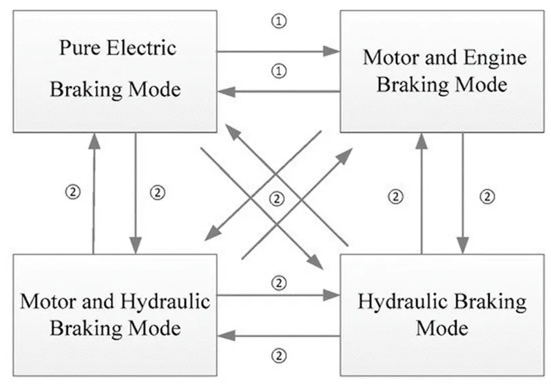
(1) Type one: braking mode switch without hydraulic braking system participation. In this type of mode switching it is necessary to control the engagement of the clutch and the change rate of the motor torque. Thus, the fluctuation caused by mode switch can be reduced.
(2) Type two: braking mode switch with hydraulic braking system participation. Due to the different dynamic response characteristics of the motor and the hydraulic braking systems, this switch mode is difficult to coordinate. The idea of coordinating control is to take full advantage of the characteristics of the braking systems. The hydraulic system can provide large and stable torque, and the motor braking system’s torque response is quick and accurate, reducing the fluctuation of the vehicle.
1. Kinetics Analysis of Braking Mode
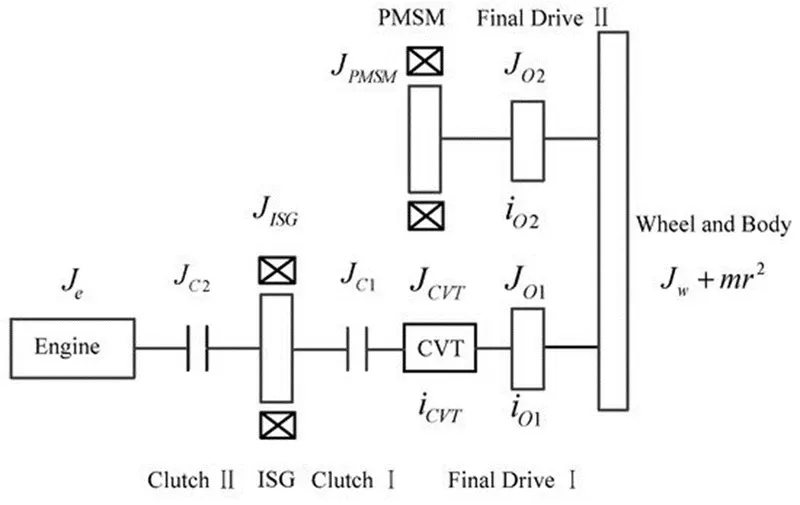
According to the braking force distribution control strategy mentioned above, there are four main braking modes: pure electric braking mode, motor and engine braking mode, motor and hydraulic braking mode, and hydraulic braking mode. In order to facilitate the kinetic analysis, the hybrid vehicle drive system model is simplified, as illustrated in Figure 5. where Je is moment of inertia of the engine; JISG is moment of inertia of the ISG; Jcvt is moment of inertia of the CVT; JC1 is moment of inertia of the clutch I; JC2 is moment of inertia of the clutch II; JPMSM is moment of inertia of the PMSM; Jw is moment of inertia of the wheel; JO1 is moment of inertia of the final drive I; JO2 is moment of inertia of the final drive II; m is the vehicle mass; r is the tire radius.
(1) Pure Electric Braking Mode
When the motor is braking clutch I is engaged and clutch II is disconnected. The engine and the hydraulic braking systems do not participate in the braking action and the required braking torque is provided by the motor. The equivalent to the moment of inertia on the wheel is:
Jv=((JISG+JC1)⋅icvt+JCVT)⋅iO1+JO1+JO2+JPMSM⋅iO2+Jw+mr2
(14)
The dynamic equation of braking is:
⎧⎩⎨⎪⎪TbICE=0Tbh=0TbISG⋅icvt⋅iO1+TbPMSM⋅iO2=Jvωw∙
(15)
where TbICE is the engine drag resistance torque, Tbh is the hydraulic braking torque, TbISG is the ISG braking torque, TbPMSM is the PMSM braking torque, and ω˙w is the wheel angular acceleration.
(2) Motor and Engine Braking Mode
When the motor and engine are involved in braking, clutches I and II are engaged. The required braking torque is provided by the motor and the engine. At this time, the equivalent to the moment of inertia on the wheel is:
Jv=((Je+JISG+JC1+JC2)⋅icvt+JCVT)⋅iO1+JO1+JO2+JPMSM⋅iO2+Jw+mr2
(16)
The dynamic equation of braking is:
{Tbh=0(TbISG+TbICE)⋅icvt⋅iO1+TbPMSM⋅iO2=Jvωw∙
(17)
(3) Motor and Hydraulic Braking Mode
During motor and hydraulic braking modes, clutch I is engaged and clutch II is disconnected. The required braking torque is provided by the motor and the hydraulic braking system. At this time, the equivalent to the moment of inertia on the wheel is:
Jv=((JISG+JC2)⋅icvt+JCVT)⋅iO1+JO1+JO2+JPMSM⋅iO2+Jw+mr2
(18)
The dynamic equation of braking is:
{TbICE=0TbISG⋅icvt⋅iO1+TbPMSM⋅iO2+Tbh=Jvωw∙
(19)
(4) Hydraulic Braking Mode
During hydraulic braking mode, clutches I and II are disengaged and the required braking torque is provided by the hydraulic braking system. The equivalent to the moment of inertia on the wheel is:
Jv=JCVT⋅iO1+JO1+JO2+JPMSM⋅iO2+Jw+mr2
(20)
The dynamic equation of braking is:
⎧⎩⎨⎪⎪TbICE=0TbISG=TbPMSM=0Tbh=Jvωw∙
(21)
Based on the kinetics analysis of the braking mode, there are three types of braking torque that need to be coordinated during braking mode switching. The motor, the hydraulic, and the engine braking systems are three different systems with different dynamic response characteristics; therefore, the sequences and moments of the three joint systems are different. Because mode switching is completed instantaneously, the braking torque varies sharply during the intervention and exit from braking. If there is no coordinated control, it will cause torque fluctuation and seriously worsen the ride comfort of the vehicle.
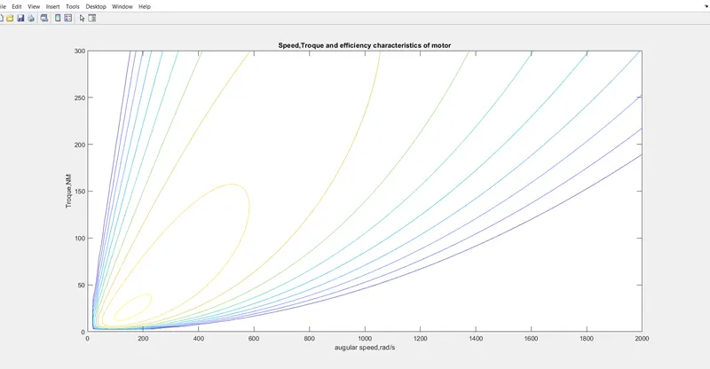
- 3. Make a MATLAB program which plots contour of given motor speed, torque and efficiency values. Attach the code as a .m file attach a screenshot of all the plots.
close all;
clc;
omge=linspace(0,300,100); %speed array
T=linspace(0,2000,100); %Troque array
[X,Y]=meshgrid(T,omge); %meshgrid
cu=0.17;%copper cofficient
fe=0.06; %iron cofficient
win=0.000015;%windage cofficient
cu_loss=cu*(Y.^2); %copper loss
fe_loss=fe*X; %iron cofficient
win_loss=win*(X.^3); %windage loss
cond_loss=18; %conduction loss
p_out=(X.*Y); %output power
p_in=p_out+(cu_loss)+(fe_loss)+(win_loss)+(cond_loss); %input power
n=((p_out)./(p_in)); % efficiency
W=linspace(0.75,0.95,10); % efficiency value contour
contour(X,Y,n,W)
xlabel('augular speed,rad/s')
ylabel('Troque,NM')
title('Speed,Troque and efficiency characteristics of motor')