Week-11 Challenge: Braking
Braking (Week 11):
Objective:
- For a defined driving cycle, calculate the energy required for braking.
- Why electric motor can’t develop braking torque at high speed similar to starting? How electric and mechanical brakes are coordinated?
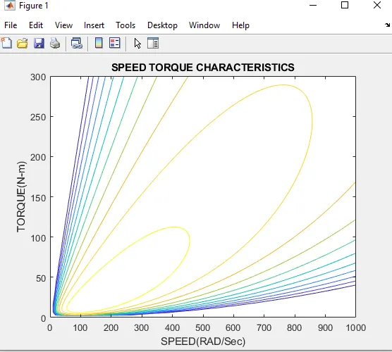
- Make a MATLAB program which plots contour of given motor speed, torque and efficiency values. Attach the code as a .m file attach a screenshot of all the plots.
#Study 1: For a defined driving cycle, calculate the energy required for braking.
Abstract
In Hybrid Electric Vehicles, Regenerative Braking is an essential function to convert vehicle kinetic energy into electrical energy, which charges the battery during a braking event to make a portion of captured kinetic energy available for use later. In comparison, conventional vehicles use friction brakes only and kinetic energy is dissipated as heat and not made available for later use. This paper introduces methods of evaluating Regenerative Braking Efficiency, including multiple efficiency definitions that lead to different attributes. The paper proposes regenerative brake event definitions during the FTP cycle and how they are used for control strategy and calibration updates. Also, we apply the efficiency metrics to four different vehicles from four automotive manufacturers for comparison. The paper presents a sample comparison result. Finally, we compare our efficiency metrics with the Environmental Protection Agency (U.S.EPA) official Brake Energy Recovery efficiency evaluation process.
Braking energy BE = ½ mv^2
m = mass of vehicle
v = speed of vehicle
Drive cycle:
A driving cycle commonly represents a set of vehicle speed points versus time. It is used to assess fuel consumption and pollutants emissions of a vehicle in a normalized way, so that different vehicles can be compared. The driving cycle is performed on a chassis dynamometer, where tailpipes emissions of the vehicle are collected and analyzed to assess the emissions rates.
In commercial vehicles area, the driving cycle is not performed on a vehicle dynamometer but on an engine dynamometer and is evaluated through a set of engine torque and speed points instead of vehicle speed points.
There are two kinds of driving cycles, the modal cycles as the European standard NEDC, or Japanese 10-15 Mode and the transient cycles as the FTP-75 or Artemis cycle. Main difference is that modal cycles are a compilation of straight acceleration and constant speed periods and are not representative of a real driver behavior, whereas transient cycles involve many speed variations, typical of on-road driving conditions.
Importance of Drive cycle:
Main uses of driving cycles are
- To assess the performance of a vehicle (fuel economy, emission tests)
- To analyze battery state and energy consumption in Electric Vehicles
- To simulate vehicle model prior to the actual development
Transient Driving Cycle:
The transient driving cycle represents an actual pattern of a vehicle which contains acceleration, deceleration, constant speed, etc. Federal Test Procedure (FTP 75) is an example of a Transient Driving Cycle.
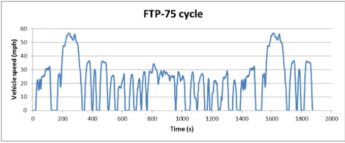
Total distance : 17.77 km
Total time : 1874 s
Average speed : 34.1 kmph
Vehicle mass = 1000 kg
BE = ½ * 1000*34.1
=17.5 kj
Braking energy calculation using Matlab:
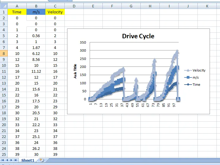
First create won drive cycle file then import xls file in matlab workspace window. Shown in below figure-
https://docs.google.com/spreadsheets/d/1_HJu6dz7HCdDtRabbbX5RvFCGQDE-JOX/edit?usp=sharing&ouid=112786727310165782214&rtpof=true&sd=true
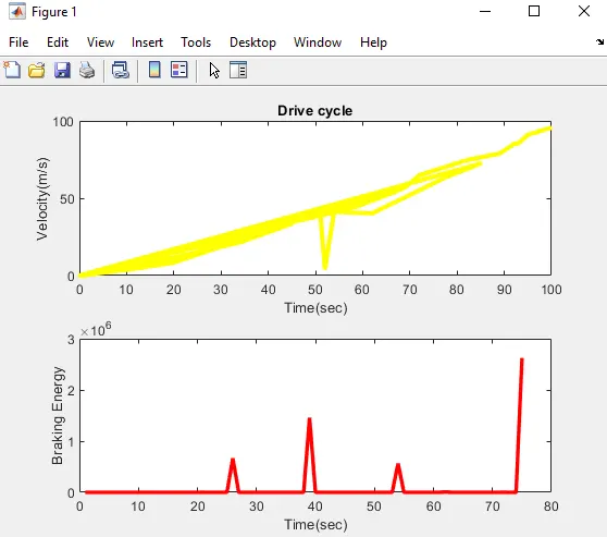
Matlab program of braking energy calculation:
%calculate the energy required for braking
mass = 1000; % mass of the vehicle in kg
Time = NDS(:,1); % time period
v = NDS(:,2); % velocity data in m/s
for i = 1:(length(NDS)-1)
if v(i)>v(i+1)
BE(i) = 0.5*mass*(v(i) - v(i+1))^2; % BE stands for break energy
end
end
fprintf('Total break Energy is %d' ,sum(BE))
fprintf('Average Break Energy is %d' ,mean(BE))
%Plotting the results
figure(1)
subplot(2,1,1)
plot(Time,v, 'LineWidth',3,'Color','y')
xlabel('Time(sec)')
ylabel('Velocity(m/s)')
title('Drive cycle')
subplot(2,1,2)
plot(BE,'LineWidth',2.5,'Color','r')
xlabel('Time(sec)')
ylabel('Braking Energy')
Result:
#Study 2: Why electric motor can’t develop braking torque at high speed similar to starting? How electric and mechanical brakes are coordinated?
Abstract
- tyre were discussed and it was shown how the braking force generated at the tyre contact patch depends on the value of the slip ratio which varies from zero for a free rolling wheel to unity for a braked and fully locked wheel. In this section we are not so much concerned with the tyre, given that we would be using a tyre model interfaced with our full vehicle model to represent his behaviour. Rather we now address the modelling of the mechanisms used to apply a braking torqueacting about the spin axis of the road wheel that produces the change in slip ratio and subsequent braking force.
- Clearly as the vehicle brakes, as shown in Figure 6.26, there is weight transfer from the rear to the front of the vehicle. Given what we know about the tyre behaviour the change in the vertical loads acting through the tyres will influence the braking forces generated. As such the braking model may need to account for real effects such as proportioning the braking pressures to the front and rear wheels or the implementation of ABS. Before any consideration of this we need to address the mechanism to model a braking torque acting on a single road wheel.
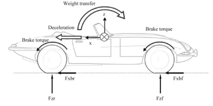
Electric motor can’t develop braking torque at high speed similar to starting:-
DC Motor Electric Brakes a braking torque which opposes the motion of the rotating member is developed during the braking operation. This is achieved by suitably changing the electrical connections of the motor. The motor operates on a speed-torque characteristic depending upon the method of braking employed. Whether mechanical or electrical, the braking of the drive should be such as to stop the motor at the specified point of time and location, for reasons of safety.
DC Motor Electric Brakes is of two kinds, depending upon the application of the drive:
- To bring the driving motor completely to rest in a given amount of time and at exactly specified points. While doing so, the K.E. is fed back to the mains.
- To restrict the speed to safe values. This arises normally while lowering loads using a hoist or crane. While maintaining constant speed the excess of K.E. and P.E. of the load tending to accelerate the motor is fed back to the mains.
Electric braking may be accomplished in any of the following three ways:
- Regenerative braking
- Dynamic or rheostatic braking
- Counter current braking.
- We have seen that DC Motor Electric Brakes makes it possible to convert the K.E. of the rotating parts to electrical energy. This energy can be returned to the mains or dissipated in an external resistance. The braking is called regenerative when the energy is returned to the mains. It is called dynamic or rheostatic braking when the energy is dissipated in a resistance. In either case the machine operates as a generator. Electric machinesare capable of smooth transition from motor to generator action.
- The load forces the motor in some applications to accelerate beyond no-load speed. The induced voltage becomes greater than the supply voltage to which the motor is connected and the current flows from the machine to the supply. It develops a torque to oppose the motion and hence to control the acceleration. The KE. and P.E., minus the losses of the motor, are returned to the mains and the motor runs at constant speed. Thus, regenerative braking eliminates any tendency of the load to accelerate the motor.
- Regenerative braking is also possible if the terminal voltage can be instantly decreased. The machine can be braked to zero speed. Reconnection of the motor is not necessary for regeneration. On the other hand, in dynamic braking the motor must be switched to the load resistancekeeping the field constant.
- Counter current braking is accomplished by reconnecting the supply to the armature of the motor so that the motor draws a current to develop a torque to oppose its already existing rotation. The motor acts as a brake and comes to rest very fast but has a tendency to accelerate in the reverse direction. If reversal is not required the supply to the motor must be cut off at zero speed. In the case of dc motors this is achieved by reversing the polarity of the supply voltage to the armature, while for ac motors the phase sequence is altered. The method is inefficient because of power loss in the resistors used for limiting the current, due to interconnection. The mechanical energyis converted to heat; there is additional power input from the supply. This method of braking is also employed to maintain a constant speed when the load tries to accelerate the rotor to high speeds, e.g. in the case of induction motors a suitable resistance of the rotor shifts the point of operation to the fourth quadrant.
How electric and mechanical brakes are coordinated:-
Regenerative braking can recover and reuse braking energy, which is an important characteristic of electric vehicles (EV). But it also has a negative impact on the control of anti-lock braking system(ABS). For the purpose of recovering energy efficiently, the constraints of braking force distribution between front and rear axle was analyzed, and then a regenerative braking distribution strategy was determined. The anti-lock control of the mechanical braking system was analyzed based on logic threshold method. To reduce the influence on ABS, the motor regenerative braking force was controlled to decrease rapidly as soon as ABS started. The simulation results show that the braking force control strategy used in this paper can recover energy adequately, ABS can work properly and coordinate with regenerative braking system when emergency braking.
Nissan has announced two innovative technologies for its upcoming Hybrid Nissan Fuga. We have already covered the first one – Electro Hydraulic Power Steering System. In this post I will share the second equally interesting innovation called the Electric Driven Intelligent Brake System.
- Most of the power brake systems derive vacuum from the engine intake manifold and use this energy to apply brake force which greatly reduces driver’s pedal force and brakes become highly responsive and easy to operate. One major disadvantage of this system is that it puts load on the engine since the braking energy is extracted from the engine. Also the energy lost in stopping the car almost all goes waste in conventional braking systems.
- In the Electric Driven Intelligent Braking System, the braking force is provided with the help of a ECU controlled motor and ball screw arrangement. This means that no direct load on the engine while applying brakes. This means that a motor operated the brake for providing the braking energy. A more controlled and uniform braking force is applied since its ECU controlled, this helps to recover braking losses when a regenerative braking systemis used.
#Study 3: Make a MATLAB program which plots contour of given motor speed, torque and efficiency values. Attach the code as a .m file attach a screenshot of all the plots.
Matlab script file:
clear
clc
% SPEED ARRAY
w = linspace(0,1000);
%TORQUE ARRAY
T = linspace(0,300);
% LOSS COEFFICIENTS
kc = 0.18; % COPPER LOSSES
ki = 0.006; % IRON LOSSES
kw = 0.000017; %WINDAGE LOSSES
% MESHGRID
[X,Y] = meshgrid(w,T)
copper_loss = (Y.^2)*kc
iron_loss = X*ki
windage_loss = (X.^3)*kw
cons = 20
o_p = X.*Y
input_power = (copper_loss)+(iron_loss)+(windage_loss)+(o_p)+cons
Eff = (o_p)./(input_power)
n = linspace(0.7,0.93,11)
box off
grid off
contour(X,Y,Eff,n)
title('SPEED TORQUE CHARACTERISTICS')
xlabel('SPEED(RAD/Sec)')
ylabel('TORQUE(N-m)')
Contour Plot: