Week-11 Challenge: Braking
Student of EV LIVE BATVH 16
Solution for Question 1:
CODE
m=1000;
%xlsread (drivecycle.xlsx);
t=drivecycle(:,1);
v=drivecycle(:,3);
for i=1:(length(drivecycle)-1);
if v(i)>v(i+1)
BE(i)=0.5*m*(v(i)-v(i+1))^2;
end
end
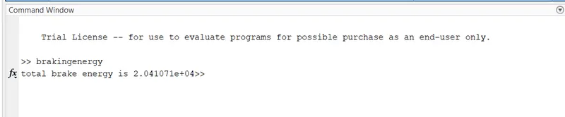
fprintf('total brake energy is %d', sum(BE))
%figure (1);
%plot (2,1,1);
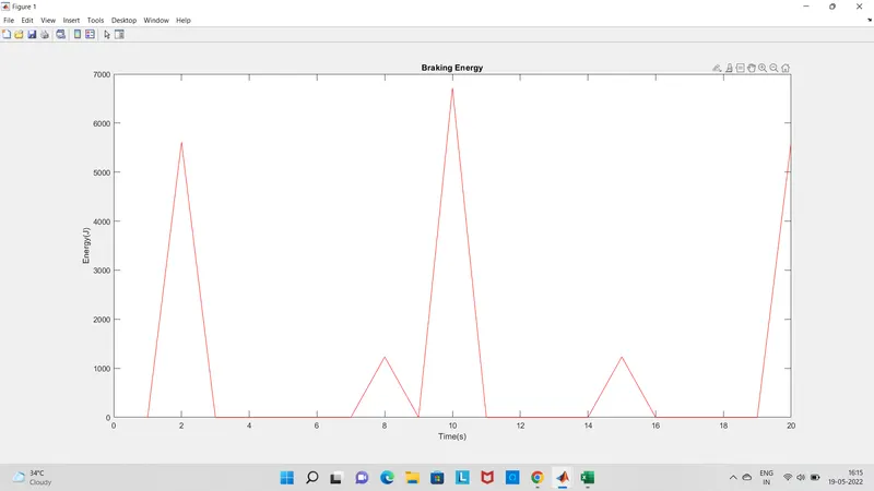
plot (BE,'color','r');
xlabel( 'Time(s)');
ylabel('Energy(J)');
title('Braking Energy')
RESULT:
PLOT :
Solution for Question 2:
Reason why electric motor can't develop braking torque at high speed similar to starting
- We know that torque of the induction motor is inverse proportional to the rotor speed.So that at higher speed the torque will be less.That's why at high speed electric motor can not produce braking torque similar to starting.
- If the mechanical load on the shaft increase the motor speed will decrease until the motor toque is again equal to the load torque.
Electric and Mechanical brakes coordination:
- In Electric vehicle, Motor must be controlled for proper amount of Braking force to recover as much braking energy as possible.
- The total braking force should be sufficient to meet vehicle deceleration commanded by the driver.
- To acheive such braking in the electric vehicle there are some braking strategies.
- Series braking control: In this, Mechanical and electric braking is done one after another.
- Parallel braking control: In this case, Both brakes applied simultaneosuly.
- we need both mechanical and electrical braking system.
- Mechanical brake: It is nothing but friction brakes used in vehicle to slow down the vehicle. Drum brakes and disc brakes are popular in this category.
- Electrical brake: we are reducing the speed of the motor depending on the flux and torque.
- Plugging, Dyanmic and regenerative braking are the types of electric braking
Solution for Question 3:
CODE:
clear all
clc
x=linspace(1,1000); % speed ,N.B. rad/s NOT rpm
y=linspace(1,250); % 0 to 40 N.m
% Allocate motor loss constants.
kc=0.2; % For copper losses
ki=0.008; % For iron losses
kw=0.00001; % For windage losses
CoNL=400; % For constant motor losses
% Now make mesh
[X,Y]=meshgrid(x,y);
Outputpower=(X.*Y); % Torque x speed = power
B=(Y.^2)*kc; % Copper losses
C=X*ki; % Iron losses
D=(X.^3)*kw; % Windage losses
Inputpower = Outputpower + B + C + D + CoNL;
Z= Outputpower./Inputpower;
% We know set the effeciencies for which a contour
% will be plotted
V=[0.5,0.6,0.7,0.75,0.8,0.85,0.88];
box off
grid off
contour(X,Y,Z,V);
xlabel('Speed/rad.s^-^1'), ylabel('Torque/N.m');
hold on
V=[3000,5000];
contour(X,Y,Outputpower,V);
RESULT ( PLOT):
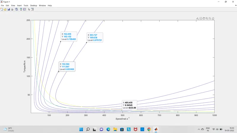
In the above plot at each point of the graph , we can get the value of speed,torque and Effciecncy of the motor.