Week-11 Challenge: Braking
Ans 1: Some assumed values are taken for the purpose of graph
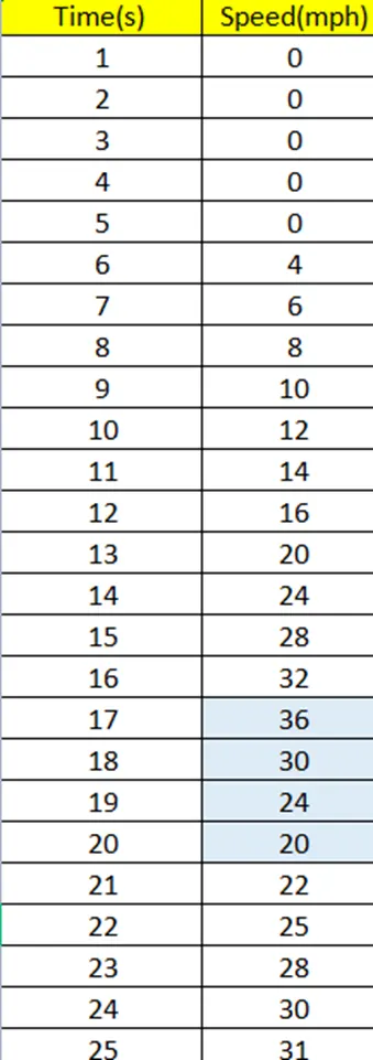
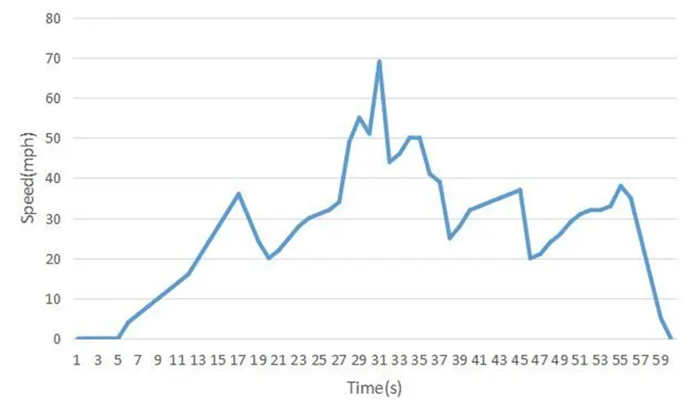
With the above data and attached excel file there is a graph between time and speed(mph). The speed mph converted into mps for calculation purpose
Calculations

were,
Mass = 1000Kg (Assumed)
6 decelerations were made during this drive cycle, so 6 braking energy is to be calculated and sum it up to get total braking energy for 60sec duration.
- 36 to 20mph = 16.09 to 8.94mps = 1/2 * 1000 * ( 16.09 - 8.94 )^2 = 25.56KJ
- 55 to 51mph = 24.58 to 22.79mps = 1/2 * 1000 * ( 24.58 - 22.79 )^2 = 1.60KJ
- 69 to 44mph = 30.84 to 19.66mps = 1/2 * 1000 * ( 30.84 - 19.66 )^2 = 62.49KJ
- 50 to 25mph = 22.35 to 11.17mps = 1/2 * 1000 * ( 22.35 - 11.17)^2 = 124.99KJ
- 37 to 20mph = 16.54 to 8.94mps = 1/2 * 1000 * ( 16.54 - 8.94 )^2 = 28.88KJ
- 38 to 00mph = 16.98 to 0mps = 1/2 * 1000 * ( 16.98 - 0 )^2 = 144.16KJ
Total Braking Energy = 25.56 + 1.60 + 62.49 + 124.99 + 28.88 + 144.16
Total Braking Energy = 387.68KJ
Ans 2: Torque - speed characteristics
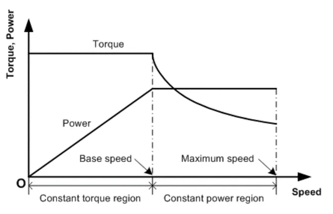
At start when the vehicle is at low speed the Torque proportional to it is high as given in the characteristics but at the time of deacceleration the motor also goes in constant power region as the speed is already high, where torque developed is usually low as compared to constant torque region. also, at the time of motor starting, motor draws high current due to transient.
As torque proportional to square of current, therefor torque value is high at this moment so that's why electric motor can’t develop braking torque at high speed similar to starting.
There are two types are breaking control strategies :
- Series Breaking:-
In this breaking both breaks are not applied simultaneously instead one break is applied after another. so, at a time, only one break is in actual functioning Regenerative breaking or Friction break.
- Parallel Breaking:-
In this breaking strategies both the breaks can be simultaneously applied.
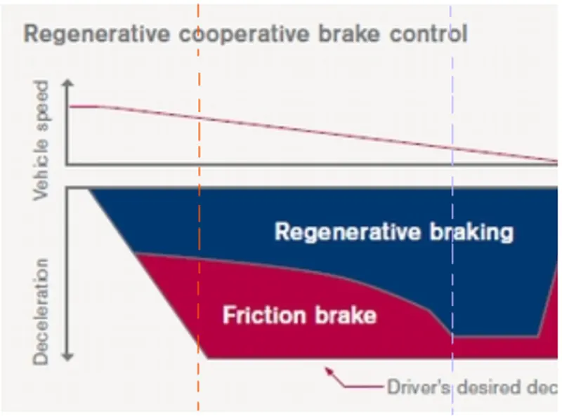
From above graph we can clearly say that when the speed is high (orange line in above fig) then friction break (mechanical break) is used and when the speed becomes low (purple line in above fig) then the regenerative breaking more used. So, we can say that in the low-speed breaking we can maximum apply regenerative break and charge our battery in an efficient manner.
Ans 3:
Given data - Kc (Copper loss) =0.2 , Kw (windage loss)=0.00001 ,Ki (Iron loss)= 0.08, Constant motor loss = 20
clc
clear all
speed = linspace(1,1000);
torque = linspace(1,250);
%Given data
kc = 0.2; %const for copper loss
ki = 0.008; %const for iron loss
kw = 0.00001; %const for windage loss
con= 20; %constant loss of motor
%making mesh
[P, Q] = meshgrid(speed,torque);
%for output power
out_power = P.*Q; %outputpower = speed * torque
%for input power
a = (Q.^2)*kc; %coppper loss
b = (P)*ki; %iron loss
c = (P.^3)*kw; %windage loss
in_power = a + b + c + con +out_power;
%to find out efficiency
efficiency = (out_power./in_power);
%contour will be ploted for this 10 points
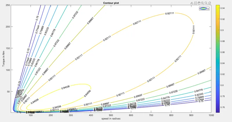
v = linspace(0.75,0.97,10);
%plotting countour
box on
grid on
contour(P,Q,efficiency,v,"linewidth",1.5,'ShowText','on');
colorbar
xlabel("speed in rad/sec");
ylabel("Torque in Nm");
title("Contour plot");
legend('a','b','c','d')
Result