Week-11 Challenge: Braking
1.For a defined driving cycle, calculate the energy required for braking.
A driving cycle is a series of data points representing the speed of a vehicle versus time. Driving cycles are produced by different countries and organizations to assess the performance of vehicles in various ways, as for example fuel consumption and polluting emissions
Under the condition of braking, some amount of energy is required to do the sam as that of energy required for accelerating the vehicle. Hence to calculate energy, use the acceleration energy equation,
Ek =1/2 mv²
Ek = kinetic energy (J)
m = mass of object (kg)
V= speed of the object (m/s)
Calculating the energy required for braking for a defined drive cycle:
From the drive cycle, there are 4 different situations of decceleration of which the energy has to be calculated.
First Braking = 24-15kmph = 6.67-4.17m/s
Second Braking = 35-30kmph = 9.72-8.33m/s
Third braking = 45-23 kmph = 12.5-6.39m/s
Fourth braking = 63-5 kmph= 17.5-1.39m/s
We consider the total mass of vehicle is 1750 kg
We know that the energy is given by
Ek = ½ m (Vi - Vf)
For 1st braking
Ek = ½ * 1750 * (6.67-4.17) = 2187.5 J
For 2nd braking
Ek = ½ 1750 * (9.72-8.33) = 1216.25 J
For 3rd braking
Ek = ½ * 1750 * (12.5-6.39) = 5346.25 J
For 4th braking
Ek = ½ * 1750 *(17.5-1.39) = 14096.25 J
Total Energy Required For Braking = 22846.25 J
Total Energy Required For Braking = 22.84625 KJ
2.Why electric motor can’t develop braking torque at high speed similar to starting? How electric and mechanical brakes are coordinated?
ANS: Braking is the change in the motion of a vehicle from a starting speed level to a lower speed level. The act of braking,if sustained for a sufficient time,can either bring a vehicle to a lower speed than it started with or it can bring it to complete rest. So, the act of brakinf bring about deceleration which is decrease in the speed of the vehicle over a period of time which corresponds to the speed values at those times. bracking isan act which is desired in speed control application and in the case of vehicle,they are very much necessary to ensure the safety of the driver and the control of the vehicle.There are several methods for performing braking in vehicle whether they are conventional vehicle or EV's or HEV's.
Mechanical Braking: In a conventional IC engine vehicle,there is only one physical braking mechanism that can be performed and that is done with the brake pads/Discs on to the wheels of vehicle. The friction that arises between the rotating wheels and the stationary brake pads/discs will decrease the speed of the .Another method od braking in conventional vehicles is called "engine braking".In this method, the throttle(accelerator pedal)is released,and the gear is changed to a lower gear (in manual transmission vehicle),which will result in the deceleration of the vehicle.This occurs via the "Manifold effect" whereby,the releasing of the accelerator pedal leads to the stopping od the fuel flow to the engine cylinder. This also stops the air flow resulting in a negative traction torque. In heavy duty vehicle e.g. Trucks,lorries,engine braking is very useful because it hekps to prevent the high heat build up in the brake pads/discs which would be generated if they were only used,so,engine braking is useful as it allows for the desired control while reducing wear and tear on the physical braking mechanism.
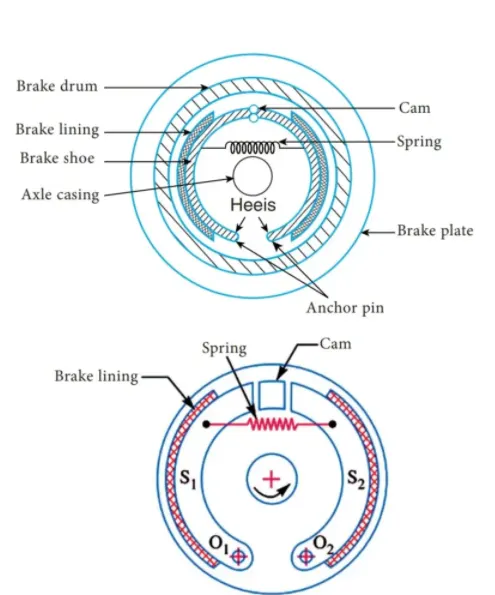
Electric Braking :In motors and evs/Vs various methods of taking av One method is using a broke motor which conents of a DC rectifer, o magnes, springe and o friction disc. the mechanism of the broke motor involves the recter giving a signet to disrupt o magnetic field which will influence the springs to expand and apply a force on the friction des which will come into contact with the moving part that is in contact with the rotor When the vehicle le accalating or moving with constant speed, the motor stil receives its 3-phase AC supply from the inverter and so the brokes are not applied. This DC rectifier relays no signal to the magnetic field so that the springs stay in their stationary position and do not force any contact on to the friction discs. However when vehicle is not accelerating the 3-phase AC supply from the inverter is cutoft, causing the brokes to be applied The DC magnetic field is dierupted by an air gap which causes the springs to get excited and expand and apply force on to the friction disc to produce braking action
EVE and HEV have the brilliant feature of regenerative braking which is where during the act of broking the motor begins to operate as a generator and instead produces electrical energy. Essentially, when a vehicle decelerates the change in the kinetic energy of that vehicle is used to produce a torque on the motor and thereby producing electricol energy vio the generator effect which can be stored by the battery or be diverted for another powering purpose. The electricity generated by the regenerative braking phenomenon is referred to os back emf because it produces a current that travels in the opposite direction to the conventional current For regenerative broking to occur, the rotor of the motor has to rotate at a speed that is greater than the synchronous speed. This will result in the back wmf being greater than the terminal voltage so that the potential difference is strong enough to influence the current to flow in the opposite direction Using regenerative braking not only decelerates the vehicle, but also increases the efficiency and the energy savings of EVs and HEVS
Another method of braking in EVE and HEVs is referred to as "dynamic braking in this method of braking the supply voltage powering the motor is disconnected and instead a resistor is conected. The absence of the resistor would result in significant trictional and windoge losses which would decrease the efficiency of the vehicle and lead to longer braking times. This is not desirable because a good broke needs to bring the vehicle to rest within a certain amount of time and done in a safe manner. With the resistor fitted instead, the braking time can be reduced significantly
in addition, another braking method in motors and EVS/HEVs is referred to as terminal voltage reversal in this method of broking, two separate voltage sources are used with different polarities as well as a switch. When the motor is running normally, the first voltage source is the main supply of power to the motor and creates a current flow in the conventional current. When the braking action is desired, the switch is closed to connect the second voltage supply in to the circuit and disconnect the first voltage source. Because the second voltage source has a reversed polarity, the current flow in the circuit to the motor is reversed thereby slowing the motor down by making its rotor rotate in the reverse directionle negative torque. This method is not always preferred due to the fact that it produces a severe braking and generates high levels of braking torque. So, a braking resistor is also used in the circuit and will come in to use whenver the second voltage source is connected to powcer the motor.
Control strategies:
From these various braking methods, it is obvious that both mechanical and electrical braking is useful and both have their benefits and drawbacks, in regards to a vehicular application, depending on the type of vehicle either one of both types are utilised. In the case of conventional vehicles, only mechanical braking consisting of friction braking and engine braking is utilised whereas in HEVS/EVS, both are utilised. In HEVS/EVS using both mechanical and electrical braking means that the braking application can get the advantages of both types and minimize the disadvantages as much as possible. HEVS and EVS use controls strategies for controlling the braking method and deciding which brokes to apply and when to apply them. These control strategies are referred to as braking modes and they will find a compromise between the mechanical and electrical braking methods to see which is the most efficient at its job,
For instance, at lower speed levels, it may be more suitable to use mechanical brakes Le friction braking because these brakes will be more than capable to brake the vehicle and not generate too much heat and thus will not produce too much wear and tear for the brake pads/discs. However at higher speed levels, it would be more suitable to use electrical braking. This is because electrical braking is more effective, it won't generate nearly as much heat as mechanical brakes would Electric braking also is more efficient and energy saving because at higher speeds, more kinetic energy will be carried by the vehicle and thus, regenerative braking can occur to convert that kinetic energy in to electrical energy to be stored back in the battery. It mechanical brakes were used instead, high amounts of heat would be generated and would lead to wear and tear of the brake pads/discs over time. The high heat generation also means that the dissipation of the kinetic energy is wasted in to energy that cannot be reused which reiterates its inefficiency compared to the electric brakes. In addition, the electric brakes would also be smoother and more gradual and not sudden like the mechanical brakes would which would make the braking action more comfortable and safer for the passengers.
So these control strategies Le, braking modes will know from the vehicle data, which type of braking is the best to use depending on its current state of motion. There are various braking modes for different situations the vehicle may face and by utilizing these control strategies, the vehicle can be operating at the highest efficiency at all times and make the best use of the 2 braking mechanisms without damaging or sacrificing one for the other.
Braking Torque:
The starting torque of a motor is the torque developed by the motor at no speed and this is a moderately high value. At high speeds, electric motors cannot develop braking torques compared to their starting torques. This is because, the greater the speed of the vehicle, the greater the braking torque that is required to brake the vehicle. This is simply because at higher speeds, more force is needed to oppose the rotation of the rotor of the motor and this means a greater torque Le. braking torque. So, when a vehicle is travelling at high speeds, a larger braking torque is needed to brake the vehicle. However, when a motor is starting, its starting torque Le. torque at no speed is the highest torque the motor can achieve. This is because the speed - torque characteristics of a motor are characterized by a linear relationship. If we were to plot a graph of the angular speed of the rotor on the y-axis and the torque on the x-axis, the plot would show a straight line with a negative gradient. The starting torque is represented by the x-intercept of this plot in the first quadrant i.e. the forward motoring region. In this way, the torque generated by the starting of the motor will not be similar to the braking torque that is generated at higher speeds. Also, at higher speeds, the terminal voltage of the voltage source increases, and so the torque values will differ further from the starting torque.
3.Make a MATLAB program which plots contour of given motor speed, torque and efficiency values. Attach the code as a .m file attach a screenshot of all the plots.
ANS:
A contour plot that shows the characteristics of the speed, torque and the efficiency of a motor is referred to as an efficiency map. Contour plots are very useful as they make it very easy to understand which operating states result in the highest efficiencies of the motor. In this way, a manufacturer can design a motor knowing which applications it will be useful for depending on the speed, the torque it achieves at that speed and the efficiency of the motor which operates at those values.
In order to plot this, we need the specifications of a motor. In this question I am taking generic values for the specifications of the motor as well as for the losses that occur in the motor operation.
in the MATLAB script, I begin with the clear all, close all and clc commands. Then, I create arrays for the speed and the torque of the motor using the inspace' command. For the speed, I am taking a range of values from 0 to 2000 radians per second whereas for the torque, I am taking a range of values from 0 to 300Nm
These arrays are then used to create 2D grid coordinates using the meshgrid command. These coordinates will help in the creation of the contour plot. In order to find the efficiency of the motor, we need to consider the various losses that occur in the motor's operation.
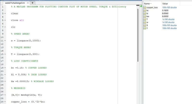
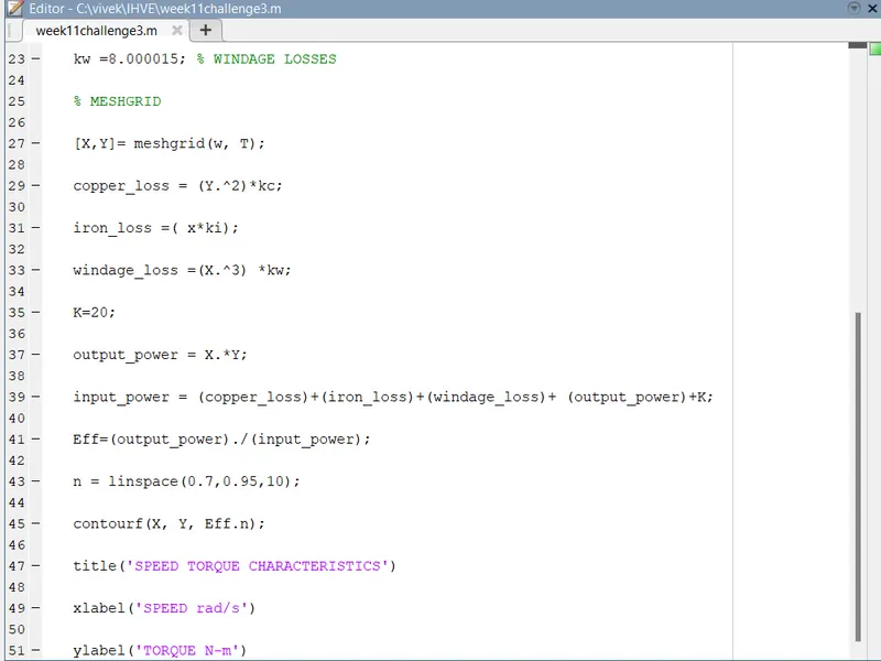
% A MATLAB PROGRAMM FOR PLOTTING CONTOUR PLOT OF MOTOR SPEED, TORQUE & Efficiency
clear
close all
clc
% SPEED ARRAY
w = linspace(0,1000);
% TORQUE ARRAY
T = linspace(0,300);
% LOSS COEFFICIENTS
kc =0.18; % COPPER LOSSES
ki = 8.006; % IRON LOSSES
kw =8.000015; % WINDAGE LOSSES
% MESHGRID
[X,Y]= meshgrid(w, T);
copper_loss = (Y.^2)*kc;
iron_loss =( x*ki);
windage_loss =(X.^3) *kw;
K=20;
output_power = X.*Y;
input_power = (copper_loss)+(iron_loss)+(windage_loss)+ (output_power)+K;
Eff=(output_power)./(input_power);
n = linspace(0.7,0.95,10);
contourf(X, Y, Eff.n);
title('SPEED TORQUE CHARACTERISTICS')
xlabel('SPEED rad/s')
ylabel('TORQUE N-m)
result:
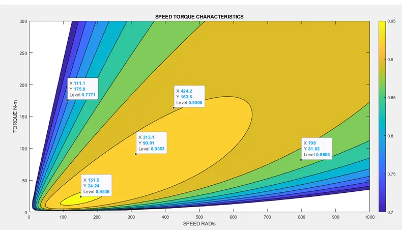
From the output graph,you could see that only at a particular speed and torque the efficiency is at maximum i.e 95%.
where,speed x=151 rad/s @24 N-m Torque. As the speed increases the efficiencies of yhe motor will be reduced.