Week -2
1.Make a Simulink model of Doorbell using solenoid block
AIM:- Make a Simulink model of Doorbell using solenoid block with the following details
REQUIRED:-
Create a situation where is closed for 2 seconds and then released
Observer the physical movement of the plunger
Doorbell working:-
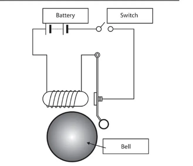
- This is a battery and this striker switch this going that when we hear the sound we can so this circuit it be formed
- We take a rod NS of soft iron and wind coil C of insulated copper wire around it. When we connect the two ends of the copper coil to a
battery, an electromagnet is formed. The iron rod inside the coil
becomes a strong electromagnet on passing a current
- This electromagnet the attract toward the process the striker the going and the sound produced but notice what happens when the striker as
soon as soft iron is shift away from its circuit breaker no longer connects the wire length the terms of the battery and the circuit breaker the
current stop following so this electromagnet gets demagnetized
- Which the soft iron goes back to this start position this process will continue until the switch open again as soon as release the push button
the circuit breaks end bell stopping the rings
Simulink block required for the Model:-
Physical & Simulink Block Procedure:-
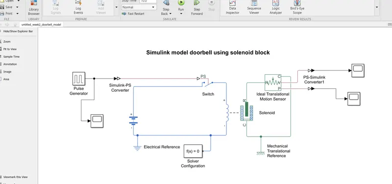
- This is Pulse generator used to generate square wave pulses at regular interval the signal to input into The block waveform parameter give apply the value Amplitude 1, Pulse Width 50 Period 4 sec, and Phase delay determine the shape of the output waveformThe
- Simulink-PS Converter block converts the input Simulink signal into a physical signal. Use this block to connect Simulink sources or other Simulink blocks to the inputs of a Physical Network diagram.
- The Switch block represents controlled by an external physical signal. If the external physical signal PS is greater than the threshold, then the switch is closed, otherwise the switch is open.
- The closed resistance is defined by parameter R closed, and the open conductance is defined by parameter G open. Both parameters must be greater than zero.
- Battery block Parallel model if you select infinite for the battery charge 50Hr.A capacity parameter this block model the battery as a series resistance and constant voltage source
- When the Switch is made on for the first two seconds and then turned off current passing through the solenoid makes the plunger to create displacement according to the Solenoid properties like mass off then plunger
- Ideal Translational Motion Sensor block represents a device than converts an across variable measured between two mechanical translational nodes into a control signal proportional to velocity or position.
- Connections R and C are mechanical translational conserving ports that connect the block to the nodes whose motion is being monitored. Connections P are physical signal output ports for velocity and position,
- Solver Configuration block specifies the solver parameters that your model needs before you can begin simulation. Each physical network represented by a connected Simscape block diagram requires solver settings information for simulation.
- PS-Simulink Converter block converts a physical signal into a Simulink output signal. Use this block to connect outputs of a Physical Network diagram to Simulink scopes or other Simulink blocks.
- Scope block output seeing Display signals generated during simulation.
- Mechanical Translational & Electrical Reference block represents anelectrical ground.
- Simscape Simulink & Physical block to create to the output in scope Plot.
Plotting the input and output graph:-
Input:-
Output:-
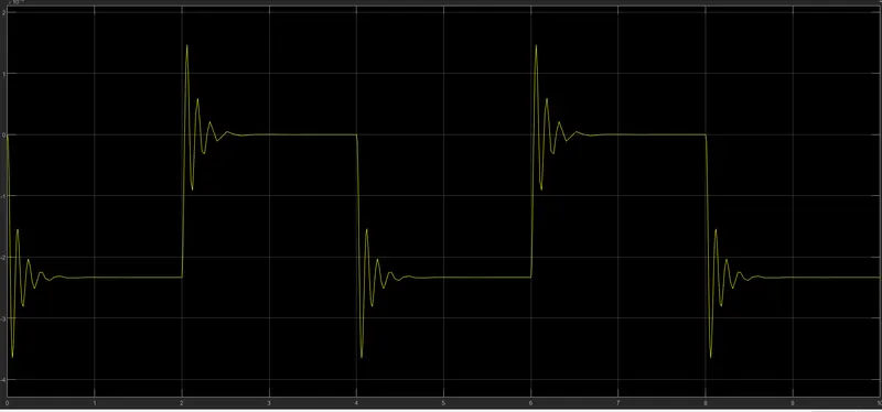
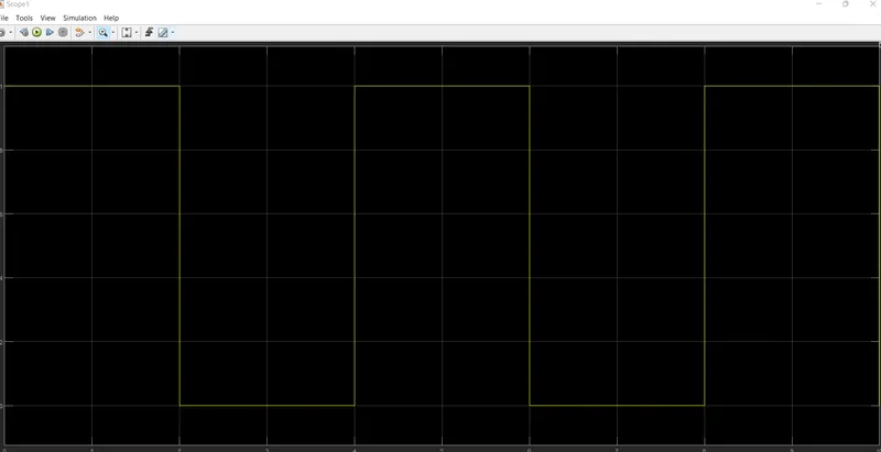
- After doorbell Simulink model situation where is closed for 2 seconds and then released this output graph visualized.
- This process will continue until the switch open again as soon as release the push button the circuit breaks end bell stopping the ring
Conclusion:-
That’s Simulink model completed to a situation where the switch is closed for 2 seconds and then released. Observe the physical movement of the plunger.
2.Use a thermistor to sense the temperature of a heater & turn on or turn off the fan
Condition -Temperature source: 20 °C from 0 to 10 seconds, 27 °C from 10 to 30 seconds, 23 °C from 30 to 50 seconds
Fan conditions: ON if the temperature above 25 °C, OFF otherwise
Blocks used in model:
- Repeating Sequence Stair
- Controlled Temperatrure Source
- Thermistor
- Resistor
- Voltage sensor
- Battery
- Switch
- Lamp
- Scope
- Display
- PS-Simulink Converter
- Simulink-PS converter
- solver Configuration
- Translational Electromechanical Converter
- Ideal Translational Motion Sensor
Simulink model:-
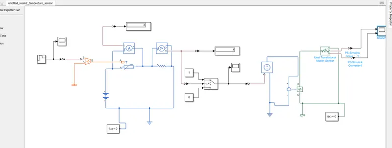
input scope :-
Model explanation:-
A Repeating Sequence Stair is given as input to the thermistor through a controlled temperature soure. The difinition of repeating sequence stair block is given below .
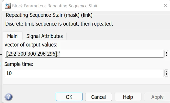
The conditons of the temperature sourse is defined inside the above window. The sample time was tsken as 10s and the whole simulation time was taken as 50s.
battery and a resistor is connected in the thermistor circuit. A voltage sensor was given accross this resistor to measure the voltage change during
different temperature inputs. The resistor of this resistor can be set to any value ,but it should not be changed once the threshold voltage is found.
The threshold temperature was given as 25 degree celsius and the corresponding voltage over the resistor was found out,Celsius or 298 k. The output from the voltage was also given into a switch which is link to the scope
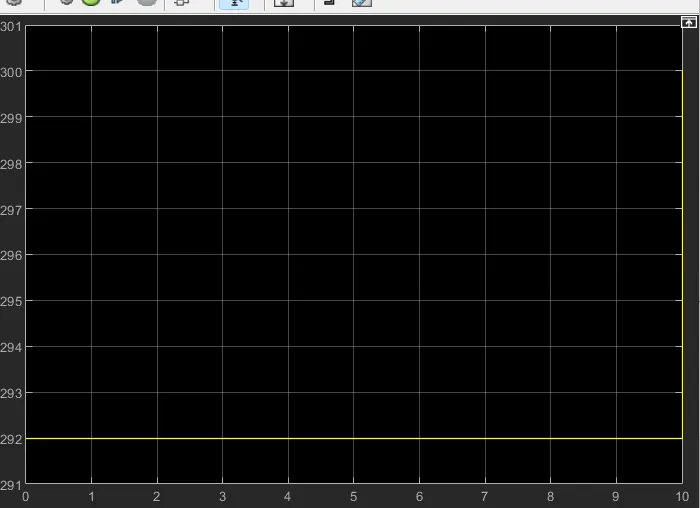
scope output(result):-