Week-11 Challenge: Braking
Objective
For a defined driving cycle, calculate the energy required for braking.
In electric vehicle Drive cycle is required by vehicle for acceleration as well as deacceleration of vehicle also. As we require to stop vehicle in
stipulated time, we cannot allow vehicle to stop as per its inertia value, for stopping vehicle we require to apply brake. Braking of vehicle
require to deaccelerate vehicle to lower speed within a given time.
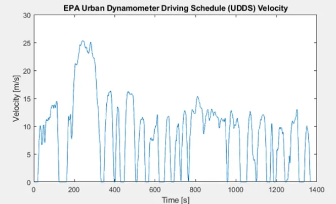
Refer the attached sheet for complete calculation of Deacceleration energy require in UDDS cycle ,
To reduce speed from 80 to 40 Kmph in 20 sec = 292 KJ
To reduce speed from 80 to 0 Kmph in 10 sec = 560 KJ
2 . Why electric motor can’t develop braking torque at high speed similar to starting? How electric and mechanical brakesare
coordinated?
The torque-Speed characteristic of motor is not exact same in the braking and motoring region.
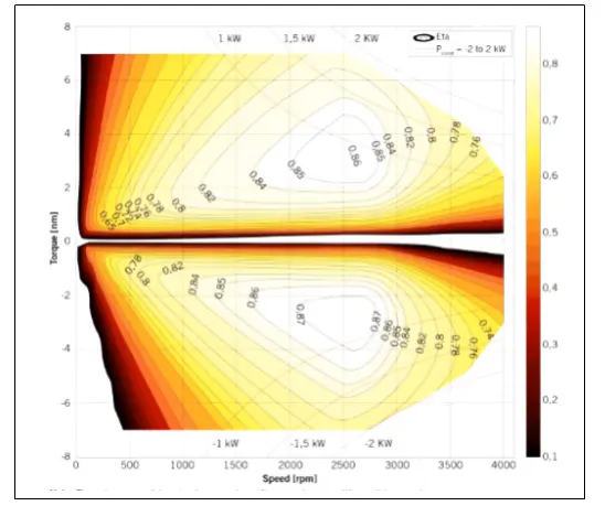
This is torque-speed contour plot of motor with efficiency.
We can see that, at the time of accelerating vehicle at starting the maximum torque available motor is operating at constant torque region,
in that motor will have maximum torque available, but as motor starts deaccelerating motor characteristics are shifted towards braking
region, in this we don’t have max torque available for braking as motor is already running at higher speed.
Due to this operation, electric motor can’t develop braking torque at high speed similar to starting
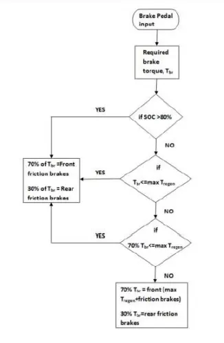
Electrical and mechanical braking systems can are coordinated by using Brake strategy subsystem
1) Serial Braking Strategy
2) Parallel Braking Strategy
Implementation of serial braking strategy
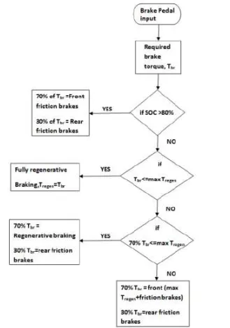
Implementation of parallel Braking :
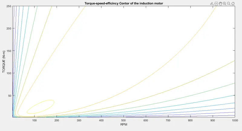
3. Make a MATLAB program which plots contour of given motor speed, torque and efficiency values. Attach the code as a .m
file attach a screenshot of all the plots.
clear all;
close all;
clc;
Torque= linspace(1,250,250) %Input Torque
Speed= linspace(1,1000,250) %Input Speed
[w,T]= meshgrid (Speed,Torque); %Converting to 2D array
Kc= 0.3; % Coppper loss constact
Ki= 0.009; % Iron loss Constant
Kw= 0.00005; % Windage loss constat
C=30; % constant loss
Pout= w.*T; %Output Power
C_loss=Kc*(T.^2); %Copper loss
I_loss=Ki*w; %Iron loss
W_loss=Kw*(w.^3); %Windage loss
Pin=Pout+C_loss+I_loss+W_loss+C; %Input power
eff=Pout./Pin
contour(Speed,Torque,eff)
title('Torque-speed-efficincy Contor of the induction motor');
xlabel('RPM');
ylabel('TORQUE (N-m)');
Result:-