Week-11 Challenge: Braking
OBJECTIVE :
- For a defined driving cycle, calculate the energy required for braking.
- Why electric motor can’t develop braking torque at high speed similar to starting? How electric and mechanical brakes are coordinated?
- Make a MATLAB program which plots contour of given motor speed, torque and efficiency values. Attach the code as a .m file attach a screenshot of all the plots.
SOLUTION :
- For a defined driving cycle, calculate the energy required for braking.
ENERGY REQUIRED FOR BREAKING :
When a force is applied to the brakes of a vehicle, there is work done on the friction between the brakes and the wheel. This reduces the kinetic energy of the vehicle, slowing it down and causing the temperature of the brakes to increase.
Decelerating from very high speeds too quickly can cause several problems:
The brakes could overheat and the material they are made from could shatter. This will lead to the driver losing control.
Very high temperatures near the tyres could cause the tyres to explode. This will lead to the driver losing control.
A high deceleration needs a high force (Newton's second law), and these high forces can seriously injure the driver.
The energy required for braking can be calculated using Newton's second law. Let’s assume a drive cycle, FTP 75 with a total gross weight of 1000 Kg
The acceleration/ deceleration of the car is given by:
Deceleration =change in velocity/time
= (Final velocity – Initial Velocity)/ Time
( Since we know that : acceleration A = (v-u)/t m/s )
and the kinetic energy is given by following equation :
K.E = 1/2* (m*V2) Joules.
This energy can be converted to kWh when multiplied with a factor of 2.7778e-7
The total energy consumed for Braking is 140 kWh
2. Why electric motor can’t develop braking torque at high speed similar to starting? How electric and mechanical brakes are coordinated?
The process of applying brakes can be termed as braking.
Basically, there are two types of braking:
Mechanical Braking
Electrical Braking
now both of them can be explained briefly as follows :
Mechanical braking:
All act by generating frictional forces as two surfaces rub against each other.
The stopping power or capacity of a brake depends largely on the surface area of frictional surfaces as well as on the actuation force applied.
The friction and wear encountered by the working surfaces are severe.
Thus, the durability of a brake or service life between maintenance depends heavily on the type of material used to line the shoe or pad.
Mechanical brakes are assemblies consisting of mechanical elements for the slowing or stopping of shafts in equipment drives. They use levers or linkages to transmit force from one point to another. Braking slows or stops the movement of the coupled shafts.
There are several types of mechanical brakes like,
Drum brakes: Commonly used on automobile rear wheels, work when shoes press against a spinning surface called a drum
Disc brakes: Constructed of brake pads, a calliper, and a rotor. During operation, the brake pads are squeezed against the rotor. Cone brakes are made with a cup and a cone, which is lined with heat and wear resistant material. During actuation, the cone is pressed against the mating cup surface.
Engine Braking: A compression engine brake is a device that can convert a diesel engine into an air compressor, a power absorbing device. These devices are used in trucking applications to provide a means for retarding the vehicle, supplementing the normal vehicle braking system. The retarding operation is under full control of the vehicle operator and can be used simultaneously with the normal service brakes. Engine brakes can be installed at any time to a new or used vehicle for most applications.
Exhaust Braking mechanism: An exhaust brake works by restricting the flow of exhaust gases through the engine Heavy goods vehicles can often require increased braking, in situations where friction brakes could overheat and fail. This is achieved by using an exhaust brake. It achieves this by closing a butterfly valve located in the exhaust manifold. This maintains high pressures in the exhaust manifold, and the engine cylinders, which in turn, acts as a brake against the engine rotating. This then slows the road wheels through the transmission, or power train.
Electrical braking:
Electrical Brakes are used to reduce or cease the speed of motors. We know that there are various types of motors available (DC motors, induction motors, synchronous motors, single phase motors etc.) and the specialty and properties of these motors are different from each other, hence this braking method also differs from each other. But we can divide braking in to three parts mainly, which are applicable for almost every type of motors.
- Regenerative Braking
- Plugging type braking
- Dynamic braking
Regenerative Braking:
Regenerative braking takes place whenever the speed of the motor exceeds the synchronous speed. This baking method is called regenerative braking because here the motor works as generator and supply itself is given power from the load, i.e., motors. The main criterion for regenerative braking is that the rotor must rotate at a speed higher than synchronous speed, only then the motor will act as a generator and the direction of current flow through the circuit and direction of the torque reverses and braking takes place. The only disadvantage of this type of braking is that the motor must run at super synchronous speed which may damage the motor mechanically and electrically, but regenerative braking can be done at sub synchronous speed if the variable frequency source is available.
Plugging Type Braking:
Another type of braking is Plugging type braking. In this method the terminals of supply are reversed, as a result the generator torque also reverses which resists the normal rotation of the motor and as a result the speed decreases. During plugging external resistance is also introduced into the circuit to limit the flowing current. The main disadvantage of this method is that here power is wasted.
Dynamic Braking:
Another method of reversing the direction of torque and braking of the motor is dynamic braking. In this method of braking of the motor which is at a running condition is disconnected from the source and connected across a resistance. When the motor is disconnected from the source, the rotor keeps rotating due to inertia and it works as a self-excited generator. When the motor works as a generator the flow of the current and torque reverses. During braking to maintain the steady torque sectional resistances are cut out one by one.
electric motor can’t develop braking torque at high speed like starting due to varying limitations and performance characteristics.
For an ideal Four – Quadrant or Two – Quadrant motor, its performance characteristics may look similar especially in its Forward Motoring and Braking operation.
In practical case of braking period, the motor must function as generator. So, it must have suitable braking characteristics.
That is : even though, if a motor produces a peak torque value of 100N.m at Forward motoring mode, the same value can’t be achieved by the motor during its Forward braking operation.
The peak value of acceleration achieved by motor can’t be achieved during the deceleration
To run at peak value of forward braking, the power converter must also be modified with complex bi-directional circuits, helping to charge batteries.
The battery also be able to accept high charge/discharge rate
electric and mechanical brakes can be coordinated in mostly two ways,
Series
Parallel
In series braking system,
The regenerative braking system could restore kinetic energy and potential energy to a battery or any other forms of power during braking, is a special system for electric and hybrid electric vehicles.
However, the large current produced by the generator during braking would affect battery performance and shorten battery life.
A hybrid-power system is an excellent energy storage system, in which an ultra-capacitor bank and a battery pack are connected through a DC/DC power converter.
The ultra-capacitor in this system can store instantaneous large currents quickly, which is able to protect the battery from large currents, suggest that the ultra-capacitor is able to restore the regenerative energy very quickly, which will improve starting and acceleration performance, extend driving range, and increase fuel economy
In parallel braking system,
The regenerative braking system is the own system of Electric and Hybrid Electric Vehicle.
The system can restore the kinetic energy and potential energy, used during start and accelerating, into battery through electrical machine.
The total brake force is composed of friction brake force on front axle, friction brake force on rear axle and regenerative brake force when a vehicle equipped with regenerative braking system brakes.
The parallel brake strategy is not only safe enough but also can restore the largest amount of the brake energy.
An example for Parallel Braking system is Nissan’s EDIB technology in Leaf :
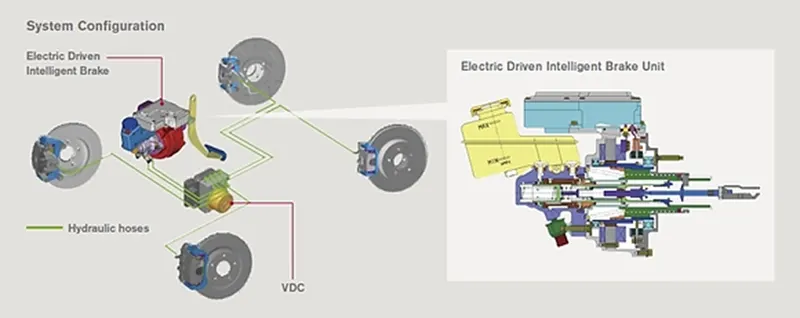
The model’s features are;
Safe braking
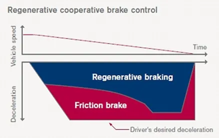
EVs and hybrid vehicles use regenerative braking, which utilizes the motor to convert the kinetic energy during deceleration into electrical energy.
With energy regeneration, an EV can run on less electricity and a hybrid vehicle on less fuel.
The EDIB (Electric Driven Intelligent Brake) allows and controls optimization of the regenerative brake and regular friction brake (hydraulic brake).
Technology Functionality
After stepping on the brake pedal, the system produces natural and adequate braking force that corresponds to the operation.
The amount of energy regeneration also needs to be increased as much as possible.
EDIB (Electric Driven Intelligent Brake) controls the regenerative brake and friction brake to support both requirements.
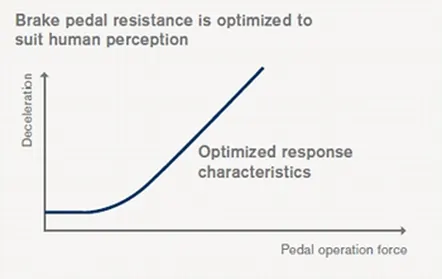
Further, it also controls the reactive force from the pedal to unify the feeling when stepping down on the pedal and the sense of deceleration.
Technology Configuration
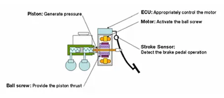
When the driver steps on the brake pedal, the stroke sensor detects operation of the brake.
That information is communicated to the ECU and controls the motor.
The motor engages the piston and amplifies the friction brake's pressure (hydraulic pressure).
Through optimum control of the friction brake's hydraulic pressure, the energy regeneration outcome is maximized.
3. Make a MATLAB program which plots contour of given motor speed, torque and efficiency values. Attach the code as a .m file attach a screenshot of all the plots.
close all
clear all
clc
% x - axis corresponds to Motor Speed, w in rad/s
% y - axis corresponds to Torque, T in N.m

x = linspace(1,1000); % Speed of Motor in rad/s
y = linspace(1,250); % Torque produced by Motor in N.m
%Allocate motor Core and Copper loss constants
kc = 0.2; %Copper loss constant
ki = 0.008; %Iron loss constant
kw = 0.0001; %Windage loss constant
conL = 20; %Constant motor loss
%To make an array of mesh
[X, Y] = meshgrid(x,y);
%To calculate Output Power,
Pout = (X.* Y); %Power = Torque * Speed
%To find losses
B = (Y.^2)*kc; %Equation to find Copper loss
C = X.*ki; %Equation to find Iron loss
D = (X.^3)*kw; %Equation to find Windage loss

%Relation between Input Power and Output Power
%Input Power = Output Power + Losses
Pin = Pout + B + C + D + conL;
Z = Pout./ Pin; %To calculate efficiency
%Set the efficiencies for which Contour to be plotted
V = [0.7:0.05:0.95];
box off
grid off
contour(X, Y, Z, V)
xlabel('Speed of Motor (rad/s)');
ylabel('Developed Torque (N.m)');
hold on
%Plot contour for Output Power
%The array for Output Power is already calculated, to draw contour @3-5kW
V = [4000:2000:10000];
contour(X, Y, Pout, V);
hold off
title('Plot for efficiency Contour, Speed vs Torque')
end
Plot :
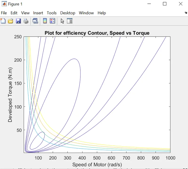
DETAILED EXPLANATION :
The most efficient region in the contour is the innermost elliptical shape with efficiency over 90%
It is evident from the contour that, the efficiency decreases as values are away from the innermost shape
As the contour lines move away from the centre, the efficiency falls even to 70%
It is optimal for the Motor to operate between the inner most ellipse and its adjacent one for maximum efficiency and performance
Conclusions :
1. The total energy consumed for Braking is 140 kWh
2. The parallel brake strategy is not only safe enough but also can restore the largest amount of the brake energy and
the motor engages the piston and amplifies the friction brake's pressure (hydraulic pressure).
through optimum control of the friction brake's hydraulic pressure, the energy regeneration outcome is maximized.
3. As the contour lines move away from the centre, the efficiency falls even to 70%
It is optimal for the Motor to operate between the inner most ellipse and its adjacent one for maximum efficiency and performance
Gdrive link:
https://drive.google.com/drive/folders/1Z90bEstG9BkENbb4Rhvs2nGIhn0tG93e
References :
- Mathworks documentation
- Wikipedia
- Google images