Week-11 Challenge: Braking
AIM : For a defined driving cycle, calculate the energy required for braking.
| 0 | 0 |
| 1 | 1 |
| 2 | 3 |
| 3 | 6 |
| 4 | 9 |
| 5 | 12 |
| 6 | 15 |
| 7 | 18 |
| 8 | 21 |
| 9 | 24 |
| 10 | 27 |
| 11 | 30 |
| 12 | 33 |
| 13 | 36 |
| 14 | 39 |
| 15 | 42 |
| 16 | 45 |
| 17 | 48 |
| 18 | 51 |
| 19 | 54 |
| 20 | 57 |
| 21 | 60 |
| 22 | 63 |
| 23 | 66 |
| 24 | 69 |
| 25 | 72 |
| 26 | 75 |
| 27 | 78 |
| 28 | 81 |
| 29 | 84 |
| 30 | 87 |
| 31 | 90 |
| 32 | 93 |
| 33 | 96 |
| 34 | 99 |
| 35 | 102 |
| 36 | 105 |
| 37 | 108 |
| 38 | 111 |
| 39 | 114 |
| 40 | 117 |
| 41 | 120 |
| 42 | 123 |
| 43 | 126 |
| 44 | 129 |
| 45 | 132 |
| 46 | 135 |
| 47 | 138 |
| 48 | 141 |
| 49 | 144 |
| 50 | 147 |
| 51 | 150 |
| 52 | 153 |
| 53 | 156 |
| 54 | 159 |
| 55 | 162 |
| 56 | 165 |
| 57 | 168 |
| 58 | 171 |
| 59 | 174 |
| 60 | 177 |
| 61 | 180 |
| 62 | 183 |
| 63 | 186 |
| 64 | 189 |
| 65 | 192 |
| 66 | 195 |
| 67 | 198 |
| 68 | 201 |
| 69 | 204 |
| 70 | 207 |
| 71 | 210 |
| 72 | 213 |
| 73 | 216 |
| 74 | 219 |
| 75 | 222 |
| 76 | 225 |
| 77 | 228 |
| 78 | 231 |
| 79 | 234 |
| 80 | 237 |
| 81 | 240 |
| 82 | 243 |
| 83 | 246 |
| 84 | 249 |
| 85 | 252 |
| 86 | 255 |
| 87 | 258 |
| 88 | 261 |
| 89 | 264 |
| 90 | 267 |
| 91 | 270 |
| 92 | 273 |
| 93 | 276 |
| 94 | 279 |
| 95 | 282 |
| 96 | 285 |
| 97 | 288 |
| 98 | 291 |
| 99 | 294 |
| 100 | 297 |
for the above data obtained drive cycle :
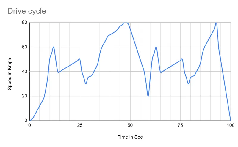
Vechicle weight is 1000kg
| Final velocity | Time required | Deceleration | energy required | braking power | braking energy | |
| 40 | 3 | 1.85 | 277778 | 92592.6 | 25.7 | |
| 30 | 3 | 1.85 | 222222 | 740741 | 20.6 | |
| 20 | 11 | 1.52 | 833333 | 7575.6 | 21 | |
| 40 | 3 | 1.85 | 277778 | 92592.6 | 25.7 | |
| 30 | 3 | 1.85 | 222222 | 74074.1 | 20.6 | |
| 0 | 7 | 3.17 | 888888 | 26984.2 | 35.3 | |
Total Braking energy required 148.5(Wh).
AIM 2 : Why electric motor can’t develop braking torque at high speed similar to starting? How electric and mechanical brakes are coordinated?
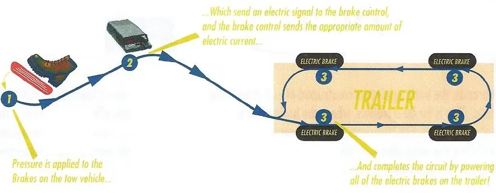
Electric Brakes : The magnet in the backing plate has 2 conductor wires which tap directly into the trailer wiring. When electricity is on, it magnetizes the brake magnet. The magnet is attracted to the drum face. When it contacts this area, the friction causes it to rotate, which moves the actuating arm, and pushes the shoes out against the drum. Those shoes have a special brake pad material on them that resists the heat caused by that friction. When the shoes press against the inside of the drum, they prevent the hub, and consequently the wheel that's touching the ground from spinning.An electrical connection on the trailer plugs into the connector on the vehicle. There are electrical wires running from the trailer connector back to each brake on the axle, as well as to the trailer lights, to create a complete circuit. When the driver steps on the brakes it sends a current to the brake control in the vehicle. The brake control then sends a current back to the trailer to activate the brakes. Here's what that looks like:
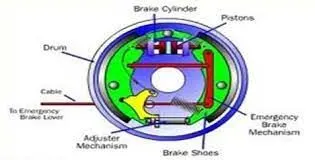
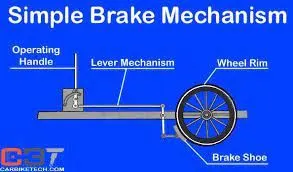
Mechanical brakes : Mechanical brakes function via force delivered to a body in rotary or linear motion, such as a shaft, axle or wheel, to slow or stop motion. They are often in an assembly with a mechanical clutch for engaging and disengaging shafts.
Friction-based brakes use a brake liner consisting of a coarse and rugged material tightened or pressed against a body in motion to decelerate. They generate noise as well as heat. The engaged surfaces degrade and brake capacity decreases with every cycle, making regular inspection and replacement a necessity. Friction-type brakes are heavily used in automotive applications. Drum brakes, cone brakes and disc brakes are all friction brakes.
Mechanisms besides friction are used in other types of mechanical brakes.
Toothed brakes have tooth-shaped contact surfaces that transmit power without slippage or heat generation. Teeth are engaged only when stopped or running at slow speeds (<20 rpm). Because the torque comes from the teeth, there is no slipping when the brake is engaged. Toothed brakes are used in access control systems, indexing systems in machine tools and labeling machines.
Non-contact brakes use technology such as a magnetic field or eddy currents to provide the braking action. Braking force is generated proportionately to velocity. Because there is no friction with eddy current and magnetic brakes there are no parts that wear out. One disadvantage, however, is that they do not have any holding force for stationary objects. Trams and trains, aircraft, industry and robotics are common applications for non-contact brakes.
A wrap-spring clutch and brake work by connecting an input shaft and output shaft with an interference fit helical clutch spring. When the input shaft rotates in the direction of the wind of the clutch spring, torque is transmitted to the output shaft. A separate brake spring spins until the brake spring control tang is locked, which tightens the brake spring around the output shaft in position to a stationary brake hub that is bolted to a plate. Simultaneously the clutch spring releases. Wrap-spring brakes provide precise stopping (± 0.5°) in industrial machinery, but fully mechanical wrap-spring clutches and drives are limited to smaller sizes; larger sizes are electromagnetic. This type of brake is used in index systems, industrial and aeronautical applications, weaponry actuators, scanning equipment, and medical devices such as hospital beds and wheelchairs.
coordination of electrical and mechanical braking :
The parallel assist strategy can use the electric motor in a variety of ways:
- The motor can be used for all driving torque below a certain minimum vehicle speed.
- The motor is used for torque assist if the required torque is greater than the maximum producable by the engine at the engine’s operating speed.
- The motor charges the batteries by regenerative braking.
- When the engine would run inefficiently at the required engine torque at a given speed, the engine will shut off and the motor will produce the required torque.
- When the battery SOC is low, the engine will provide excess torque which will be used by the motor to charge the battery.
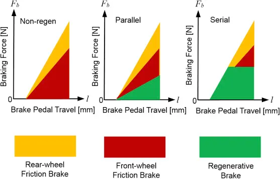
series control strategy : The series thermostat control strategy uses the generator and fuel converter to generate electrical energy for use by the vehicle.
The series thermostat control strategy uses the fuel converter as follows:
- To maintain charge in the battery, the fuel converter turns on when the SOC reaches the low limit, cs_lo_soc.
- The fuel converter turns off when the SOC reaches the high limit, cs_hi_soc.
- The fuel converter operates at the most efficient speed and torque level.
brief working of electric driven intelligent brake system :
EVs and hybrid vehicles use regenerative braking, which utilizes the motor to convert the kinetic energy during deceleration into electrical energy. With energy regeneration, an EV is able to run on less electricity and a hybrid vehicle on less fuel.
The EDIB (Electric Driven Intelligent Brake) allows and controls optimization of the regenerative brake and regular friction brake (hydraulic brake)
fter stepping on the brake pedal, the system produces natural and adequate braking force that corresponds to the operation. The amount of energy regeneration also needs to be increased as much as possible.
EDIB (Electric Driven Intelligent Brake) controls the regenerative brake and friction brake to support both of these requirements. Further, it also controls the reactive force from the pedal in order to unify the feeling when stepping down on the pedal and the sense of deceleration
When the driver steps on the brake pedal, the stroke sensor detects operation of the brake. That information is communicated to the ECU and controls the motor. The motor engages the piston and amplifies the friction brake's pressure (hydraulic pressure). Through optimum control of the friction brake's hydraulic pressure, the energy regeneration outcome is maximized.
AIM 3 : Make a MATLAB program which plots contour of given motor speed, torque and efficiency values. Attach the code as a .m file attach a screenshot of all the plots.
% Torque array
T =linspace(0,300);

%loss coefficients
kc = 0.18; %copper losses
ki = 0.006; %iron losses
kw = 0.000015; % windage losses

%Meshgrid
[X,Y] = meshgrid(w,T);
copper_loss = (Y.^2)*kc;
iron_loss = X*ki;
windage_loss = (X.^3)*kw;
K = 20;
output_power = X.*Y;
input_power = (copper_loss)+(iron_loss)+(windage_loss)+(output_power)+K;
Eff = (output_power)./(iput_power);
n = linspace(0.7,0.95,10);
contourf(X,Y,Eff,n);
title('Speed torque characterstics')
xlabel('Speed rad/s')
ylabel('Torque N-m')
Plot Results :
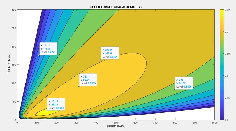
From the output graph you could see that the only at a particular speed and torque the efficiency is at maximum i.e. 95%
From the output graph you could see that the only at a particular speed and torque the efficiency is at maximum i.e. 95%
Where speed x = 151rad/sec at 24N-m Torque. As the speed increases the efficiencies of the motor will be reduced
Where speed x = 151rad/sec at 24N-m Torque. As the speed increases the efficiencies of the motor will be reduced