Week-11 Challenge: Braking
1.Calculation of Braking Energy:-
Braking Energy:-
When a force is applied to the brakes of a vehicle, there is work done on the friction between the brakes and the wheel. This reduces the kinetic energy of the vehicle, slowing it down and causing the temperature of the brakes to increase.
So in braking of vehicles, braking energy is nothing but kinetic energy.
K.E = `1/2(mv^2)`
Breaking Energy = `1/2*m*(Vf-Vi)^2`
where m=Mass of the vehicle
Vf=Final velocity of vehicle that is after brake is applied.
Vi=Inital velocity of vehicle that is before brake is applied.
Consider the driving cycle,
EPA Inspection and Maintenance (IM) 240 (Light-Duty)
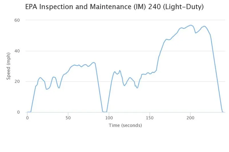
Link for the data of the EPA Inspection and Maintenance (IM) 240 (Light-Duty) drivecycle is :- https://drive.google.com/file/d/1QcTdv5qugYGi9cerK9rnM9UWZi-MjsH4/view?usp=sharing
Let the mass of the vehicle is 1000kg.
In above drive consider there are 2 stops at 90sec and 230secs.
(i) At 30mph
30mph=13.41mps
B.E= `1/2*1000(0-13)^2` =`500(-13.41)^2` =`500*(-179.82)` = 89914J = 89.9K`
(ii) At 50mph
50mph=22.35mps
B.E= `1/2*1000(0-22.35)^2`=`500(-22.35)^2`=`500*(-499.52)`=249761J=249.7KJ`
Total Breaking energy is sum of all energies 89.9KJ+249.7KJ=339.6KJ.
For above cycle total breaking energy is 339.6KJ.
2.
Why electric motor can’t develop braking torque at high speed similar to starting?
That’s due to what is called back EMF. The motor starts generating a voltage in reverse which acts against the supply voltage. Thus the current flow is reduced which, in turn, reduces the strength of the magnetic field which provides the turning torque.
It’s an inherent feature of any wound motor.The sort found in EVs has very complex power controllers which will do things like limit current to avoid burning out motors. For instance, the current at low RPM is likely to be limited to avoid burning out the coils. Up to a certain RPM the controller might be able to maintain the current level and thus torque. However, at a certain point the back EMF will be too high to be fully compensated for and then torque will start to fall away with higher RPM.
Hence a simple chart of maximum power and torque vs RPM might look like this :-
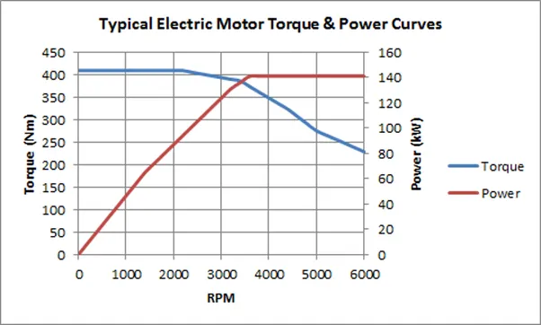
In practice, power will start to drop off too as that back EMF effect becomes more significant. There are ways round this by using a gearbox, but one of the advantages of EVs is avoiding the need for such a device in the power train.
How electric and mechanical brakes are coordinated?
In order to recover this heat energy and use it, regenerative braking uses the motor as a generator to convert the lost kinetic energy into the stored energy in the battery which can be used later. This helps the vehicle to use much of this stored energy from regenerative braking rather than using its own energy reserves.
REGENERATIVE BRAKING:
The regenerative braking is classified on the basis of control strategies into: -
- Serial regenerative braking
- Parallel regenerative braking
Serial regenerative braking:-
Serial regenerative braking is basically based on the combination of friction-based adjustable braking system that transfers energy to the electric motors and batteries under an integrated control strategy. The overall design of serial regenerative braking is to estimate the deceleration required and distribute the required braking force between the regenerative braking system and mechanical braking system. Serial braking system requires brake by wire system and has more consistent pedal feel due to good torque blending
capability. It can increase the efficiency by 15-30%.
Parallel regenerative braking:-
Parallel braking system is basically based on the combination of friction-based system and the regenerative
braking system, operated in tandem without an integrated control. The regenerative braking force is calculated from the brake control unit by comparing the requested brake torque and the motor torque available. Parallel regenerative braking system requires more work in achieving good torque blending. This system can increase the efficiency by 9-18%.
Electric Driven Intelligent Brake:-
After stepping on the brake pedal, the system produces natural and adequate braking force that corresponds to the operation. The amount of energy regeneration also needs to be increased as much as possible.
EDIB (Electric Driven Intelligent Brake) controls the regenerative brake and friction brake to support both of these requirements. Further, it also controls the reactive force from the pedal in order to unify the feeling when stepping down on the pedal and the sense of deceleration.
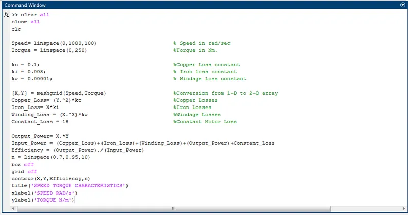
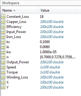
- Firstly, Speed and Torque range is given using linspace.
- Then, motor constant values are assigned namely Copper loss, Iron loss, Windage loss and Constant motor.
- 1-D is converted to 2-D using Meshgrid.
- All the losses are calculated and input power also calculated.
- Output Power is calculated by the product of speed and torque.
- Calculation of output power divided by input power gives the efficiency is done.
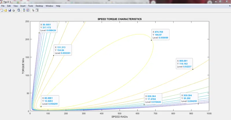
- Contour graph is plotted between Speed, Torque, Efficiency and n.
- Title and x and y axes labels are given.
Contour Plot:-
Conclusion:-
From the above plot we can conclude that from the given data
The maximum efficiency is 95% achieved at 676rad/sec and 196.9Nm.
The minimum efficiency is 69.4% achieved at 939rad/sec and 20Nm.