Week-11 Challenge: Braking
OBJECTIVE 1: DEFINE DRIVING CYCLE AND ENERGY CALCULATION FOR BRAKING
SOLUTION : A driving cycle is a series of data points representing the speed of vehicle versus time. Driving cycle are produced by different countries and organization to display the overall performance of vehicles in various ways like fuel consumption, state of charge for EV, pollution emission etc.
Here we consider the drive cycle data and use it to calculate the total energy required for braking mechanism.
Energy is given by :-
E = 1/2 (mv^2)
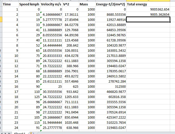
Result
From attached excel we can observe that toatal energy required for braking during particular drive cycle is = 9005.36KJ
OBJECTIVE 2: WHY ELECTRIC MOTOR CANT DEVELOP BRAKING TORQUE AT HIGH SPEED SIMILAR TO STARTING & HOW ELECTRIC AND MECHANICAL BRAKES ARE COORDINATED
SOLUTION : Electric Motor have a tendency to produce high torque at the low speed or starting condition and low torque at high speed.
- Starting Torque can be considered as the situation when vehicle is initially at rest or at low speed in that case torque produced by motor is generally high.
- In braking stage, the speed of motor is high sometimes greater then synchronous speed and due to such high value braking torque will be low or less effective as compared to low speed condition as when motor will be at low speed it will be having more torque to support the braking operaton. During high speed torque demanded is high so less torque will be available for braking operation at high speed.
- Kinetic energy or momentum - kinetic energy of a slow moving car is much less then that of a car travelling at high speed. Since the braking operation is directly proportional to the kinetic energy braking becomes tough at high speed as compared to low speed.
ELECTRIC AND MECHANICAL BRAKES COORDINATION :-
Since the electric motor cannot generate enough braking torque to stop vehicles at high speed, Hence mechanical brakes are used in the larger proportion from stopping mechenism. Braking control strategy can be explained in 2 parts i.e.
- Series Braking :- In this mechenical brake and regenrative brake are applied one after another. For slow braking process regenerative braking comes into play followed by mechenical brakes while ifimmediate braking is required mechenical brakes initially will come into action.
- Parallel Braking :- In this both brakes are applied simultaneously. In this regenrative braking is possible at high speed torque as it is overcome by mechanical braking.
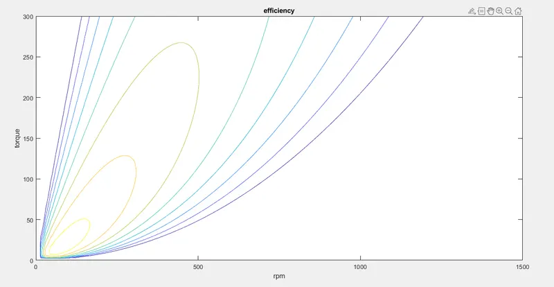
OBJECTIVE 3 : PLOT A CONTOUR GRAPH FOR MOTOR TORQUE, SPEED & EFFICIENCY
SOLUTION : CODE for plotting contour graph is given as
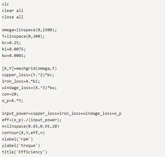
- Here arrays are formed for rotational speed and torque using linspace command.
- In motor there are 4 types of losses :-
- Copper losses(kc) =are produced as the result of armature resistance, T proportional to I =kc*T^2
- Iron losses (ki)= change according to speed as speed is changed back emf of different values are generated (magnetic field effect)= ki*w
- Windage losses= due to size and shape of motor
- Other losses are in constant
- A mesh grd is formed with X as rotational speed & Y as torque.
- Output Power at all these points (x,y) is found by T*W
- Total losses is the sum of all above losses
- To form the cotour different values are assigned for efficiency.Here V which contains the efficiency values are plotted on w-T plane.