Braking of vehicle using electric motor
Objective-1:
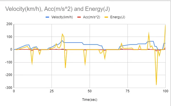
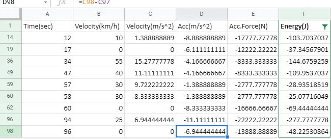
For a defined driving cycle, calculate the energy required for braking.
Ans:
Drive cycle link:https://docs.google.com/spreadsheets/d/1YAi9wiEHeUFySeOFil1CLWCWWv-yVfJ_IpvYoIZPxJI/edit?usp=sharing
The energy required for braking excel file link:https://docs.google.com/spreadsheets/d/1Xdvlpocy7PtM57FdvOClWqkXiI2h0gxk4YbdKTQnnhI/edit?usp=sharing
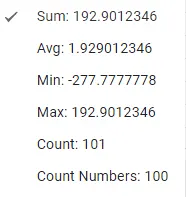
This is the calculation for a total of 100 values in the drive cycle:
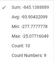
This is the deacceleration sum and average values for the particular drive cycle:
----------------------------------------------------------------------------------------------------------------------------------------------------------------
Objective-2:
Why electric motor can’t develop braking torque at a high speed similar to starting? How electric and mechanical brakes are coordinated?
Ans:
A situation does not occur at the beginning of acceleration because most of the torque is used to increase the kinetical energy of the load (and motor). But when the speed is already high and no extra load is applied it is not possible to increase the torque.
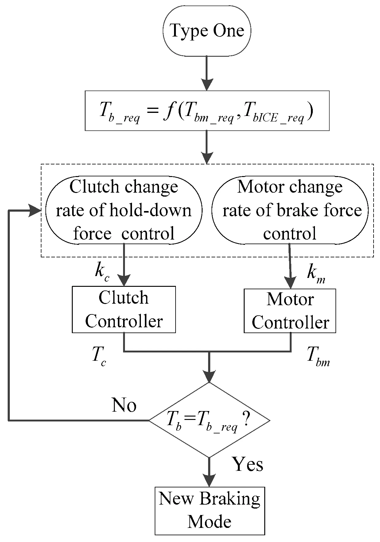
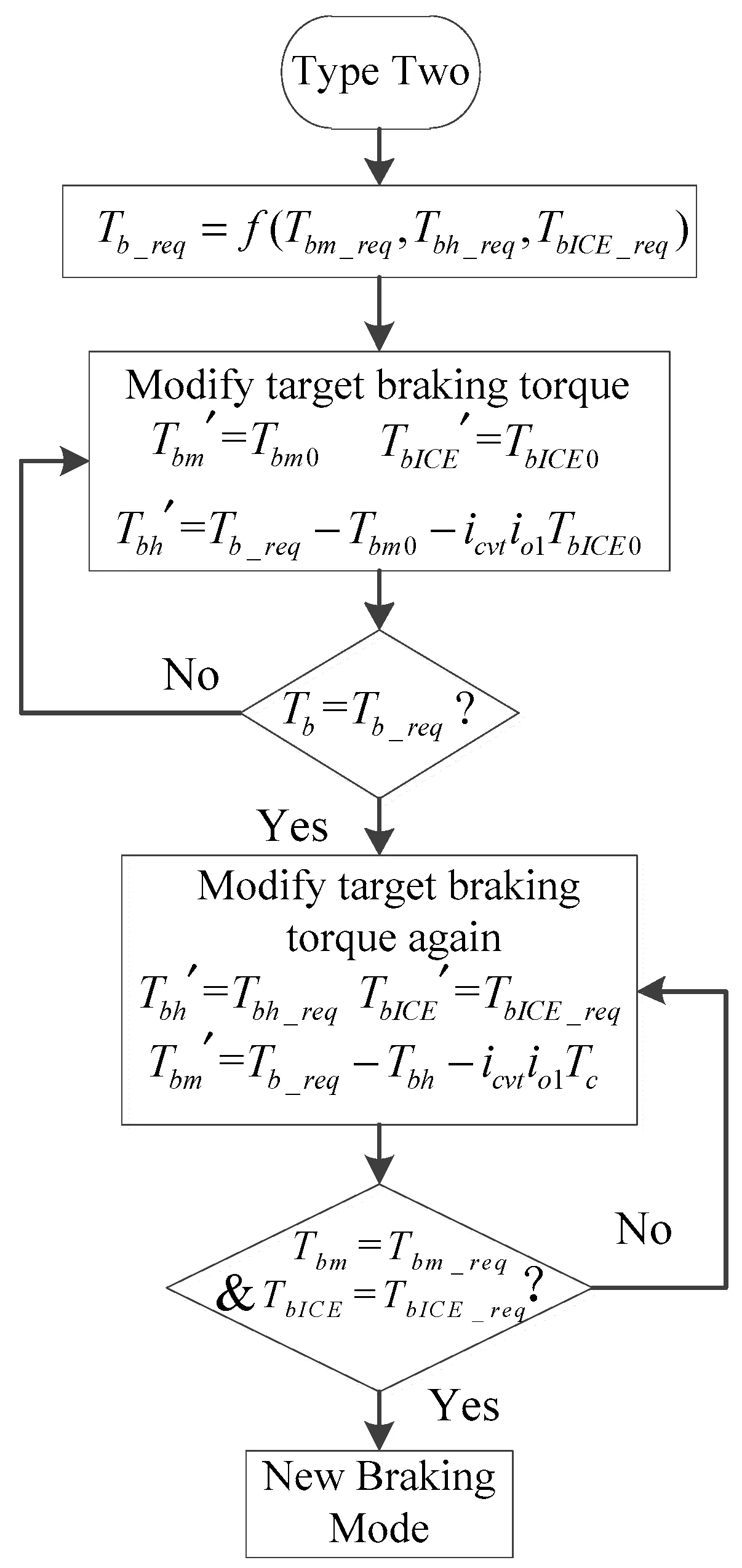
According to the braking force distribution control strategy, there are four main braking modes: pure electric braking mode, motor and engine braking mode, motor and hydraulic braking mode, and hydraulic braking mode. Based on the kinetics analysis of the braking mode, there are three types of braking torque that need to be coordinated during braking mode switching. The motor, the hydraulic, and the engine braking systems are three different systems with different dynamic response characteristics; therefore, the sequences and moments of the three joint systems are different. Because mode switching is completed instantaneously, the braking torque varies sharply during the intervention and exit from braking. If there is no coordinated control, it will cause torque fluctuation and seriously worsen the ride comfort of the vehicle.
--------------------------------------------------------------------------------------------------------------------------------------------------------------------
Objective-3:
Make a MATLAB program that plots the contour of given motor speed, torque and efficiency values. Attach the code as a .m file attach a screenshot of all the plots.
Matlab script:
%inputs for x and y axis, speed and torque respectively
%speed in rad/sec
x = linspace(1,1000);
%torque T in N-m
y = linspace(1,250);
%motor losses constants
kc = 0.2;  %copper losses
ki = 0.008;  %iron losses
kw = 0.00001;  %windage losses
conL = 20;   %motor losses
%creating mesh
[X,Y] = meshgrid(x,y);
outputpower = (X.*Y);       %power output
B = (Y.^2)*kc;              %copper losses
C = X*ki;                   %iron losses
D = (X.^3)*kw;              %windage losses
inputpower= outputpower+B+C+D+conL;
Z = outputpower./inputpower;

%efficiences for countour
V = [0.70,0.75,0.80,0.83,0.85,0.90,0.91,0.92,0.93,0.95];
box off
grid off
contour(X,Y,Z,V,'showtext','on')
xlabel('speed rad/sec')
ylabel('Torque N-m')
hold on
v = [8000,10000];
contour(X,Y,outputpower,v)
Explanation:
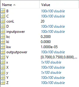
- In this script, initially, we gave the x and y-axis parameters using the linspace command.
- Considered all the losses in the motors happening while running.
- Created the mesh grid and calculated the input power with the input values and finally calculated the efficiencies of the motor.
- Plotted the contour plot for the efficiencies calculated and used the contour command.
Output:
Result:
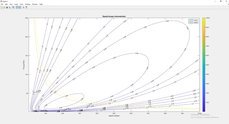
- Here we can observe that all contours are a group of efficiencies
- Innermost contour is the highest efficiencies amongst all as the height is maximum as the height decreases the efficiencies also decreases.
- Here two yellow lines represent the power output lines between 8kW and 5kW.
-------------------------------------------------------------------------------------------------------------------------------------------------------------------
Conclusion:
- Calculated the total energy required for braking for a particular drive cycle.
- Explained why electric motor can't obtaining high braking torque at high speed and also the actuation of the mechanical and motor brake.
- Plotted the contour for speed, torque and efficiencies of the motor.