Week-11 Challenge: Braking
BRAKING
AIM:
- To defined driving cycle, calculate the energy required for braking.
- Why electric motor can’t develop braking torque at high speed similar to starting? How electric and mechanical brakes are coordinated?
- To Make a MATLAB program which plots contour of given motor speed, torque and efficiency values. Attach the code as a .m file attach a screenshot of all the plots.
STUDY-1:
To Defined driving cycle, calculate the energy required for braking.
A driving cycle is a series of data points representing the speed of a vehicle versus time. Driving cycles are produced by different countries and organizations to assess the performance of vehicles in various ways, as for instance fuel consumption, electric vehicle autonomy and polluting emissions.
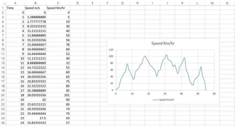
As we assume the values of time and speed we have created a graph in excel.
DRIVE CYCLE:
The Kinetic Energy E of a vehicle is given by the formula
`E = 1/2mv^2`
m = mass of the vehicle
v = velocity of the vehicle
If the vehicle speed decreasesfrom Intial velocity `Vi` to final velocity `Vf` the the required braking energy is given by the formula
`B E =1/2 m(Vi-Vf)^2`
BE = Braking Energy
MATLAB CODE:
%Mass of the Vehicle in Kg
m = 1000;
% Time of the period
t = DRIVECYCLE(:,1);

% Velocity data
v = DRIVECYCLE(:,2);

B = zeros(1,56);

for i= 1:55
    if v(i)>v(i+1)
        % B stands for brake energy
        B(i) = 0.5*m*(v(i)-v(i+1))^2;
    end

end
fprintf('Total break energy is %d',sum(B))
fprintf('Average brake energy is %d',mean(B))

%plotting the results
figure(1)
subplot(2,1,1)
plot(t,v)
xlabel('Time(s)')
ylabel('Velocity(m/s)')
title('DRIVE CYCLE')

subplot(2,1,2)
plot(t,B)
xlabel('Time(s)')
ylabel('Energy')
title('BRAKING ENERGY')
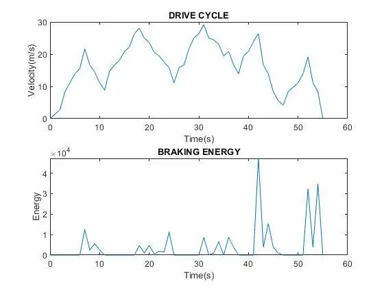
RESULT:
STUDY-2:
Electric motor can’t develop braking torque at high speed similar to starting:
Sometimes after accelerating you can't reach the maximum torque. The reason is that no matter how much the current loop wants to increase current (proportional to torque) by increasing the PWM duty cycle of the power stage, the Vmotor is too close to Vbemf and therefore current can't increase more.Whenever Friction torque + Additional loads = Motor Torque, the load remain in equilibrium (does not move, or moves under constant speed). Whenever Friction torque + Additional loads < Motor Torque, the load accelerates (Motor torque - Friction torque - Additional loads = Acceleration torque > 0). Al high speeds, the BEMF is so close to Vbus that the applicable Motor torque gets limited. Then, the bigger the Friction torque + Additional load is, the smaller the Acceleration torque becomes. This can also occur if acceleration or speed is limited by some reason.
This situation does not occur at the beginning of an acceleration because most of the torque is used to increase the kinetical energy of the load (and motor). But when the speed is already high and no extra load is applied it is not possible to increase the torque.
Reasons why the torque actual is NOT the real torque:
- If commutation, phasing, is not correct, an important part of the current is not useful torque, it just creates electrical and magnetic loses.
- If current loop is not well configured or unstable, the current will be higher and with ripple, the real "useful mechanical torque" will be indeed lower.
- Torque constant can vary due to several factors, like motor construction, temperature of the magnets (that affects its magnetic properties).
How to prevent is,
- Increase DC bus voltage.
- Unlimit system acceleration.
- Use a motor with less resistance and lower back EMF proportion.
The term braking comes from the term brake. We know that brake is an equipment to reduce the speed of any moving or rotating equipment, like vehicles, locomotives. The process of applying brakes can be termed as braking. Now coming to the term or question what is braking. First of all we can classify the term braking in two parts
- Mechanical Braking
- Electrical Braking
Electrical Braking:
Brakes are used to reduce or cease the speed of motors. We know that there are various types of motors available (DC motors, induction motors, synchronous motors, single phase motors etc.) and the specialty and properties of these motors are different from each other, hence this braking methods also differs from each other. But we can divide braking in to three parts mainly, which are applicable for almost every type of motors.
- Regenerative Braking.
- Plugging type braking.
- Dynamic braking.
Regenerative Braking:
Regenerative braking takes place whenever the speed of the motor exceeds the synchronous speed. This baking method is called regenerative braking because here the motor works as generator and supply itself is given power from the load, i.e. motors. The main criteria for regenerative braking is that the rotor has to rotate at a speed higher than synchronous speed, only then the motor will act as a generator and the direction of current flow through the circuit and direction of the torque reverses and braking takes place. The only disadvantage of this type of braking is that the motor has to run at super synchronous speed which may damage the motor mechanically and electrically, but regenerative braking can be done at sub synchronous speed if the variable frequency source is available.
Plugging Type Braking:
Another type of braking is Plugging type braking. In this method the terminals of supply are reversed, as a result the generator torque also reverses which resists the normal rotation of the motor and as a result the speed decreases. During plugging external resistance is also introduced into the circuit to limit the flowing current. The main disadvantage of this method is that here power is wasted.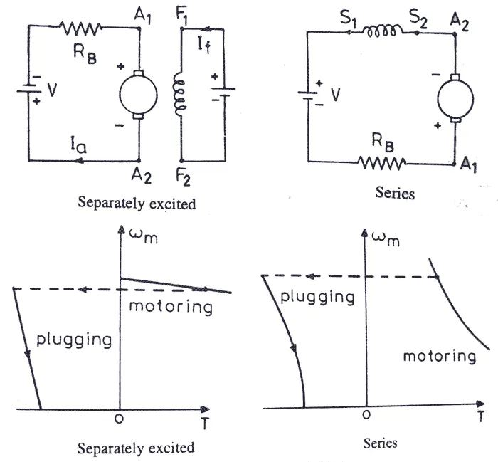
Dynamic Braking:
Another method of reversing the direction of torque and braking the motor is dynamic braking. In this method of braking the motor which is at a running condition is disconnected from the source and connected across a resistance. When the motor is disconnected from the source, the rotor keeps rotating due to inertia and it works as a self-excited generator. When the motor waorks as a generator the flow of the current and torque reverses. During braking to maintain the steady torque sectional resistances are cut out one by one.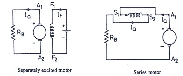
Mechanical braking system:
The mechanical braking system powers the hand brake or emergency brake. It is the type of braking system in which the brake force applied on the brake pedal is carried to the final brake drum or disc rotor by the various mechanical linkages like cylindrical rods, fulcrums, springs etc. In order to stop the vehicle. Mechanical brakes were used in several old automobile vehicles but they are archaic nowadays due to their less effectiveness.
Types of Brakes:
Disc Brake:
The disc brake is a mechanism for slowing or stopping the rotation of a wheel from its motion. A disc brake is normally made of cast iron, but in some cases, it is also made of composites such as carbon-carbon or ceramic -matrix composites. This is linked to the wheel and/or the axle. To stop the wheel, friction material in the form of brake pads is forced against both sides of the disc. Friction caused, on the disc wheel will slow or stop.
Drum Brake:
A drum brake is a traditional break in which the friction is caused by a set of shoes or pads that press against a rotating drum-shaped part called a brake drum.
The term \"drum brake\" usually means a brake in which shoes press on the inner surface of the drum. Where the drum is pinched between two shoes, similar to a standard disk brake , it is sometimes called a \"pinch drum brake\", although such brakes are relatively rare.
clear all
close all
clc

W = linspace(0,5000);
T = linspace(0,1000);

% motor constants
Kc = 0.3; % for copper loss
Ki = 0.009; % for iron loss
Kw = 0.00001; % for windage loss
cont = 25; % for constant motor losses

% making mesh
[X,Y] = meshgrid(W,T);
outputpower = (X.*Y); %Torque*Speed = Power
B = (Y.^2)*Kc; % copper loss
C = (X.^3)*Kw; % winding loss
D = X*Ki; % Iron loss
Inputpower = outputpower + B + C + D + cont;
Z = outputpower./Inputpower;

% set the efficiencies for which the control will be plotted
V = [0.72,0.74,0.75,0.80,0.82,0.87,0.89,0.90,0.92];
box off
grid off
contour(X,Y,Z,V)
xlabel('Speed(rad/s)')
ylabel('Torque(N.m)')
hold on
V = [8000,10000];
contour(X,Y.outoutpower,V)
RESULT:
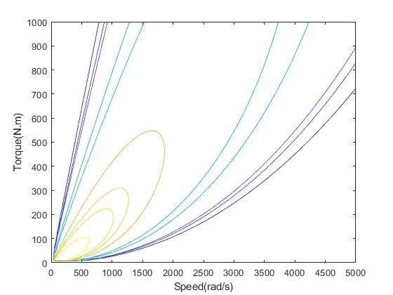
From this contour plot, we can see that the higest level of efficiency arises in the innermost contour plot and this efficiency decreases as the contours increase in size from the innermost contour.
BRAKING
AIM:
- To defined driving cycle, calculate the energy required for braking.
- Why electric motor can’t develop braking torque at high speed similar to starting? How electric and mechanical brakes are coordinated?
- To Make a MATLAB program which plots contour of given motor speed, torque and efficiency values. Attach the code as a .m file attach a screenshot of all the plots.
STUDY-1:
To Defined driving cycle, calculate the energy required for braking.
A driving cycle is a series of data points representing the speed of a vehicle versus time. Driving cycles are produced by different countries and organizations to assess the performance of vehicles in various ways, as for instance fuel consumption, electric vehicle autonomy and polluting emissions.
As we assume the values of time and speed we have created a graph in excel.
DRIVE CYCLE:
The Kinetic Energy E of a vehicle is given by the formula
`E = 1/2mv^2`
m = mass of the vehicle
v = velocity of the vehicle
If the vehicle speed decreasesfrom Intial velocity `Vi` to final velocity `Vf` the the required braking energy is given by the formula
`B E =1/2 m(Vi-Vf)^2`
BE = Braking Energy
MATLAB CODE:
%Mass of the Vehicle in Kg
m = 1000;
% Time of the period
t = DRIVECYCLE(:,1);

% Velocity data
v = DRIVECYCLE(:,2);

B = zeros(1,56);

for i= 1:55
    if v(i)>v(i+1)
        % B stands for brake energy
        B(i) = 0.5*m*(v(i)-v(i+1))^2;
    end

end
fprintf('Total break energy is %d',sum(B))
fprintf('Average brake energy is %d',mean(B))

%plotting the results
figure(1)
subplot(2,1,1)
plot(t,v)
xlabel('Time(s)')
ylabel('Velocity(m/s)')
title('DRIVE CYCLE')

subplot(2,1,2)
plot(t,B)
xlabel('Time(s)')
ylabel('Energy')
title('BRAKING ENERGY')
RESULT:
STUDY-2:
Electric motor can’t develop braking torque at high speed similar to starting:
Sometimes after accelerating you can't reach the maximum torque. The reason is that no matter how much the current loop wants to increase current (proportional to torque) by increasing the PWM duty cycle of the power stage, the Vmotor is too close to Vbemf and therefore current can't increase more.Whenever Friction torque + Additional loads = Motor Torque, the load remain in equilibrium (does not move, or moves under constant speed). Whenever Friction torque + Additional loads < Motor Torque, the load accelerates (Motor torque - Friction torque - Additional loads = Acceleration torque > 0). Al high speeds, the BEMF is so close to Vbus that the applicable Motor torque gets limited. Then, the bigger the Friction torque + Additional load is, the smaller the Acceleration torque becomes. This can also occur if acceleration or speed is limited by some reason.
This situation does not occur at the beginning of an acceleration because most of the torque is used to increase the kinetical energy of the load (and motor). But when the speed is already high and no extra load is applied it is not possible to increase the torque.
Reasons why the torque actual is NOT the real torque:
- If commutation, phasing, is not correct, an important part of the current is not useful torque, it just creates electrical and magnetic loses.
- If current loop is not well configured or unstable, the current will be higher and with ripple, the real "useful mechanical torque" will be indeed lower.
- Torque constant can vary due to several factors, like motor construction, temperature of the magnets (that affects its magnetic properties).
How to prevent is,
- Increase DC bus voltage.
- Unlimit system acceleration.
- Use a motor with less resistance and lower back EMF proportion.
The term braking comes from the term brake. We know that brake is an equipment to reduce the speed of any moving or rotating equipment, like vehicles, locomotives. The process of applying brakes can be termed as braking. Now coming to the term or question what is braking. First of all we can classify the term braking in two parts
- Mechanical Braking
- Electrical Braking
Electrical Braking:
Brakes are used to reduce or cease the speed of motors. We know that there are various types of motors available (DC motors, induction motors, synchronous motors, single phase motors etc.) and the specialty and properties of these motors are different from each other, hence this braking methods also differs from each other. But we can divide braking in to three parts mainly, which are applicable for almost every type of motors.
- Regenerative Braking.
- Plugging type braking.
- Dynamic braking.
Regenerative Braking:
Regenerative braking takes place whenever the speed of the motor exceeds the synchronous speed. This baking method is called regenerative braking because here the motor works as generator and supply itself is given power from the load, i.e. motors. The main criteria for regenerative braking is that the rotor has to rotate at a speed higher than synchronous speed, only then the motor will act as a generator and the direction of current flow through the circuit and direction of the torque reverses and braking takes place. The only disadvantage of this type of braking is that the motor has to run at super synchronous speed which may damage the motor mechanically and electrically, but regenerative braking can be done at sub synchronous speed if the variable frequency source is available.
Plugging Type Braking:
Another type of braking is Plugging type braking. In this method the terminals of supply are reversed, as a result the generator torque also reverses which resists the normal rotation of the motor and as a result the speed decreases. During plugging external resistance is also introduced into the circuit to limit the flowing current. The main disadvantage of this method is that here power is wasted.
Dynamic Braking:
Another method of reversing the direction of torque and braking the motor is dynamic braking. In this method of braking the motor which is at a running condition is disconnected from the source and connected across a resistance. When the motor is disconnected from the source, the rotor keeps rotating due to inertia and it works as a self-excited generator. When the motor waorks as a generator the flow of the current and torque reverses. During braking to maintain the steady torque sectional resistances are cut out one by one.
Mechanical braking system:
The mechanical braking system powers the hand brake or emergency brake. It is the type of braking system in which the brake force applied on the brake pedal is carried to the final brake drum or disc rotor by the various mechanical linkages like cylindrical rods, fulcrums, springs etc. In order to stop the vehicle. Mechanical brakes were used in several old automobile vehicles but they are archaic nowadays due to their less effectiveness.
Types of Brakes:
Disc Brake:
The disc brake is a mechanism for slowing or stopping the rotation of a wheel from its motion. A disc brake is normally made of cast iron, but in some cases, it is also made of composites such as carbon-carbon or ceramic -matrix composites. This is linked to the wheel and/or the axle. To stop the wheel, friction material in the form of brake pads is forced against both sides of the disc. Friction caused, on the disc wheel will slow or stop.
Drum Brake:
A drum brake is a traditional break in which the friction is caused by a set of shoes or pads that press against a rotating drum-shaped part called a brake drum.
The term \"drum brake\" usually means a brake in which shoes press on the inner surface of the drum. Where the drum is pinched between two shoes, similar to a standard disk brake , it is sometimes called a \"pinch drum brake\", although such brakes are relatively rare.
clear all
close all
clc

W = linspace(0,5000);
T = linspace(0,1000);

% motor constants
Kc = 0.3; % for copper loss
Ki = 0.009; % for iron loss
Kw = 0.00001; % for windage loss
cont = 25; % for constant motor losses

% making mesh
[X,Y] = meshgrid(W,T);
outputpower = (X.*Y); %Torque*Speed = Power
B = (Y.^2)*Kc; % copper loss
C = (X.^3)*Kw; % winding loss
D = X*Ki; % Iron loss
Inputpower = outputpower + B + C + D + cont;
Z = outputpower./Inputpower;

% set the efficiencies for which the control will be plotted
V = [0.72,0.74,0.75,0.80,0.82,0.87,0.89,0.90,0.92];
box off
grid off
contour(X,Y,Z,V)
xlabel('Speed(rad/s)')
ylabel('Torque(N.m)')
hold on
V = [8000,10000];
contour(X,Y.outoutpower,V)
RESULT:
From this contour plot, we can see that the higest level of efficiency arises in the innermost contour plot and this efficiency decreases as the contours increase in size from the innermost contour.