Week-11 Challenge: Braking
1.For a defined driving cycle, calculate the energy required for braking.
The braking performance is one of the most important concerns in vehicle safety. In urban area driving, a significant amount of energy is consumed in braking. Electrification of vehicles makes it feasible to recover some of the energy lost in braking. A hybrid braking system was developed to ensure the efficient braking of the vehicle and recovering the braking energy. The design and control objectives of such a hybrid braking system are to ensure sufficient braking force to quickly reduce the vehicle speed, properly distributing the brake force to the front and rear axle, and also recover as much braking energy as possible. So understanding of braking energy of a driving cycle is important.
GOVERNING EQUATION:
Braking Energy = `1/2*m.(v_i-v_f)^2 ------ J`
Where,
m - Mass of the vehicle (kg)
v - Velocity of vehicle (m/s)
sample drive cycle:
a simple ECE-15 drive cycle is taken and braking energy is calculated
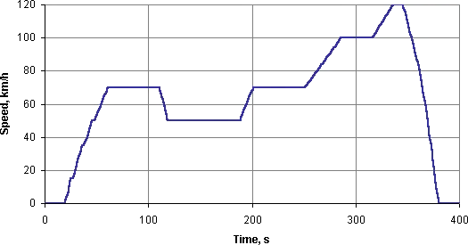
the parameters in the drive cycle is shown in the below image
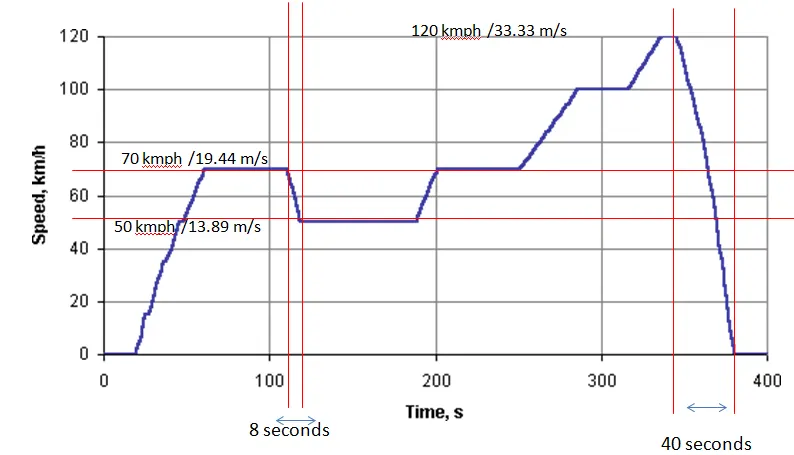
the braking regions are highlighted in the below image
lets take a vehicle of mass 1000kg.
1. vehicle decelerates from 70 kmph to 50 kmph in 8 seconds
so braking energy=`1/2*m.(v_i-v_f)^2 ------ J`
=0.5*1000(19.44-13.89)^2 = 500(5.5^2)=15401
braking energy1 = 15.401 kJ
2. vehicle decelerates from 120 kmph to 0 kmph in 40 seconds
so braking energy=`1/2*m.(v_i-v_f)^2 ------ J`
=0.5*1000(33.33-0)^2 = 500(5.5^2)=555445
braking energy2 = 555.45 kJ
total braking energy is 570.85 kJ or 0.1585 kWh
--------------------------------------------------------------------------------------------------------------------------------------------
2.Why electric motor can’t develop braking torque at a high speed similar to starting? How electric and mechanical brakes are coordinated?
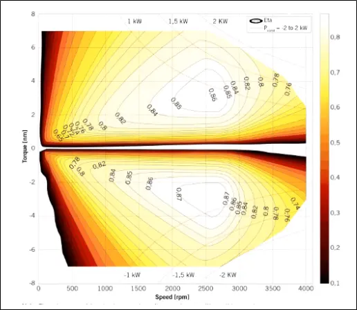
The figure represents forward motoring (positive torque and speed) and forward braking (negative torque and positive speed).
We know that torque of the induction motor is inversely proportional to the square of the rotor speed. So at higher speed, the torque will be less. That’s why a high-speed electric motor cannot produce braking torque similar to starting.
How electric and mechanical brakes are coordinated?
The electric motor must be controlled to produce the proper amount of braking force to recover as much braking energy as possible and at the same time, the total braking force must be sufficient to meet vehicle deceleration commanded by the driver. For meeting sufficient braking in EV vehicles we use brake control strategies.
Series brake control: Here mechanical brake and the electric brake is done one after another.
Parallel brake control: Here both brakes are applied simultaneously.
We need both mechanical and electrical braking systems. In emergency braking or parking brake, we needed mechanical braking.
Mechanical brake: It is nothing but friction brakes used in a vehicle to slow down the vehicle. The most common type of brakes is drum brake and disc brake.
Electrical braking: It is used to reduce the speed of the motor depending upon the flux and torque. This kind of braking can be done in different methods.
- Plugging type braking
- Dynamic braking
- Regenerative braking
--------------------------------------------------------------------------------------------------------------------------------------------
3.Make a MATLAB program that plots the contour of given motor speed, torque, and efficiency values. Attach the code as a .m file attach a screenshot of all the plots.
Power= Speed*Torque
Copper loss, `c_u=k_c*T^2`
Iron loss, `I=k_i*omega`
Windage loss, `W=k_w*w^3`
Constant/conduction losses, C
Where,
ω – Speed (rad/s)
T – Torque (Nm)
`k_c`-Constant for copper loss
`k_i`- Constant for iron loss
`k_w`- Constant for windage loss
Matlab code:
clc
clear all
close all
%Program for efficiency contour plot
s=linspace(0,1000,250); %Motor Speed(rad/sec)
t=linspace(0,250,250); %Torque(Nm)

kc=0.3; %Copper loss constant
ki=0.009; %Iron loss constant
kw=0.00001; %Windage loss constant
c=30; %Constant/ conduction loss

[x,y]=meshgrid(s,t);
output_power= (x.*y); %Power = speed * torque
cu=kc.*(y.^2); %Copper loss= kc*torque^2
I=ki.*x; %Iron loss= speed*ki
w=kw.*(x.^3); %Windage loss= kw*speed^3

input_power=output_power+cu+I+w+c; %Input power= Output power+Losses
z=output_power./input_power; %Efficiency


%Mapping of efficiency point
v=[0.50,0.55,0.60,0.65,0.70,0.75,0.80,0.84,0.90,0.95];
contour(x,y,z,v)
grid off;
xlabel('Speed in rad/s');
ylabel('Torque in N.m');
RESULT:
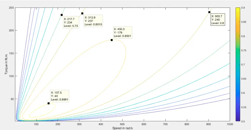
From the contour, we can see that efficiency is maximum at lower speeds and low torque(loads).
for better efficiency, the motor has to operate in the yellow and orange circular contour regions.