Week-11 Challenge: Braking
MOTOR BRAKING AND EFFICIENCY
AIM :
- For a defined driving cycle, calculate the energy required for braking.
- Why electric motor can’t develop braking torque at high speed similar to starting? How electric and mechanical brakes are coordinated?
- Make a MATLAB program which plots contour of given motor speed, torque and efficiency values. Attach the code as a .m file attach a screenshot of all the plots.
QUESTION 1:
EXPLAINATION :
DRIVING CYCLE :
A driving cycle is a series of data points representing the speed of a vehicle versus time. Driving cycles are produced by different countries and organizations to assess the performance of vehicles in various ways, as for instance fuel consumption, electric vehicle autonomy and polluting emissions.
Based on different places and the road conditions always a driving cycle will be made and there are different driving cycles according to the places accross the world.
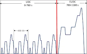
Another use for driving cycles is in vehicle simulations. More specifically, they are used in propulsion system simulations to predict performance of internal combustion engines, transmissions, electric drive systems, batteries, fuel cell systems, and similar components.
The above shown images are some of the driving cycles which are according to urban drive cycle and extra urban drive cycle and in another right side one the drive cycle is showing the distance travelled, speed, decceleration, acceleration.
BRAKING :
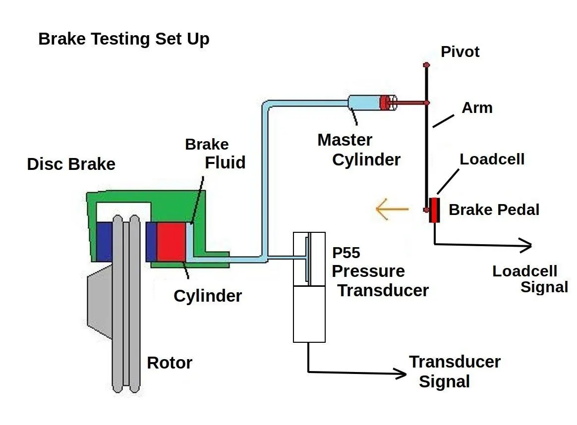
A brake is a mechancal device that inhibits motion by absorbing energy from a moving system. It is used for slowing or stopping a moving vehicle, wheel, axle, or to prevent its motion, most often accomplished by means of friction.
Most brakes commonly use friction between two surfaces pressed together to convert the kinetic of the moving object into heat, though other methods of energy conversion may be employed. For example, regenerative braking converts much of the energy to electrical braking, which may be stored for later use. Other methods convert kinetic energy into potential energy in such stored forms as unpressurized or pressurized oil.
DRIVE CYCLE vs BRAKING ENERGY:
So if we consider a drive cycle there exists braking varying with along the drive cycle to decrease the speed of the vehicle.
Now we are going to see the braking when a vehicle suddenly decreases its speed from high speed to low speed.
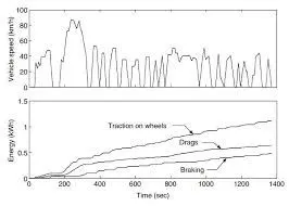
So as a part of drive cycle we can see the braking energy required for a decrease in the speed in a particular drive cycle.
Over all we can say that :
Traction on wheels = drag + braking
Now by considering some of the values of a drive cycle and we can calculate the braking energy for about three tests.
So by a Excel sheet we can calculate the braking energy which is required for deccerelate the vehicle from a high speed to the low speed.
Braking energy calculation expression :
Braking energy = 0.5*M*(Vi-Vf)^2
here :
M = total mass of the vehicle+payload mass
Vi = Initial velocity at which vehicle starts its decceleration.
Vf = The final Velocity of vehicle after decceleration.
Below is the link for excel sheet where calculation of braking energy is done :
- In the first condition When the vehicle is deccelerating from the 60 KMPH to 0 KMPH in 10 sec the required braking energy is 208.333 KJ.
- In the second condition the vehicle is deccelerated from the speed of 80 KMPH to 0 KMPH in 10 sec and the braking energy required is 370.370 KJ.
- In the third condition the vehicle is deccelerated from the speed of 100 KMPH to 0 KMPH in 10 sec and the braking energy required is 578.703 KJ.
Therefore from the above results we can conclude that when ever the braking is done from high speed to low speed the braking energy required is more.
QUESTION 2 :
Why electric motor can’t develop braking torque at high speed similar to starting? How electric and mechanical brakes are coordinated?
EXPLAINATION :
Electric motor cannot develop the same torque as the torque developed while starting of the motor because the torque which is developd while braking will be in negative direction and this torque cannot be equal to the starting torque and aslo the same power required for braking cannot be produced by braking and fed to the battery.
ELECTRICAL BRAKING :
If the load is removed from an electric motor and supply to it be disconnected, it will continue to run for some time due to inertia. The time elapsing before it stops will be especially long if the motor is massive and has run at high speed.
It is essential, however, in many cases that the motor and its driven machine be stopped quickly (in machine tools, cranes, hoists etc). In fact, quick stopping of a motor is more essential than quick starting. Delay in starting up a motor only causes the machinery to stand idle; a delay in stopping a motor may result in heavy damage to equipment or to the manufactured products and even the loss of human life.
Based on the purpose for which braking is employed, it is of the two types, viz, braking while bringing the drive to rest and braking while lowering loads. In the first type, the device employed for braking absorbs the kinetic energy of the moving parts while in the second one, it absorbs, in addition to the kinetic energy, potential energy, usually gravitational which can drive the system at an excessively high speed.
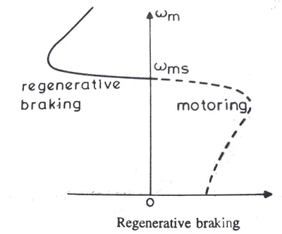
Braking, while stopping, may be used for any one of the following objectives:
(i) Reducing the time taken to stop.
(ii) Stopping exactly at specified points, for example in lifts; sometimes such precise stops are necessary for reasons of safety.
(iii) Feeding back, atleast a portion of the power, to the supply system.
Braking, while lowering loads, may be employed for any of the following purposes:
(i) Controlling the speed at which the load comes down and limiting it to a safe value.
(ii) Feeding power back to the supply system.
MECHANICAL BRAKING :
Mechanical brakes all act by generating frictional forces as two surfaces rub against each other. The stopping power or capacity of a brake depends largely on the surface area of frictional surfaces as well as on the actuation force applied. The friction and wear encountered by the working surfaces are severe. Thus, the durability of a brake or service life between maintenance depends heavily on the type of material used to line the shoe or pad.
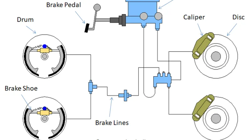
Mechanical brakes are assemblies consisting of mechanical elements for the slowing or stopping of shafts in equipment drives. They use levers or linkages to transmit force from one point to another. Braking slows or stops the movement of the coupled shafts. There are several types of mechanical brakes. Band brakes, the simplest brake configuration, have a metal band lined with heat and wear resistant friction material. Drum brakes, which are commonly used on automobile rear wheels, work when shoes press against a spinning surface called a drum. Disc brakes are constructed of brake pads, a caliper, and a rotor. During operation, the brake pads are squeezed against the rotor. Cone brakes are made with a cup and a cone, which is lined with heat and wear resistant material. During actuation, the cone is pressed against the mating cup surface.
DISC BRAKING :
The disc brake is a device for slowing or stopping the rotation of a wheel while it is in motion. A brake disc is usually made of cast iron , but may in some cases be made of composites such as reinforced carbon-carbon or ceramic -matrix composites. This is connected to the wheel and/or the axle . To stop the wheel, friction material in the form of brake pads (mounted on a device called a brake caliper ) is forced hydraulically , pneumatically or electromagnetically against both sides of the disc. Friction causes the disc and attached wheel to slow or stop. Brakes convert motion to heat, and if the brakes get too hot, they become less effective, a phenomenon known as brake fade .
DRUM BRAKING :
A drum brake is a brake in which the friction is caused by a set of shoes or pads that press againt a rotating drum-shaped part called a brake drum.
The term "drum brake" usually means a brake in which shoes press on the inner surface of the drum. When shoes press on the outside of the drum, it is usually called a clasp brake . Where the drum is pinched between two shoes, similar to a conventional disk brake , it is sometimes called a "pinch drum brake", although such brakes are relatively rare. A related type of brake uses a flexible belt or "band" wrapping around the outside of a drum, called a band brake .
EXHAUST BRAKING :
An exhaust brake works by restricting the flow of exhaust gases through the engine Heavy goods vehicles can often require increased braking, in situations where friction brakes could overheat and fail. This is achieved by using an exhaust brake. It achieves this by closing a butterfly valve located in the exhaust manifold. This maintains high pressures in the exhaust manifold, and the engine cylinders, which in turn, acts as a brake against the engine rotating. This then slows the road wheels through the transmission, or power train.
ELECTRICAL AND MECHANICAL BRAKES CORODINATION :
The coordination of these mechanical and electrical brakes are classified into two types :
- Series braking
- Parallel braking
SERIES BRAKING :
In these type of braking of electrical vehicle the both brakes are applied one after another as first voltage supply is cut off and then slowly mechanical brakes were applied.
These type of brakes are applied when there is obstruction which is bit far away and this can be referred to as smooth braking and the recovery energy is less in this case i.e, power fed to battery is bit less.
PARALLEL BRAKING :
In this type of braking both mechanical and electrical braking were applied simultaneously and this type of braking is used when we need to deccelerate the vehicle with in less time and the regenerating power is fed back to the battery is more in this case.
BRAKING STRATEGY:
The below is the image of the braking stategy of the Nissan leaf where at the starting to apply the brake at first the frictional brake is applied and at end of the decceleration regenerative braking is applied and this type of braking is known as EDIB(electric driven intelligence braking)
QUESTION 3 :
Make a MATLAB program which plots contour of given motor speed, torque and efficiency values. Attach the code as a .m file attach a screenshot of all the plots.
EXPLAINATION :
As there is a motor there always exists losses too and here are some losses are of the vehicle we are going to discuss now :
There are mainly 4 types of losses in a motor :
- Copper losses
- Iron losses
- Windage losses
- Constant losses
The total losses in a motor can be expressed as :
Total losses (Tl) = Kc*T^2+Ki*S+Kw*S^2+CONST
here :
Kc = copper losses constant
Ki = Iron losses constant
Kw = windage loss constant
CONST = constant losses
Total input power = Output power+Total losses
Efficiency = output power/input power
So here we are now going to plot contour plots between the Speed Vs Torque Vs Efficiency using matlab code
MATLAB CODE :
%plotting the efficiency of motor using matlab contour plot

clear all
close all
clc

%defining the set of values for speed and the torque
S = linspace(1,1000);
T = linspace(1,500);

%defining the motor loss constants

Kc = 0.2; %copper loss constant
Ki = 0.008; %irron loss constant
Kw = 0.00001; %windage loss constant
Const = 20; %constant loses

[S,T] = meshgrid(S,T);
Op = (S.*T); %output power from the motor
C = (T.^2)*Kc; %copper losses
I = S*Ki; %Iron losses
W = (S.^2)*Kw; %Windage losses

Ip = Op+C+I+W+Const; %Total power input to the motor

E = Op./Ip; %Efficiency of motor
V = linspace(0.6,0.98,10); %Efficiency values
contour(S,T,E,V);
hold on
xlabel('speed(rad/sec)')
ylabel('Torque(Nm)')- In the above code first we have to give all the constant losses.
- Then speed and torque will be given with linspace command
- Thenusing meshgrid command all the possible matrix values should be found.
- We should find the total losses using above mentioned formula for total losses.
- We need to find the Input power using the the formula mentioned above.
- Then finally calculate the efficiency and then plot the Contour plots using Contour command
OUTPUT :
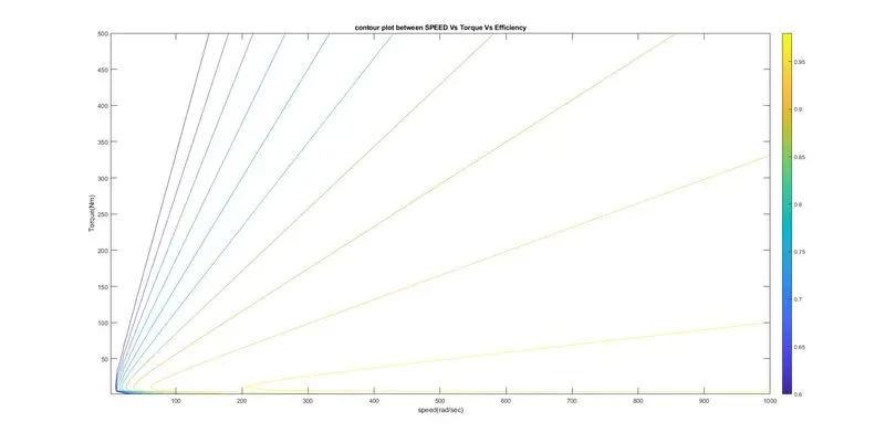
From the above Contour plot we can find the efficiency of the motor at which the motor's speed and torque is present.
And also from the above results based on the efficiency we can decide the motor that can be used to get the good output performance.
We can also find the better efficiency operating region of motor at a particular speed and torque.
CONCLUSION :
- Calculated energy required for braking for particular cases in driving cycle.
- Discussed about the braking strategies and why braking torque is not exact as starting torque.
- Plotted the Contour plots between the Speed,Torque and Efficiency.
GOOGLE DRIVE LINK :
QUESTION 1:
QUESTION 3: