Week 11 Car Crash simulation
1. Objective
To perform an explicit dynamic analysis to perform a frontal crash simulation of a car.
To provide three different thickness values and make conclusions on that basis.
2. Model and Material
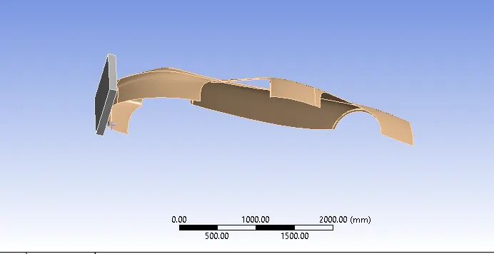
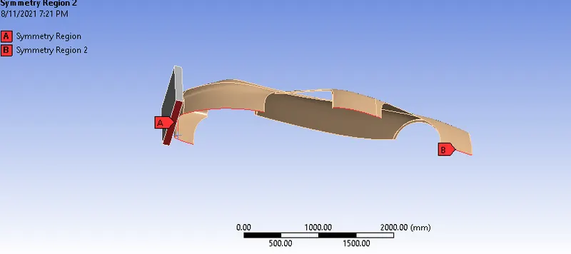
The model was imported in .stp format. Stainless Steel NL was specified as the material from the ANSYS material library. Then the geometries were named as car body and wall. Along with that, symmetric conditions were applied for both the wall and the car to imitate the full-body model.
Geometry
Symmetry
3. Meshing and Setup
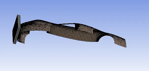
The model was meshed using elements of 75 mm size for both the wall and the car. The total number of nodes and elements were 8428 and 7907 respectively. Inside Analysis settings, the end time was set to 0.0001 s whereas the rest of the parameters were kept the same.
4. Assignment of boundary conditions
a. Fixed Support
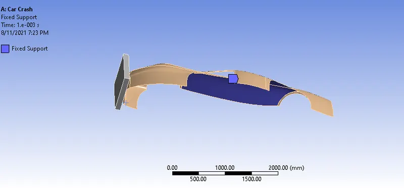
The car parts that wouldn't involve or have a significant role in the collision are provided fixed support as shown in the figure above.
b. Displacement
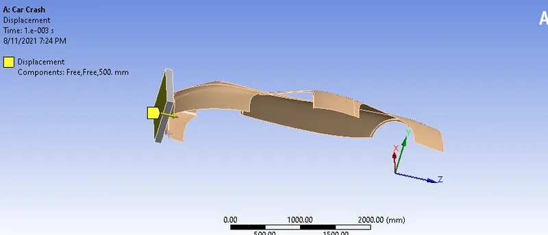
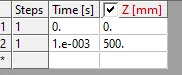
The back face of the wall was given a displacement of 500 mm in Z-direction to imitate the block moving forward. The displacement given is such that it is 0 initially and reaches 500 mm in 1e-3 s.
5. Results
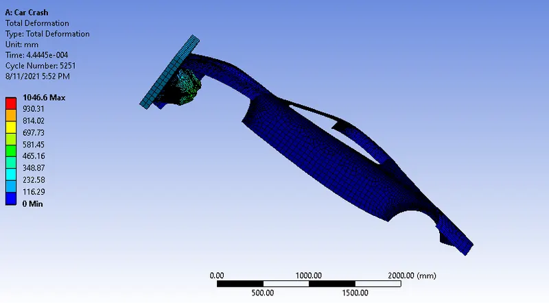
a. When thickness=0.3 mm
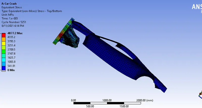
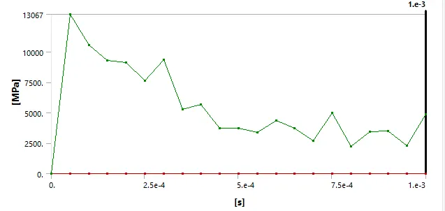
Equivalent Stress
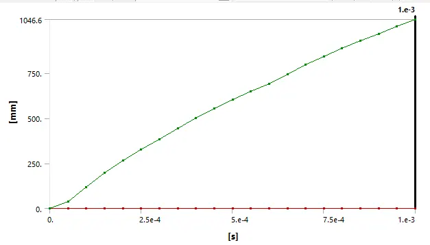
Total Deformation
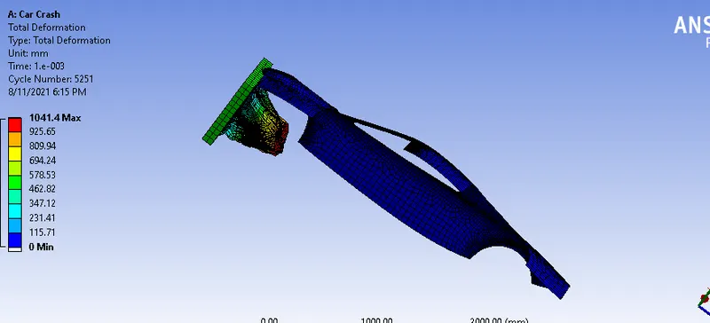
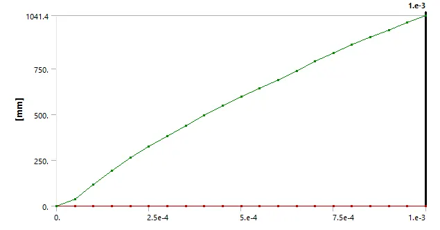
b. When t=0.6 mm
Equivalent Stress
Total Deformation
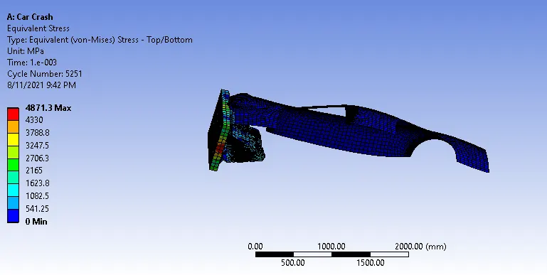
c. When thickness=0.9 mm
Equivalent Stress
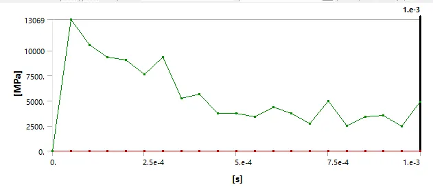
Total Deformation
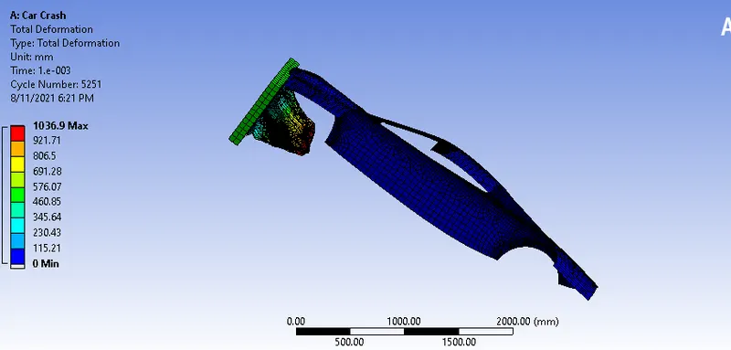
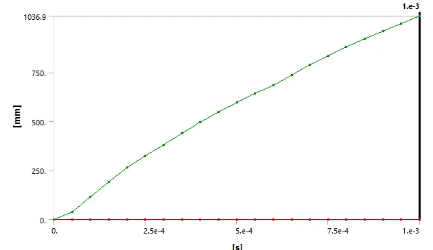
Summary of the Results
t Equivalent Stress Total Deformation
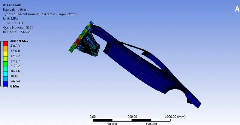
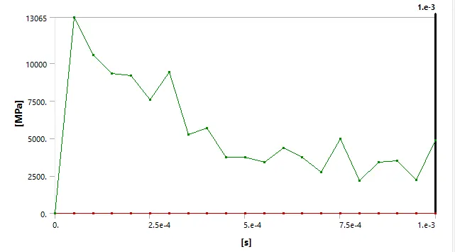
0.3 mm 4882.9 MPa 1046.6 mm
0.6 mm 4877.2 MPa 1041.1 mm
0.9 mm 4871.3 Mpa 1036.9 mm
6. Analysis
From the results, it is observed that the values of equivalent stress and total deformation decreased with the increasing thickness value. The stress and total deformation are maximum for the car body with 0.3 mm thickness whereas they are minimum for the car body with a thickness of 0.9 mm.