Week 10 Thermal Management
- It is a very popular question that "Why does an electric car battery pack need a thermal management system"? Lets see a recent news of Hyundai Kona
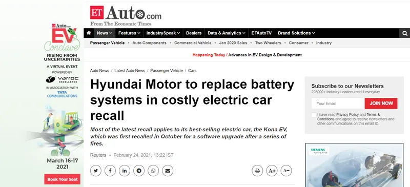
- Most of the latest recall applies to its best-selling electric car, the Kona EV, which was first recalled in October for a software upgrade after a series of fires. So there is an instance of a battery pack catching fire lets see why:
- The charge from a battery is bled during runtime and charging is done when soc of cells are below certain limits. The current flow during charging and discharging generates heat and this is proportional to the square of the flowing current multiplied by the internal resistance of the cells and the interconnect systems. The higher the current flow the more heating will be produced.
- From a thermal point of view, there are three main aspects to consider when using lithium-ion batteries in an EV:
- When the temperature of the battery pack is less than 0°C batteries lose charge due to slower chemical reactions taking place in the battery cells. The results in loss of power, acceleration and driving range, and higher potential for battery damage during charging.
- When the temperatures are above 30°C the battery performance degrades, posing a real issue if a vehicle’s air conditioner is needed for passengers. The result is an impact on power density and reduced acceleration response.
- It is mayhem if the temperatures are above 40°C leading to serious and irreversible damage in the battery. At even higher temperatures, e.g. 70-100°C, thermal runaway can occur. This is triggered when the runaway temperature is reached. The result is a self-heating chain reaction in a battery cell that causes its destruction while propagating to adjacent cells.
- An EV battery pack needs an effective thermal management system because of three primary reasons:
- To ensure the pack operates in the desired temperature range for optimum performance and working life. A typical temperature range is 15-35°C.
- To reduce uneven temperature distribution in the cells. Temperature differences should be less than 3-4C°.
- To eliminate potential hazards related to uncontrolled temperature, e.g. thermal runaway.
- Therefore, the management of batteries is necessary in order to reach maximum performance when operating at various conditions. One important point to note here is that these technologies to effectively manage the thermal part of the Battery pack are essentially a trade-off between performance, cost, reliability, cost and energy consumption among other things. The different thermal management techniques used in EVs are:
- 1. Air Cooling System(Cooling and Heating)
- Air is employed as a thermal medium. The air taken in for cooling is either ambient air or from the cabin. The air could also be from conditioned air after a heater or evaporator of an air conditioner. When cabin or ambient air is employed to perform cooling it is called a passive cooling system while the second one obtained from a conditioner is referred to as an active system. Active systems can offer additional cooling or heating power. A passive system can offer some hundreds of watts of cooling or heating power and the active system power is limited to 1 kW.
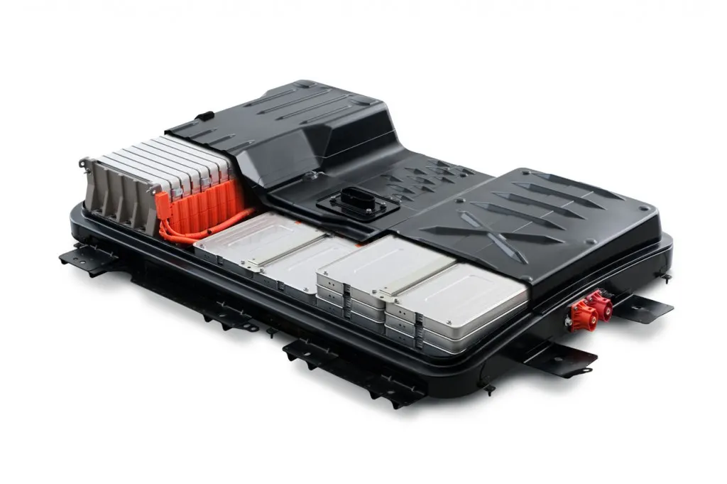
- In both cases air is provided by a blower hence also known as forced air systems. The schematic of a passive system is represented below along with air cooled pack in nissan leaf
-
- 2. Liquid Cooling System(Cooling and Heating)
-
The battery pack just like it need cooling it needs heating as well. Liquids can also be used as a medium for transferring heat effectively. For thermal management applications generally, two liquids are preferred One is a di-electric liquid, also called a direct-contact liquid, which can contact the battery cells directly, such as mineral oil. The other being conducting liquid (indirect-contact liquid) which can only contact the battery cells indirectly, such as a mixture of ethylene glycol and water.
-
Depending upon the liquids used the layout of a thermal management system also varies.
-
For direct-contact liquid, the normal layout is to submerge modules in mineral oil. For indirect-contact liquid, a possible layout can be either be a jacket around the battery module, discrete tubing around each module, placing the battery modules on a cooling/heating plate or combining the battery module with cooling/heating fins and plates.
-
Out of the two indirect contact systems are preferred in order to achieve better isolation between the battery module and surroundings and thereby offer better safety.
-
Depending on the heat sinks used for cooling liquid cooling systems can be classified into either passive systems or active systems.
- In the passive liquid system, the heat-sink for cooling is a radiator. It lacks heating ability. The representation of a passive cooling system is shown below
- The fluid that is used to make the heat transfer possible is circulated with a pump and forms a closed loop. The circulating fluid absorbs heat from the battery pack and releases heat by making use of a
radiator. The cooling power depends strongly on the temperature between ambient air and battery. Fans behind the radiator can improve the cooling performance, but if the ambient air is higher than the battery temperature or the difference between them is too small, the passive liquid system becomes ineffective. An active system is represented below alon with a liquid cooled pack in chevy bolt:
-
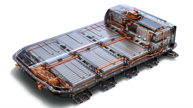
- There are two loops the top one is called the primary loop whereas the lower one is called the secondary loop. The primary loop is similar to the loop in a passive liquid system, where the heat transfer fluid is circulated by the pump. The secondary loop is actually an air conditioning loop (A/C loop). The upper heat exchanger works as an evaporator (EVAP) for cooling operation and connects both loops.
- During heating operation, the 4-way valve will be switched, and the upper heat exchanger works as a condenser (COND) and the lower heat exchanger works as an evaporator. The heating operation loop is also called the heat pump loop.
- 3. Direct Refrigerant(Cooling and Heating)
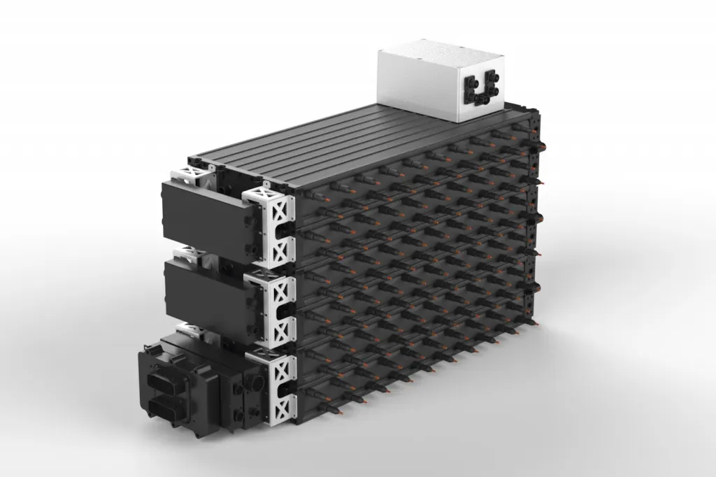
- Cooling can be also done by employing a refrigerant. The direct refrigerant system(DRS) consists of an A/C loop that uses a DRS refrigerant directly as a heat transfer fluid circulating through battery pack. Such a method is still at a nascent stage that is in R&D phase with none being deployed in cars that are on road . As the battery is in direct contact with the coolant there prerqquisite that the coolant shouldi have no conductivity. A liquid immersion technology is developed by XING Mobility by immersing its cells in a non-conductive fluid with a high boiling point. The coolant is 3M Novec 7200 Engineered Fluid, a non-conductive fluid designed for heat transfer applications, fire suppression and supercomputer cooling.
- 4. Indirect Refrigerant System
-
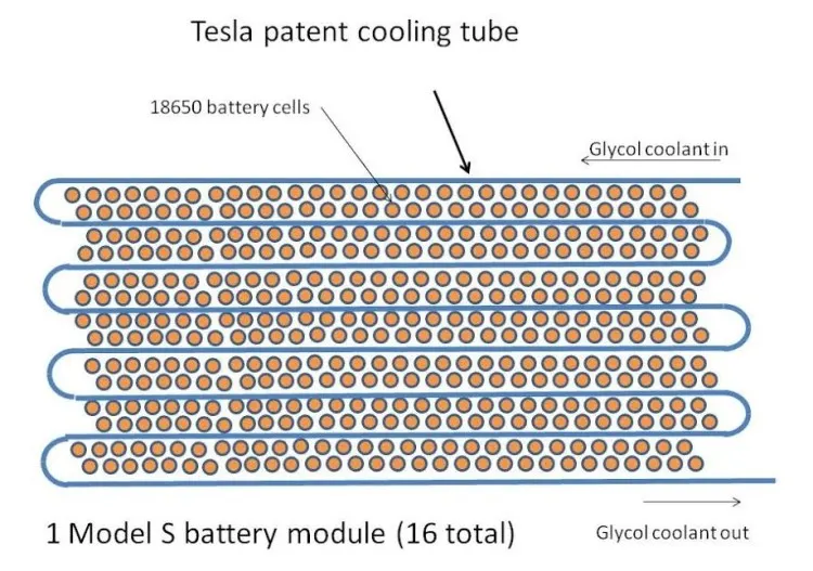
The indirect cooling systems used are similar to the ones used in ICE vehicles wherein a liquid coolant circulates through a system of metal pipes placed in a series manner. The construction is in such a way that the maximum uniformity in temperature distribution is achieved. The coolants employed are glycol or polyglycol, but the 1% additive package is what separates good from great engine protection and performance. When circulating a liquid coolant throughout metal piping, it is important to protect against corrosion to protect vehicle safety and performance.
- Usage of glycoel for cooling in tesla model S. The Tesla Model S battery cooling system consists of a patented serpentine cooling pipe that winds through the battery pack and carries a flow of water-glycol coolant; thermal contact with the cells is through their sides by thermal transfer material.
- 5. Phase change materials (PCM)
-
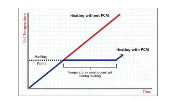
During melting, heat is absorbed by PCM and is stored as latent heat until the latent heat is up to the maximum. The temperature is kept at the melting point for a period and the temperature increase is delayed. Therefore, PCM is used as a conductor and buffer in battery thermal management systems.
- the working mechanism of is demonstrated in the image below on battery cells. Also, a PCM is always combined with an air cooling system or liquid cooling system to manage the battery temperature.
- 6. Thermoelectric Module
-
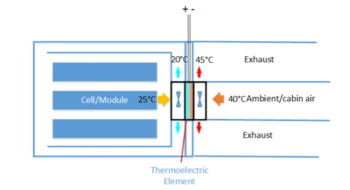
The thermoelectric module can convert the electric voltage to temperature difference and vice versa. Here the former effect is adopted. That means it transfers heat through the module by consuming electricity directly
-
A thermoelectric (TE) module also known as Pel
tier cooler is a semiconductor-based electronic component that functions as a small heat pump, moving heat from one side of the device to the other side -
Thermoelectric modules are also sometimes used to generate electricity by using a temperature differential between the two sides of the module.
-
Two fans are installed to improve heat transfer by forced convection. To combine a passive air system with a thermoelectric module, the combined system is able to cool down the battery even lower than the intake air temperature. It is easy to switch between cooling and heating operations. To achieve that, the poles of
electrodes need to be reversed. - 7. Heat Pipe
-
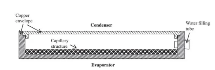
Just like usage of a thermo-electric module to upgrage a passive air system anothetr choice is a heat pipe. The flat copper envelope of the heat pipe is under a state of partial vacuum. The capillary structure is made of sintered copper powder. The heat pipe uses water as the working fluid. Water on the evaporator side will absorb heat and become vapor at a temperature lower 100°C due to low pressure inside. Water on the condenser will dissipate heat to the surrounding and become liquid again. This cycle repeats ..
-
Note that, in comparison to thermo-electric, a heat pipe is more reliable, because there are no moving parts and no energy consumption. However, a heat pipe is unable to heat the battery due to its fixed structural layout.
-
Heating the battery at a low temperature is not possible or is difficult.
- The above listed systems are mandate and are proven to be good but it is always advisable to have a combination of two prime battery thermal management systems are recommended: combined liquid system (CLS) and a variant system with PCM.
- References:
1. https://avidtp.com/what-is-the-best-cooling-system-for-electric-vehicle-battery-packs/
2. Hu, X., Battery Thermal Management in Electric Vehicles. Ansys, Inc., 2011.
3. https://www.mpoweruk.com/chemistries.htm
4. Wang, Q., Jiang, B., Xue, Q., Sun, H., Li, B., Zou, H. and Yan, Y., Experimental Investigation on EV Battery Cooling and Heating by Heat Pipes, Applied Thermal Engineering, 2015.
5. Rugh, J., Pesaran, A. and Smith, K., Electric Vehicle Battery Thermal Issues and Thermal Management Techniques, NREL, SAE Alternative Refrigerant and System Efficiency Symposium, 2011.v