Week 10 - Simulation of Flow through a pipe in OpenFoam
Simulation of Flow through a pipe in OpenFoam
Aim:-
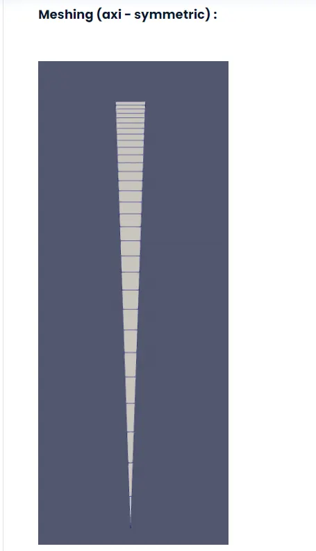
- In this project we are going to simulate an axi-symmetric flow by applying the wedge boundary condition.
- Since the flow is laminar and its flows through a constant Cross-section pipe at a given inlet Reynold's No of 2100.
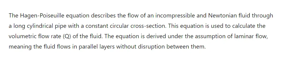
- Also validate result with the Hagen-poiseuille's equation for the fully developed flow.
Description:-
The project involves simulating the Hagen-Poiseuille flow, which describes the movement of an incompressible fluid through a circular pipe. To simplify the simulation, only a small section (or wedge) of the pipe is modeled, using a wedge angle of 5 degrees. Here's a step-by-step explanation of the process:
Axi-Symmetric Flow: The flow is symmetric around the pipe's axis, so instead of simulating the entire pipe, we simulate a small wedge-shaped section. This reduces the complexity of the simulation.
Mesh Generation with MATLAB: A MATLAB script is written to automatically create a computational mesh for this wedge section. The mesh is defined in a file called
blockMeshDict.Creating
blockMeshDictFile: The MATLAB program generates theblockMeshDictfile, which specifies the geometry and mesh details of the wedge section.Setting Up the Simulation Folder: The generated
blockMeshDictfile is placed in a specific directory called the "run folder." This folder is copied from the "foam folder," which contains the necessary templates and settings for the simulation.Choosing the Solver: The solver used for this simulation is
icoFoam, which is located in the "incompressible" folder.icoFoamis a solver for incompressible laminar flow using the Navier-Stokes equations, which govern the movement of fluid.Running the Simulation: The wedge section is simulated in the run folder using
icoFoam.Post-Processing with ParaFoam: After the simulation is complete, the results are visualized using
paraFoam. This tool helps to observe the velocity profile of the flow at different points along the pipe.Observing Flow Profiles: Specifically, the velocity profile is observed at two critical points:
- Hydrodynamic Entrance Length: This is the region near the pipe entrance where the flow is still developing.
- Fully Developed Flow: This is the region further along the pipe where the flow has stabilized and has a consistent velocity profile.
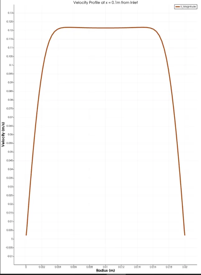
Validating Results: The results from the CFD (Computational Fluid Dynamics) simulation are compared with the theoretical predictions from the Hagen-Poiseuille equations. This ensures that the simulation is accurate and reliable.
By following these steps, you can effectively simulate and analyze the flow of an incompressible fluid through a pipe using a small, manageable section of the pipe.
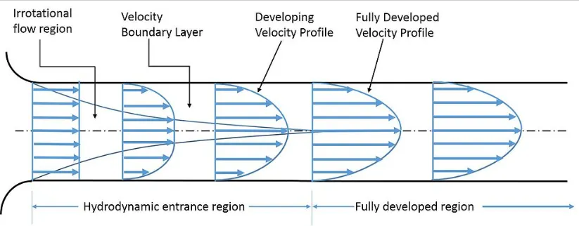
Hydrodynamic Entrance and Fully Developed Flow Regions
When fluid enters a pipe, its flow behavior can be divided into two main regions:
Hydrodynamic Entrance Region:
- Irrational Flow Region: This is right at the entrance where the fluid flow hasn't yet been influenced by the pipe walls.
- Velocity Boundary Layer: As the fluid moves further into the pipe, a thin layer of fluid close to the walls starts to slow down due to friction. This is called the boundary layer.
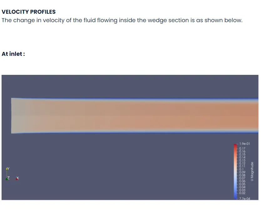
- Developing Velocity Profile: The boundary layer grows thicker as the fluid moves down the pipe. The flow speed near the walls decreases, while the flow speed in the center remains high. This causes the velocity profile (the shape of the speed distribution across the pipe) to develop and change.
Fully Developed Region:
- Fully Developed Velocity Profile: After some distance, the velocity profile stops changing and becomes stable. This means the fluid speed at each point across the pipe's cross-section remains constant as it flows further. This is the fully developed flow.
Entrance Length
The entrance length is the distance from the pipe entrance to the point where the flow becomes fully developed. During this length, the velocity profile is still evolving.
Shear Stress in the Pipe
- Shear Stress at the Entrance: At the very start of the pipe, the wall shear stress (friction between the fluid and the pipe wall) is the highest because the boundary layer is very thin.
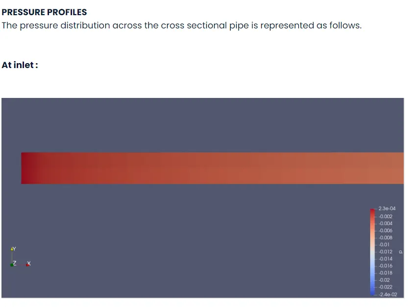
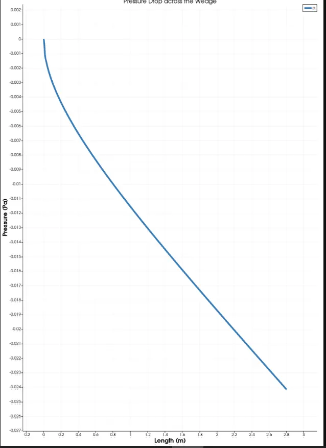
- Shear Stress Along the Pipe: As the fluid travels further, the boundary layer thickens, and the shear stress decreases. The pressure drop is also highest in the entrance region due to this high shear stress.
In summary:
- When fluid enters the pipe, its flow starts to develop due to the pipe walls' friction.
- Initially, the velocity profile changes until it becomes fully developed.
- The entrance length is the distance required for this fully developed flow to be achieved.
- Shear stress is highest at the entrance and decreases along the length of the pipe.
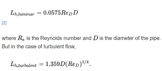
>The hydrodynamic entrance length can be calculated by using the formula(laminar formula),
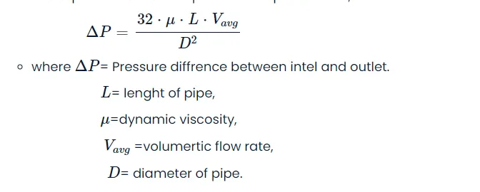
Deriving the solution for given parameters
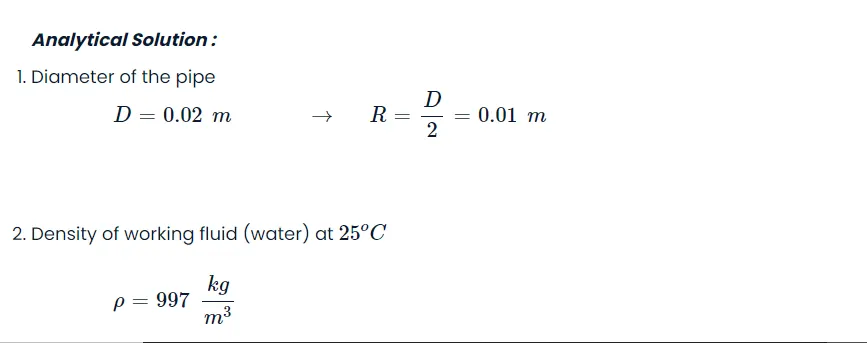
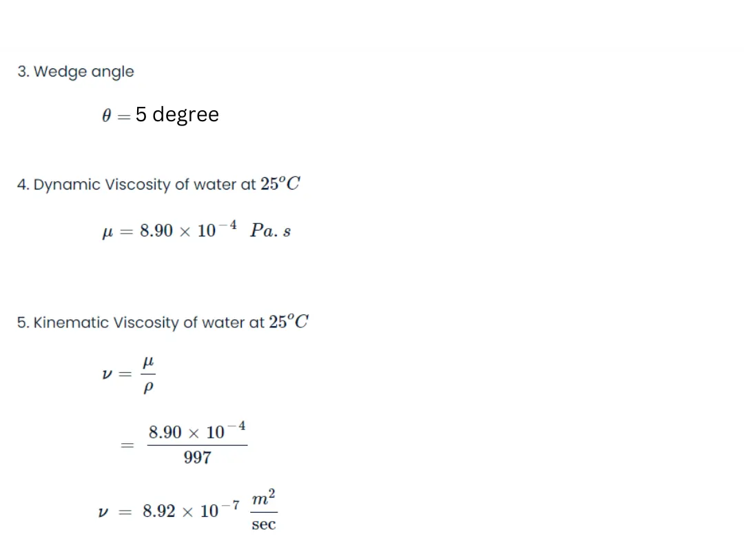
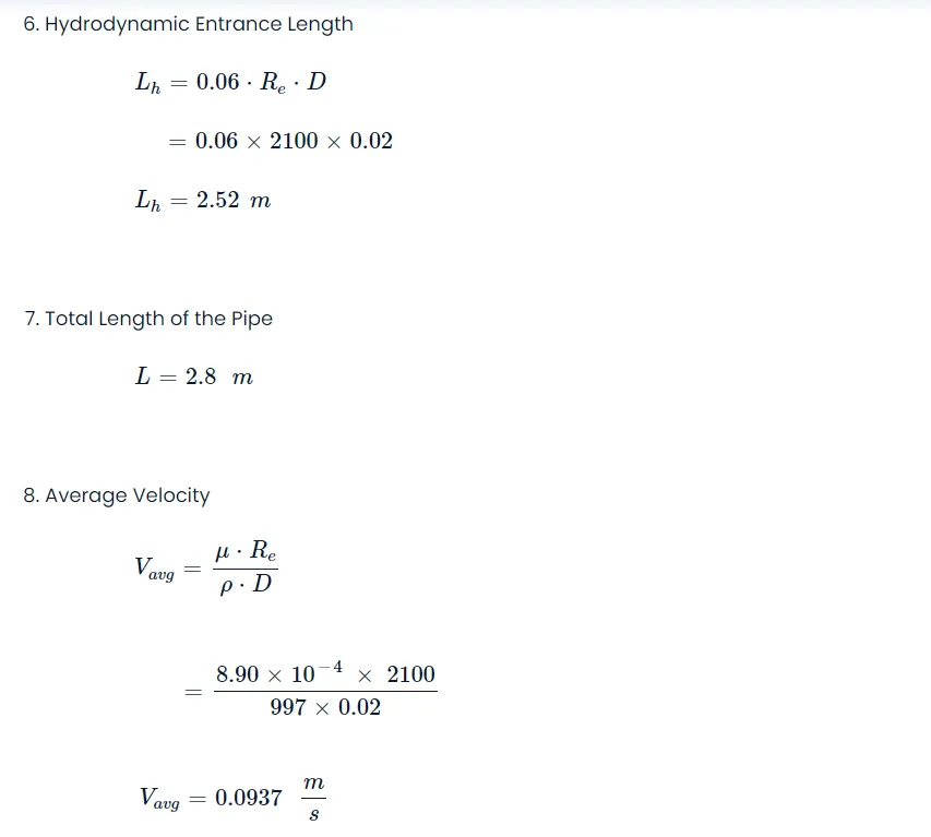
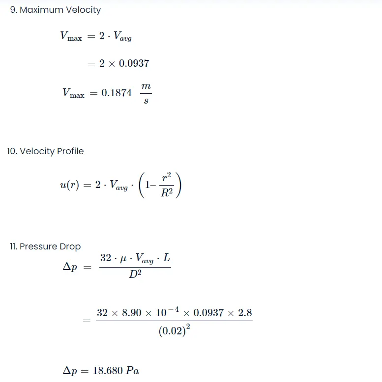
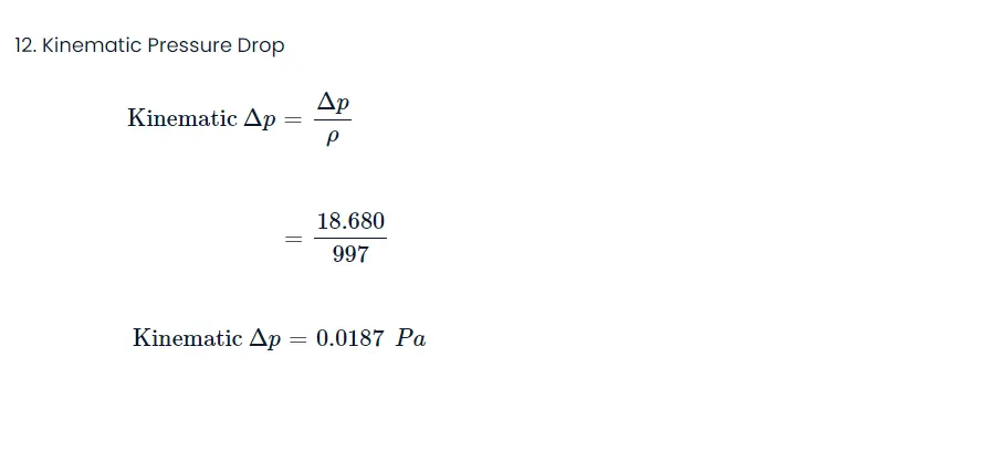
⋅μ⋅L⋅Vavg
% SIMULATION OF FLOW THROUGH A PIPE
% Code to automate generation of blockMeshDict file
clear all
close all
clc
We generate the blockMeshDict file by calculating the vertices of the wedge using the formulas R⋅cos(θ/2) and R⋅sin(θ/2) relative to the wedge's axis.
The fprintf command in our code is used to write the content into the blockMeshDict file, producing the following text file.
Using the calculated vertices, we create the wedge geometry with a hexahedral mesh. To achieve finer meshing along the walls, we apply a grading factor of 0.1 for this simulation.
The number of cells along the x, y, and z axes are set to 400, 30, and 1, respectively.
An arc representing the radius of the wedge is created, and we define the input, output, axis, wall, front, and back faces of the wedge.
blockMeshDict File :
/*--------------------------------*- C++ -*----------------------------------*\
  =========                 |
  \\      /  F ield         | OpenFOAM: The Open Source CFD Toolbox
   \\    /   O peration     | Website:  https://openfoam.org
    \\  /    A nd           | Version:  9
     \\/     M anipulation  |
\*---------------------------------------------------------------------------*/
FoamFile
{
    format      ascii;
    class       dictionary;
    object      blockMeshDict;
}
// * * * * * * * * * * * * * * * * * * * * * * * * * * * * * * * * * * * * * //

convertToMeters 1;

vertices
(
	(0 0 0)
	(0 0.009994 -0.000349)
	(0 0.009994 0.000349)
	(2.80 0 0)
	(2.80 0.009994 -0.000349)
	(2.80 0.009994 0.000349)
);

blocks
(
	hex (0 3 4 1 0 3 5 2) (400 30 1) simpleGrading (1 0.1 1)
);

edges
(
	arc 2 1 (0 0.010 0)
	arc 5 4 (2.800 0.010 0)
);

boundary
(
	axis
	{
		type empty;
		faces
		(
			(0 3 3 0)
		);
	}

	inlet
	{
		type patch;
		faces
		(
			(0 1 2 0)
		);
	}

	outlet
	{
		type patch;
		faces
		(
			(3 5 4 3)
		);
	}

	front
	{
		type wedge;
		faces
		(
			(0 3 4 1)
		);
	}

	back
	{
		type wedge;
		faces
		(
			(0 2 5 3)
		);
	}

	pipeWall
	{
		type wall;
		faces
		(
			(1 4 5 2)
		);
	}
);

mergePatchPairs
(
);

// ************************************************************************* //
The blockMeshDict file has been written automatically by the MatLab program as shown above, which we use to create the geometry of the wedge and run the simulation for the same.
controlDict File :
/*--------------------------------*- C++ -*----------------------------------*\
========= |
\\ / F ield | OpenFOAM: The Open Source CFD Toolbox
\\ / O peration | Website: https://openfoam.org
\\ / A nd | Version: 9
\\/ M anipulation |
\*---------------------------------------------------------------------------*/
FoamFile
{
format ascii;
class dictionary;
location "system";
object controlDict;
}
// * * * * * * * * * * * * * * * * * * * * * * * * * * * * * * * * * * * * * //
application icoFoam;
startFrom startTime;
startTime 0;
stopAt endTime;
endTime 40;
deltaT 0.01;
writeControl timeStep;
writeInterval 200;
purgeWrite 0;
writeFormat ascii;
writePrecision 6;
writeCompression off;
timeFormat general;
timePrecision 6;
runTimeModifiable true;
// ************************************************************************ //
We run the simulation for a period of 40 seconds in timesteps of 0.01 seconds.
transportProperties File :
/*--------------------------------*- C++ -*----------------------------------*\
  =========                 |
  \\      /  F ield         | OpenFOAM: The Open Source CFD Toolbox
   \\    /   O peration     | Website:  https://openfoam.org
    \\  /    A nd           | Version:  9
     \\/     M anipulation  |
\*---------------------------------------------------------------------------*/
FoamFile
{
    format      ascii;
    class       dictionary;
    location    "constant";
    object      transportProperties;
}
// * * * * * * * * * * * * * * * * * * * * * * * * * * * * * * * * * * * * * //

nu              [0 2 -1 0 0 0 0] 8.9268e-07;


// ************************************************************************* //
We input the calculated value of Kinematic viscosity of water 25 degree Celsius as 8.92 x 10^-7 m^2/sec
Initial Velocity (U) File :
/*--------------------------------*- C++ -*----------------------------------*\
========= |
\\ / F ield | OpenFOAM: The Open Source CFD Toolbox
\\ / O peration | Website: https://openfoam.org
\\ / A nd | Version: 9
\\/ M anipulation |
\*---------------------------------------------------------------------------*/
FoamFile
{
format ascii;
class volVectorField;
object U;
}
// * * * * * * * * * * * * * * * * * * * * * * * * * * * * * * * * * * * * //
dimensions [0 1 -1 0 0 0 0];
internalField uniform (0.0937 0 0);
boundaryField
{
axis
{
type empty;
}
inlet
{
type fixedValue;
value uniform (0.0937 0 0);
}
outlet
{
type zeroGradient;
}
front
{
type wedge;
}
back
{
type wedge;
}
pipeWall
{
type noSlip;
}
}
// ************************************************************************* //
We define the velocity condition at the inlet of pipe V (avg) as 0.0937 m/s
Initial Pressure (p) File :
/*--------------------------------*- C++ -*----------------------------------*\
========= |
\\ / F ield | OpenFOAM: The Open Source CFD Toolbox
\\ / O peration | Website: https://openfoam.org
\\ / A nd | Version: 9
\\/ M anipulation |
\*---------------------------------------------------------------------------*/
FoamFile
{
format ascii;
class volScalarField;
object p;
}
// * * * * * * * * * * * * * * * * * * * * * * * * * * * * * * * * * * * * * //
dimensions [0 2 -2 0 0 0 0];
internalField uniform 0;
boundaryField
{
axis
{
type empty;
}
inlet
{
type zeroGradient;
}
outlet
{
type zeroGradient;
value uniform 0.0187;
}
front
{
type wedge;
}
back
{
type wedge;
}
pipeWall
{
type zeroGradient;
}
}
// ************************************************************************* //
The kinematic pressure drop is 0.0187 PA