Week 10 - Simulating Combustion of Natural Gas.
week 10 challenge:
Aim:
to perform a combustion simulation on the combustor model and plot the variation in mass fraction of species.
Introduction:
A combustor is a component or area of a gas turbine, ramjet, or scramjet engine where combustion takes place. It is also known as a burner, combustion chamber or flame holder.The metals usually considered for the combustor are nickel based alloys due to their high temperature capability. Alloy C263 is a nickel superalloy often used as it has high strength, good corrosion resistance, with good formability and high temperature ductility in welded structures.Large industrial gas turbines, where the space required by the combustion system is less critical, have used one or two large cylindrical combustion chambers.All turbine engines have a combustor, or burner, in which the fuel is combined with high pressure air and burned.
The resulting high temperature exhaust gas is used to turn the power turbine and produce thrust when passed through a nozzle. Burners are also used on ramjet and scramjet propulsion systems.The important function of the combustor is to efficiently mix air with the fuel and burn it in a manner that provides a high stagnation temperature with small losses in stagnation pressure and low pollutant emissions.
A simulation is a model that mimics the operation of an existing or proposed system, providing evidence for decision-making by being able to test different scenarios or process changes. This can be coupled with virtual reality technologies for a more immersive experience.the simulation process are the i) pre-processing ii)processing iii) post-processing
simulation:
pre-processing:
open the ansys workbench and save it as combustor.
then open the fluent flow system.
now open the geomentry, and import the given step file.
then close the geomentry window.
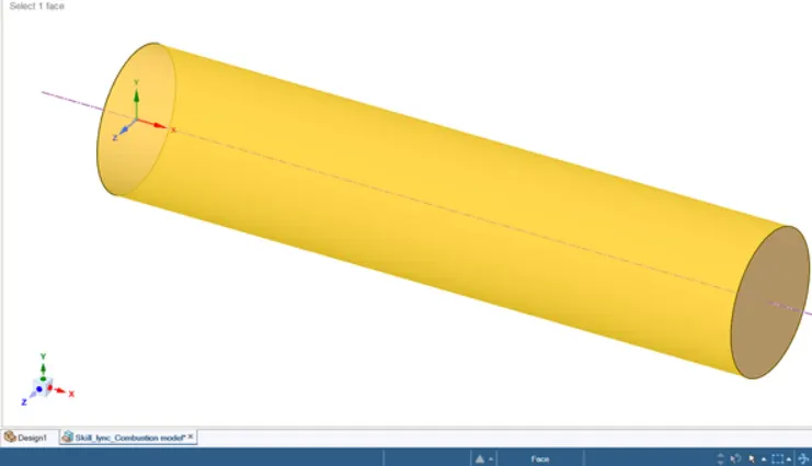
by using axis-symmetry method .
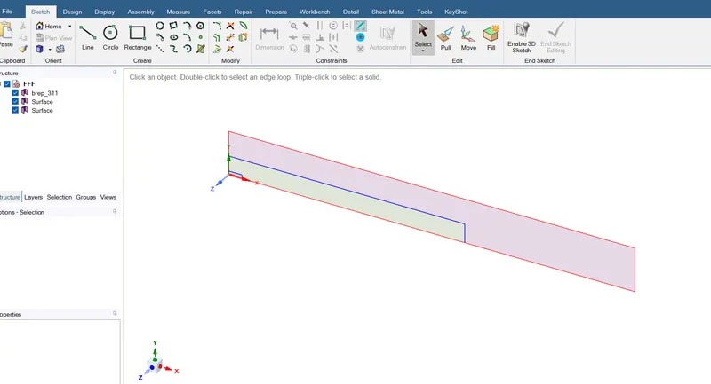
final geomentry.
mesh:
now double click on mesh to open the fluent mesh,
name the edges with inlet1, inlet 2 , outlet, axis, wall
then create a default mesh and resize it with changing the mesh element size.
mesh size with 10mm and the capture proximity is enabled with gap factor of 3.
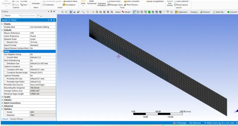
final mesh.
processing:
then double click on setup to open the ansys fluent processor.
Mesh information
Number of Nodes: 16770
Number of Elements: 16123
Tetrahedra: 0
Wedges: 16123
Pyramids: 0
Hexahedra: 0
Polyhedra: 0
Case setup:
Solver type = Pressure based
Solver time = steady state
Viscous model = k-epsilon
Energy equations = enabled
Species model
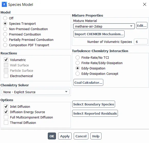
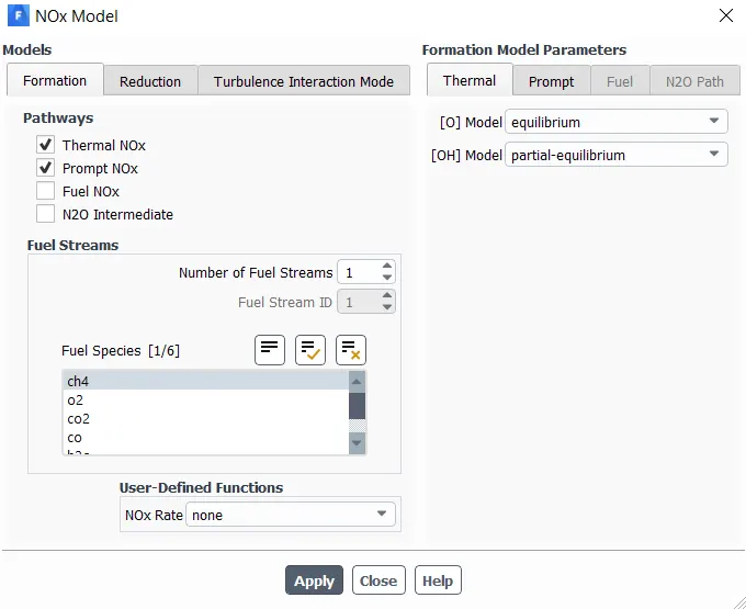
Nox model
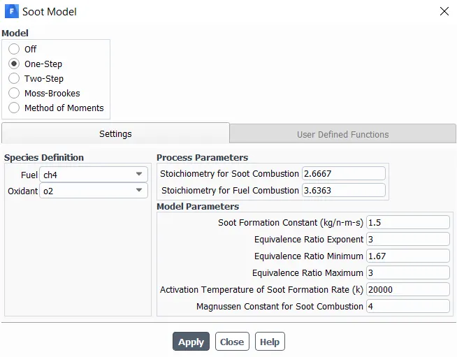
Soot model
Part 1
Boundary conditions
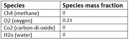
Air inlet
Velocity = 0.5 m/s
Temperature = 300 K
Species
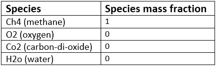
Fuel inlet
Velocity = 80 m/s
Temperature = 300 K
Species
Top surface
Boundary type = wall
Axis
x-axis = axisymmetric
Results of part 1
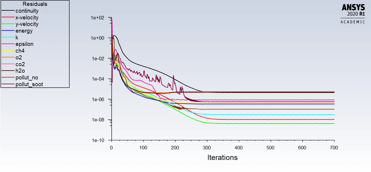
Residual plot
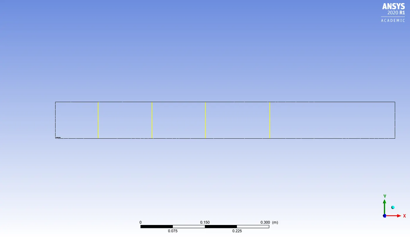
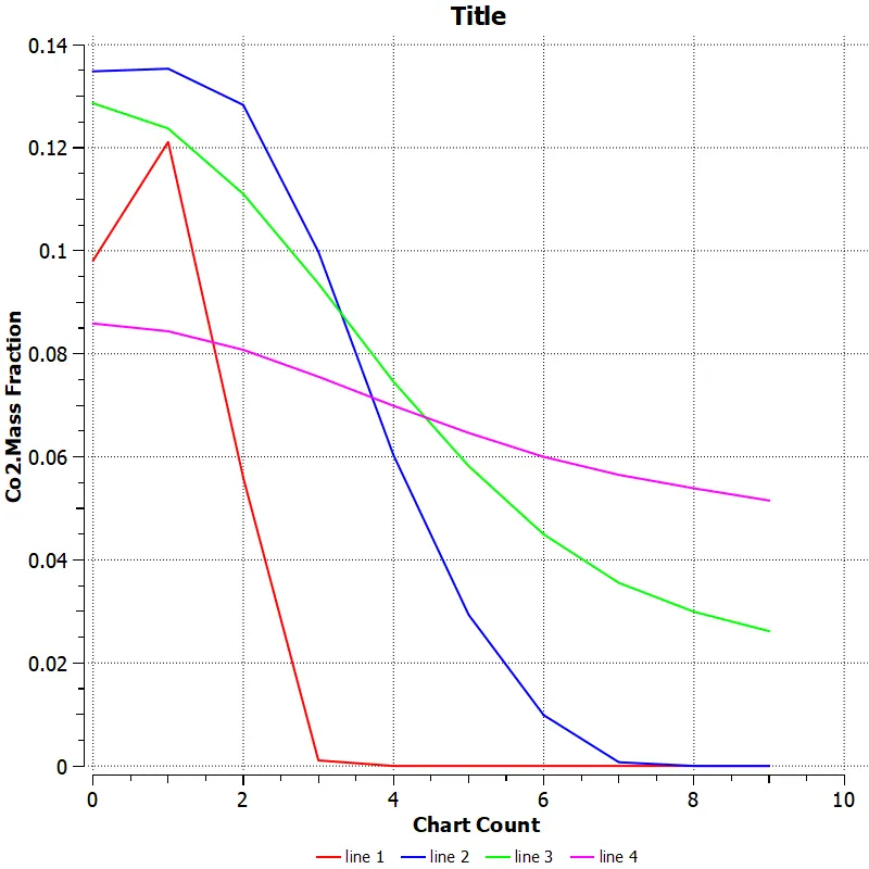
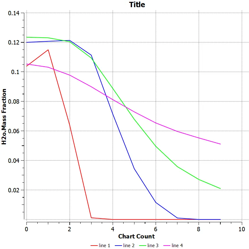
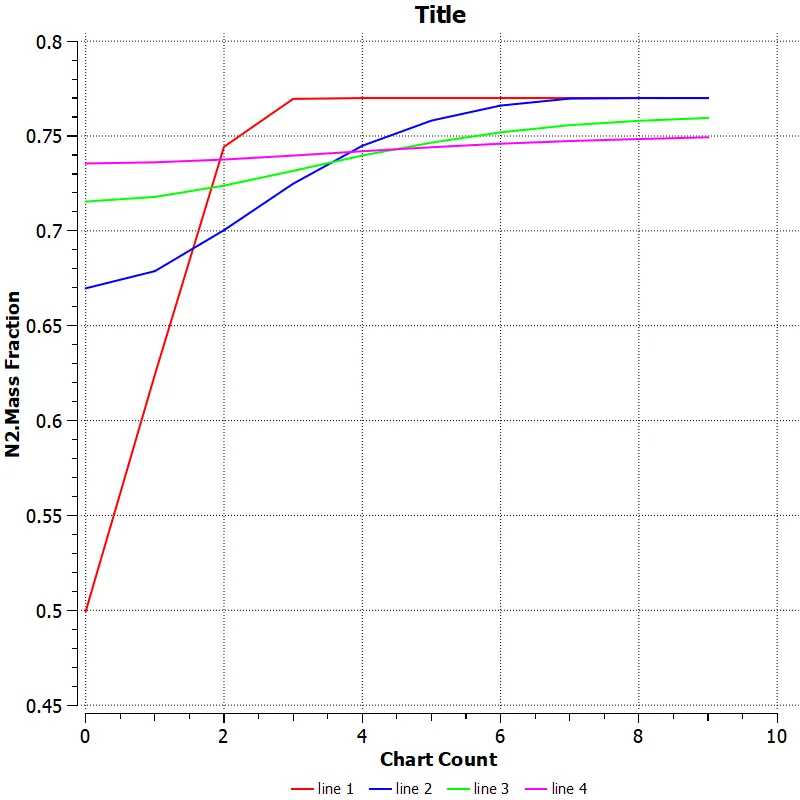
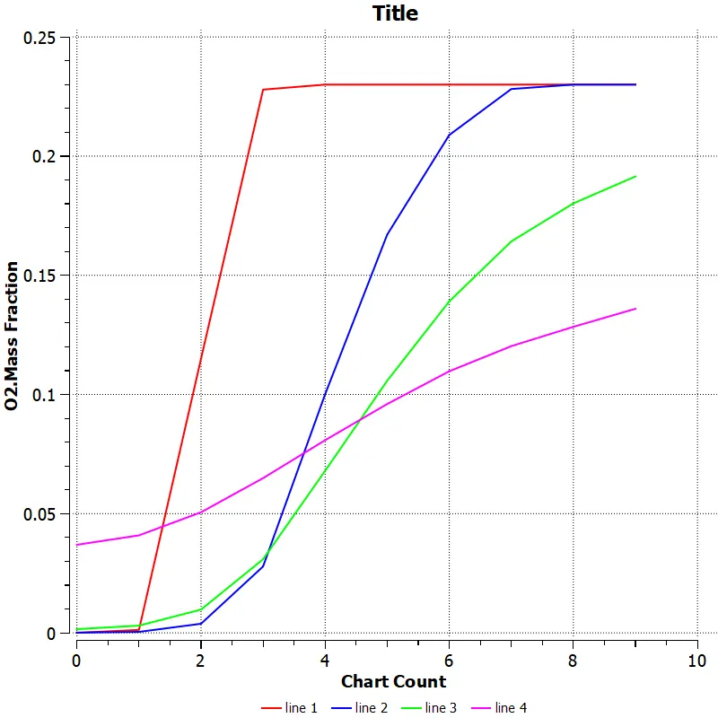
Line probes at different location of combustor
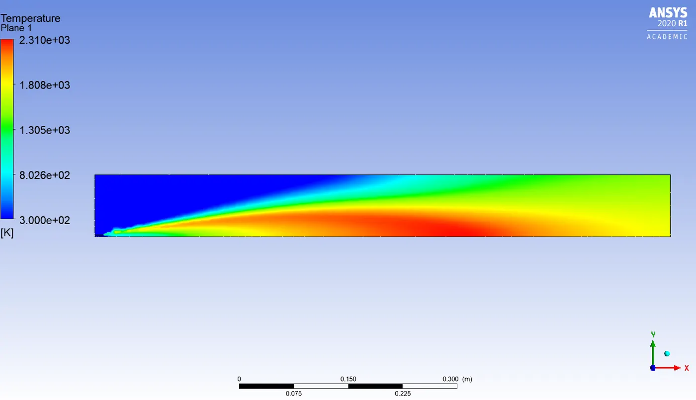
Temperature contour
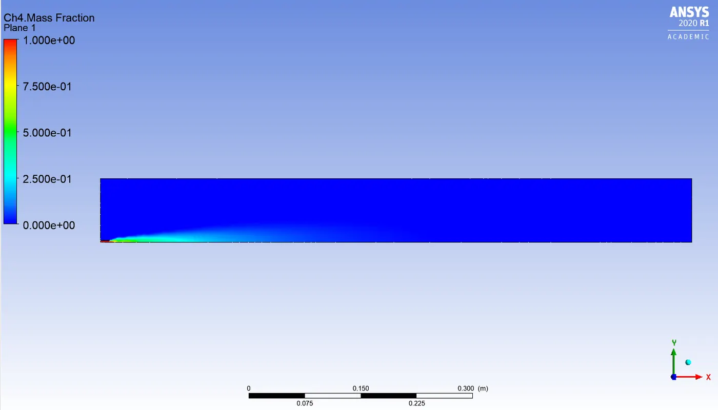
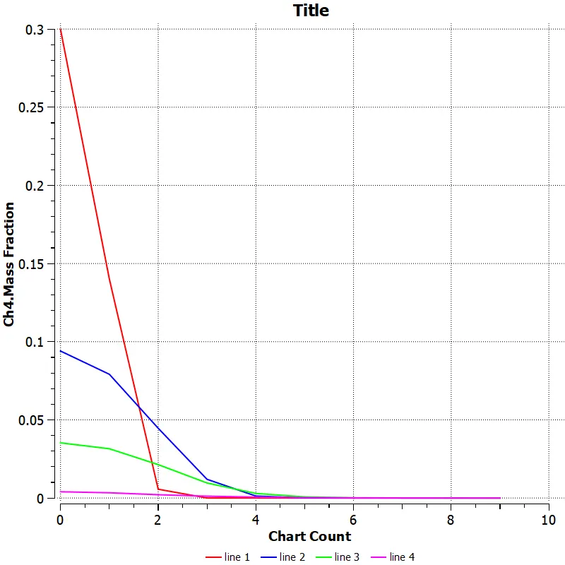
Ch4 mass fraction
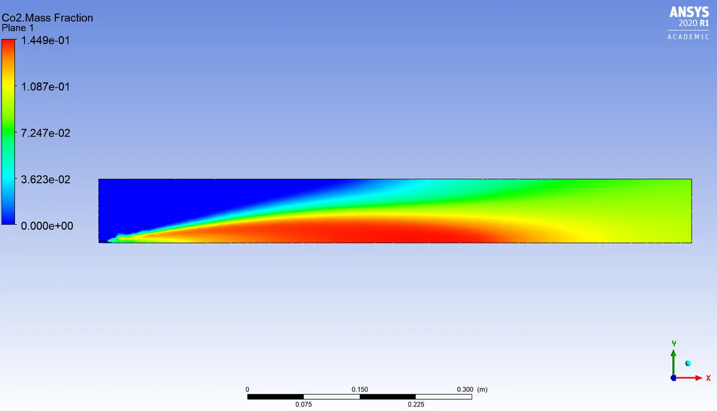
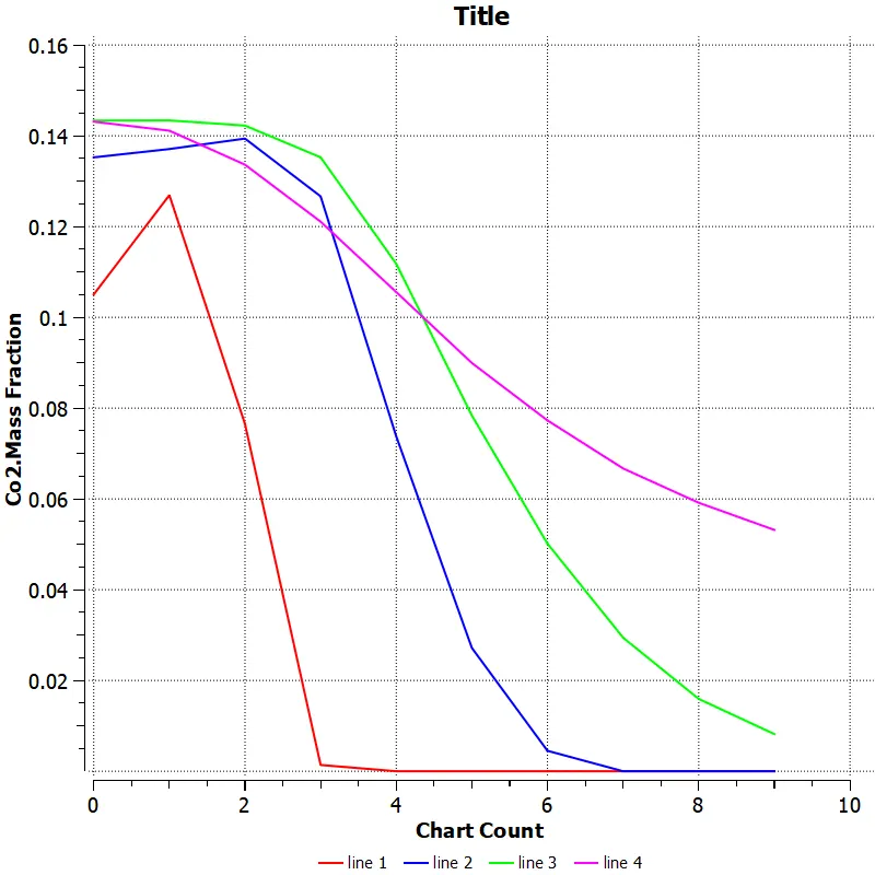
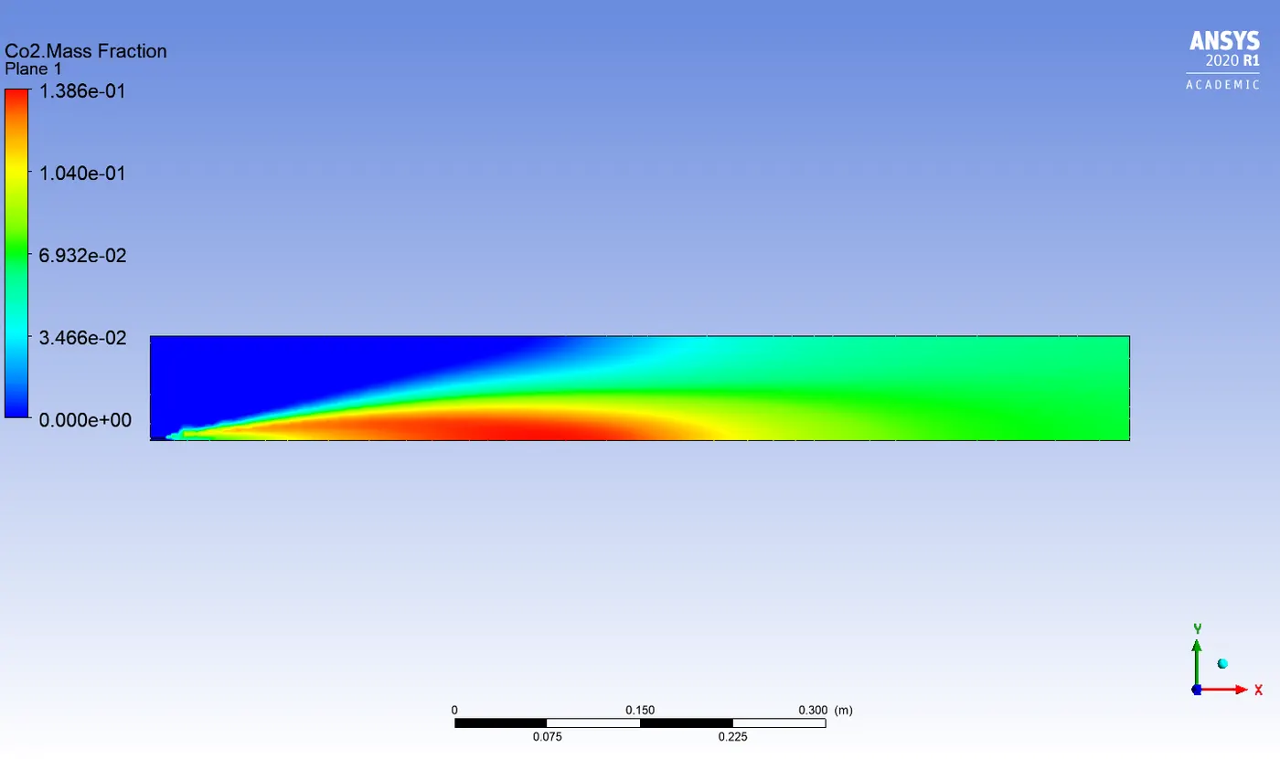
Co2 mass fraction
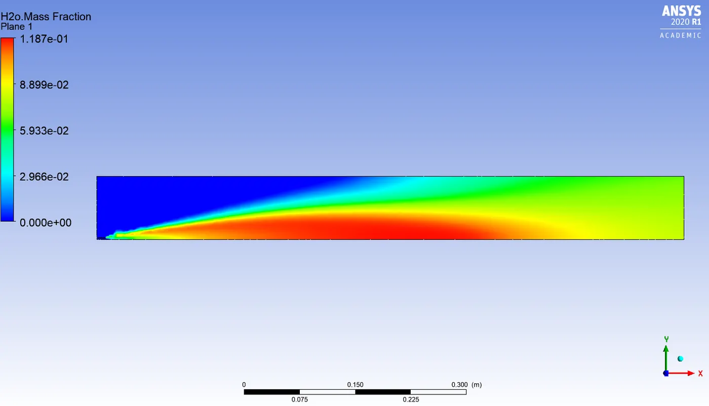
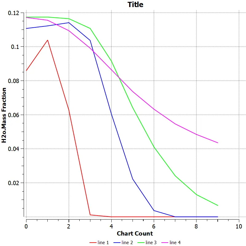
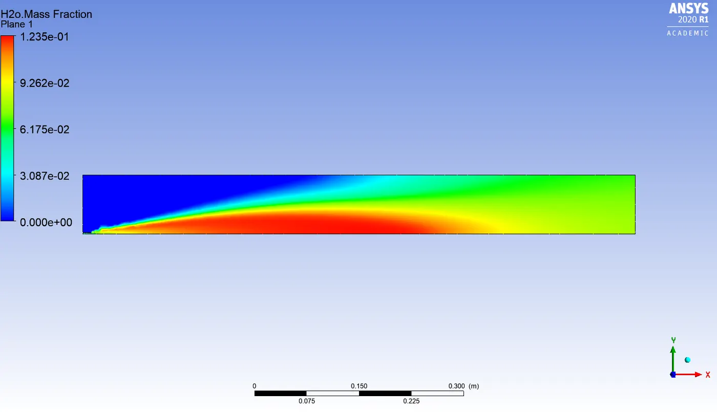
H2o mass fraction
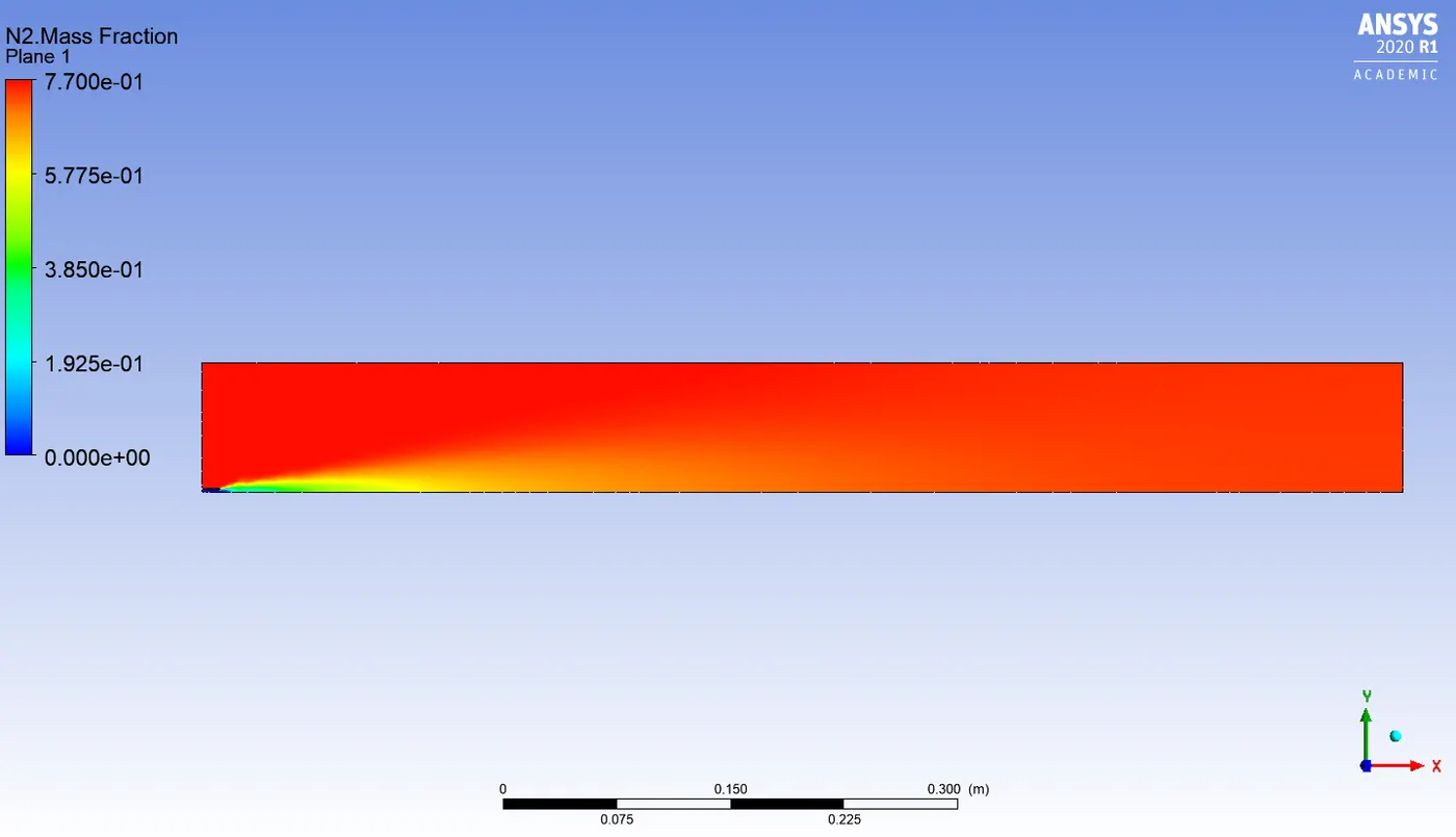
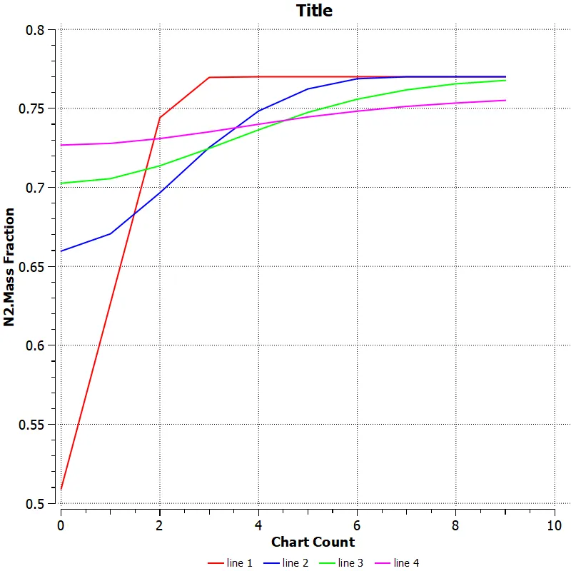
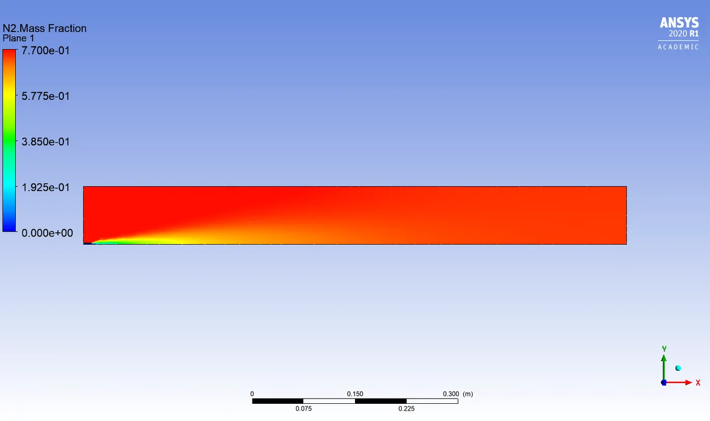
N2 mass fraction
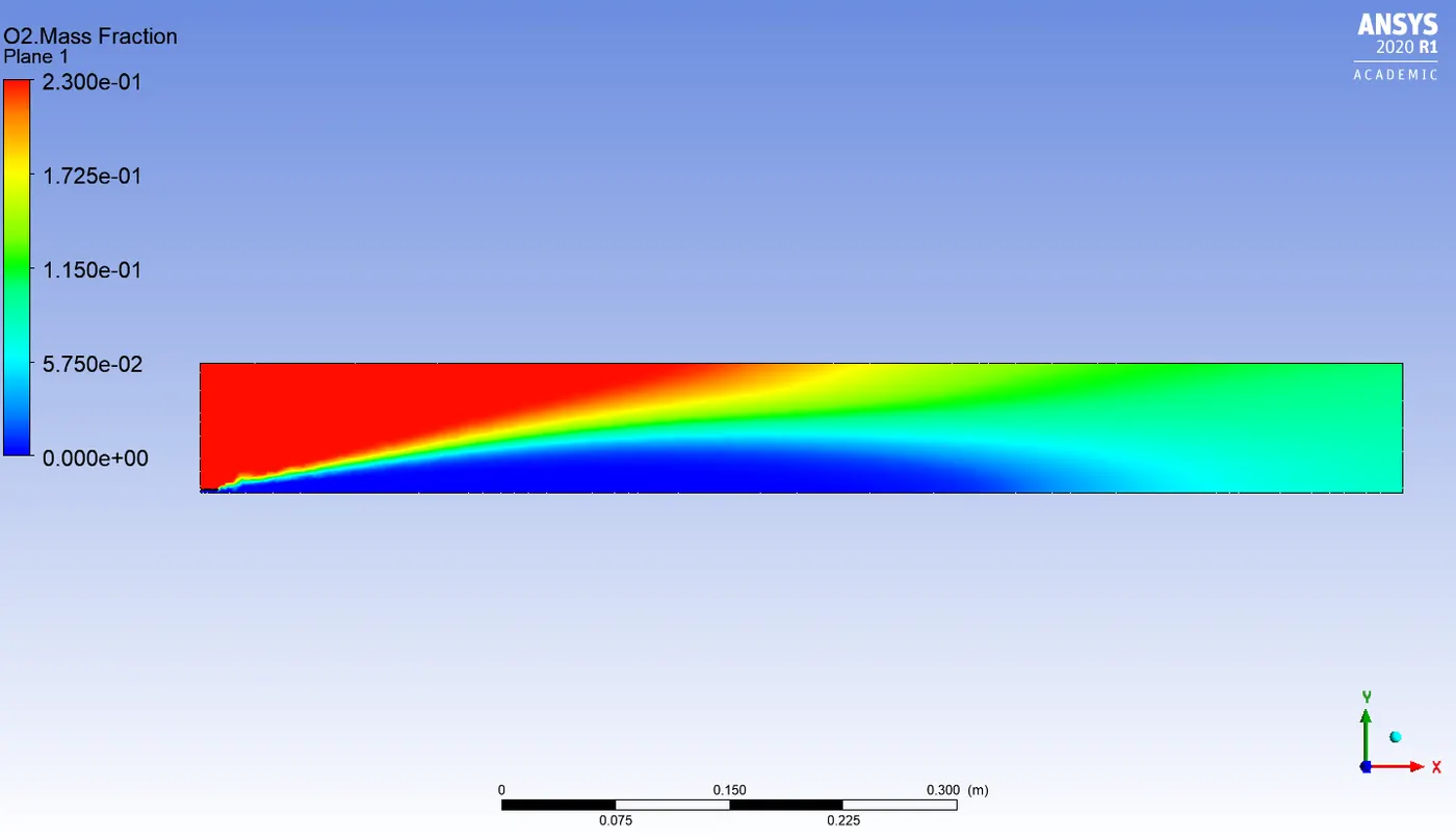
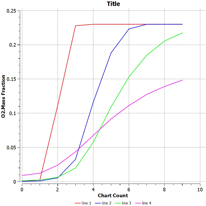
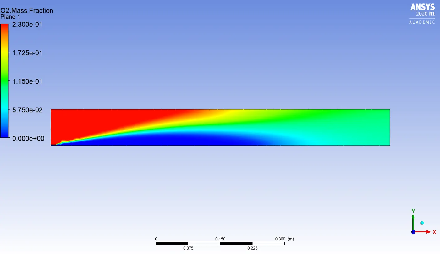
O2 mass fraction
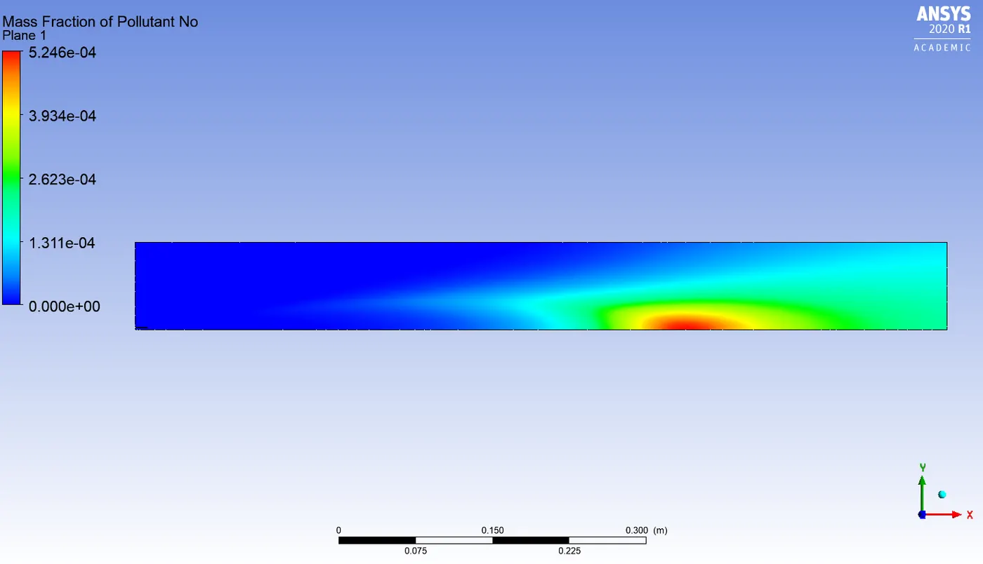
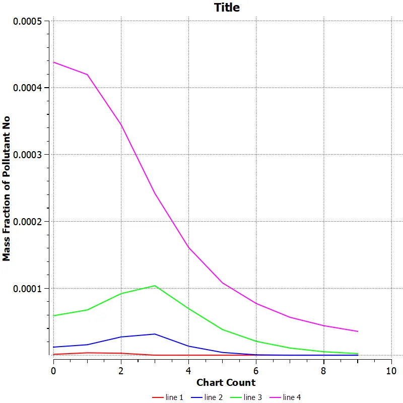
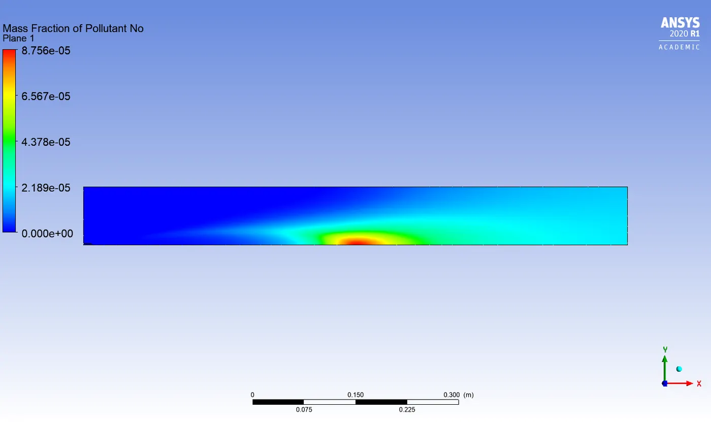
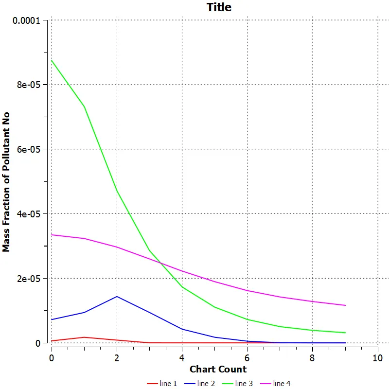
Pollutant NOx mass fraction
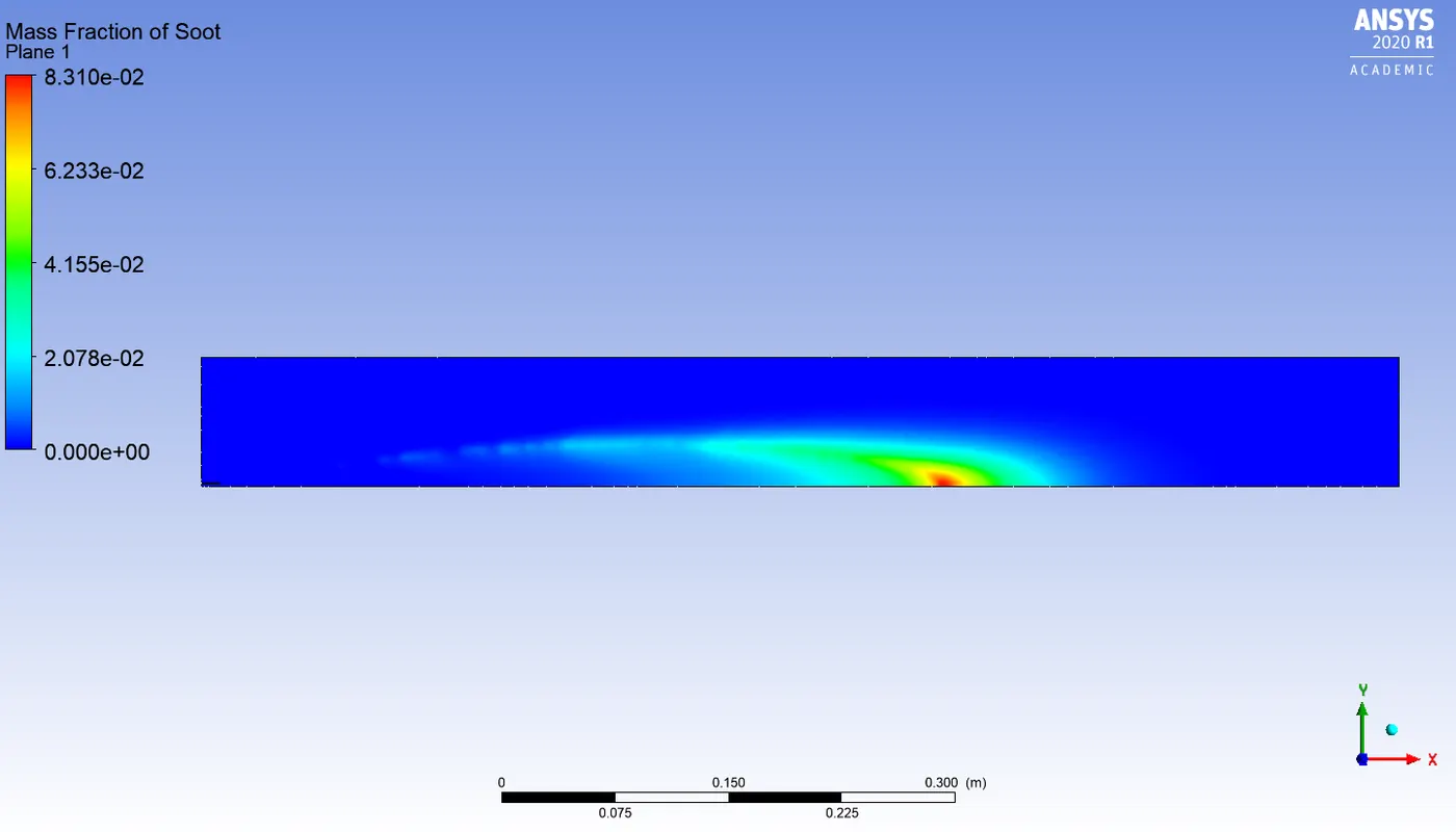
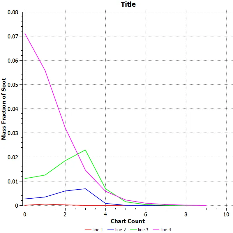
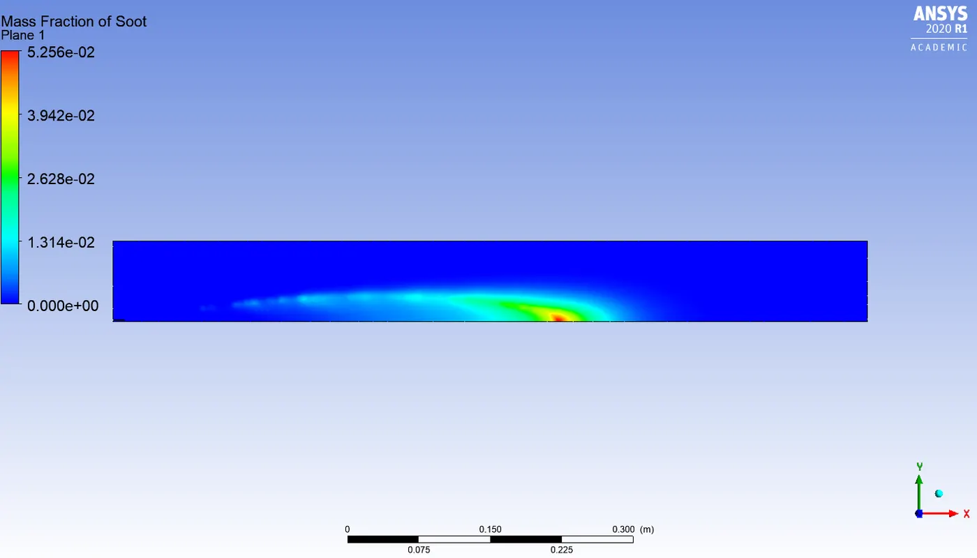
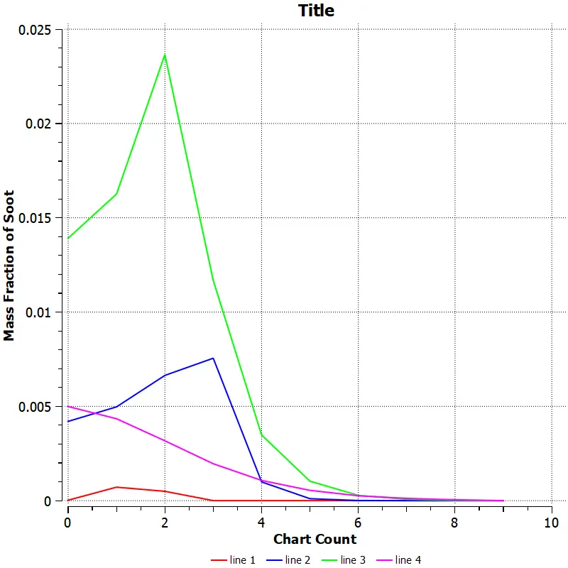
Pollutant soot mass fraction
Observations from part 1 simulation
1. In the temperature contour, it can be seen that the highest temperature is observed ahead of the inlet of combustor where the mixing of fuel-air mixtures takes place.
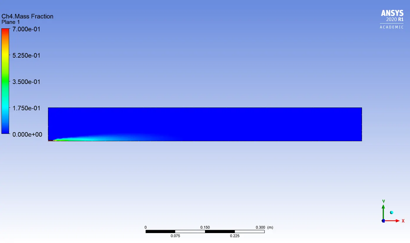
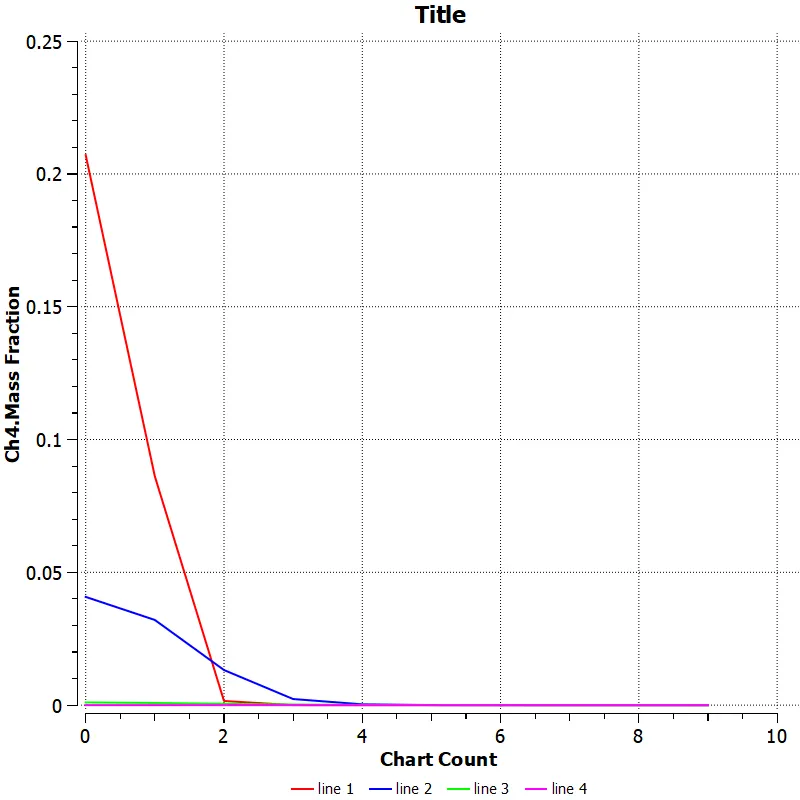
2. In the Ch4 mass fraction contour, the highest mass fraction of Ch4 is observed near the fuel inlet where the fuel is discharged and as combustion takes place Ch4 mass fraction decreases.
3. Highest mass fraction of Co2 and H2o is observed in the high temperature zone.
4. From the N2 mass fraction contour, it can be seen that the N2 is almost distributed uniformly across the combustor.
5. The oxygen mass fraction is highest near the air-inlet.
6. The pollutant like Nox and soot mass fraction is more near the outlet of the combustor.
Results of part 2
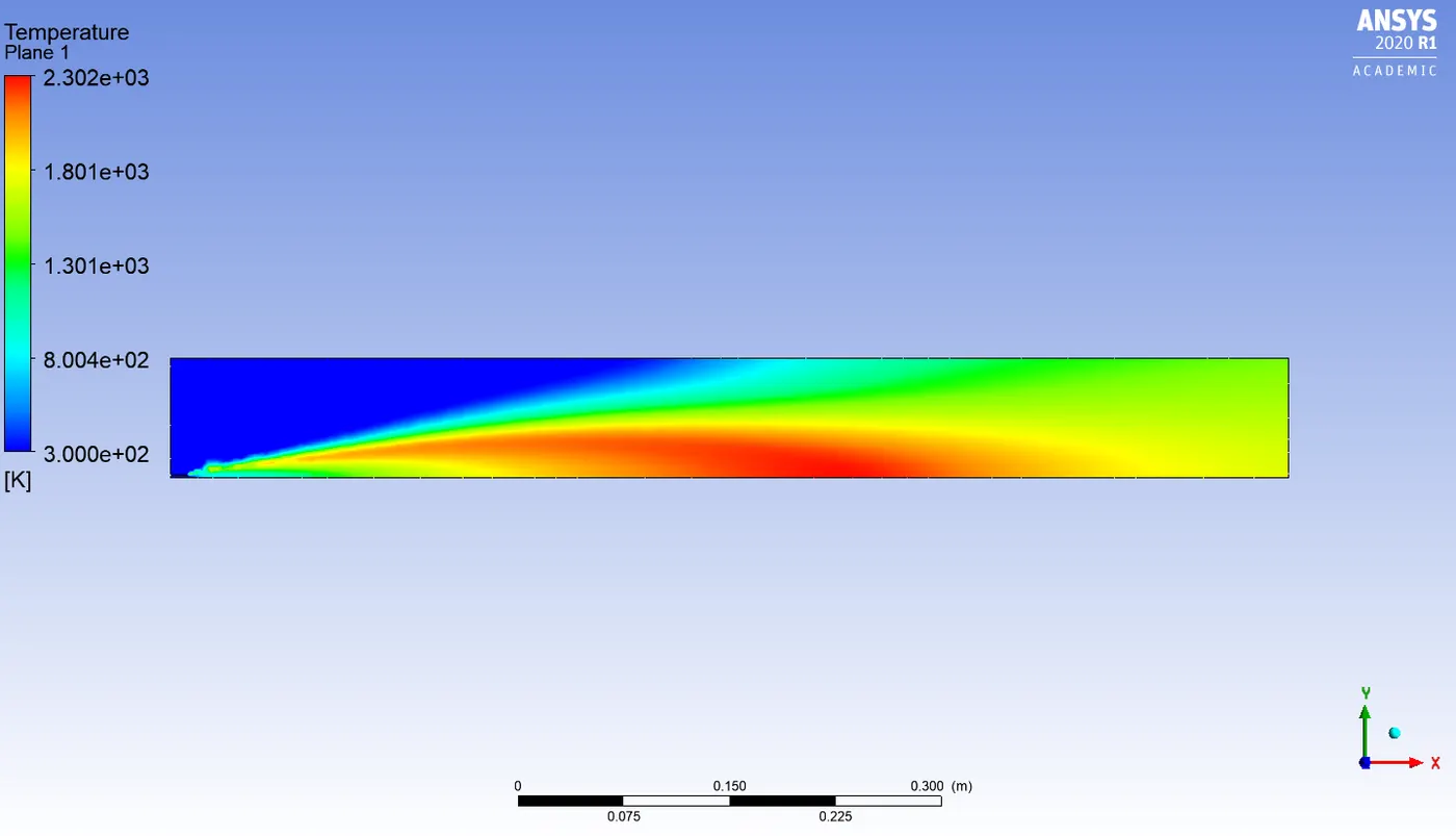
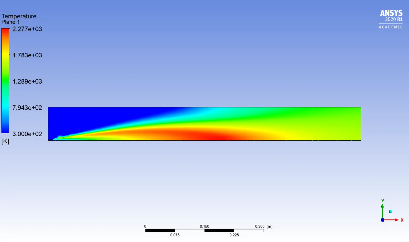
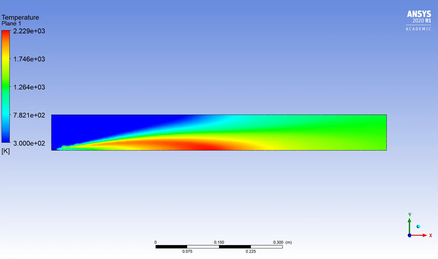
Temperature contour :
5% water content in fuel
15% water content in fuel
30% water content in fuel
Ch4 mass fraction :
5% water content in fuel
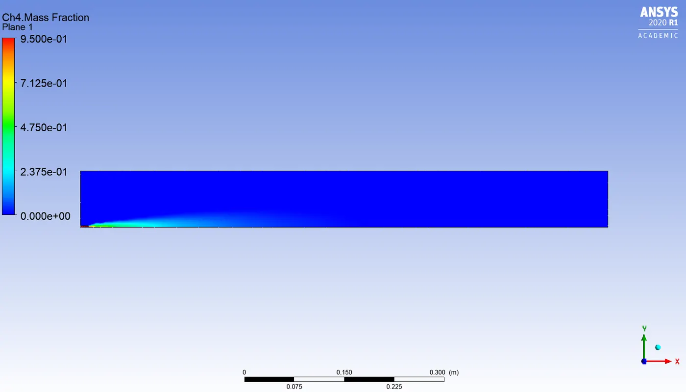
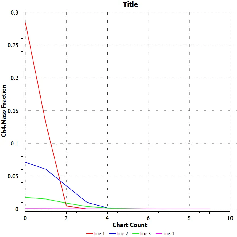
15% water content in fuel
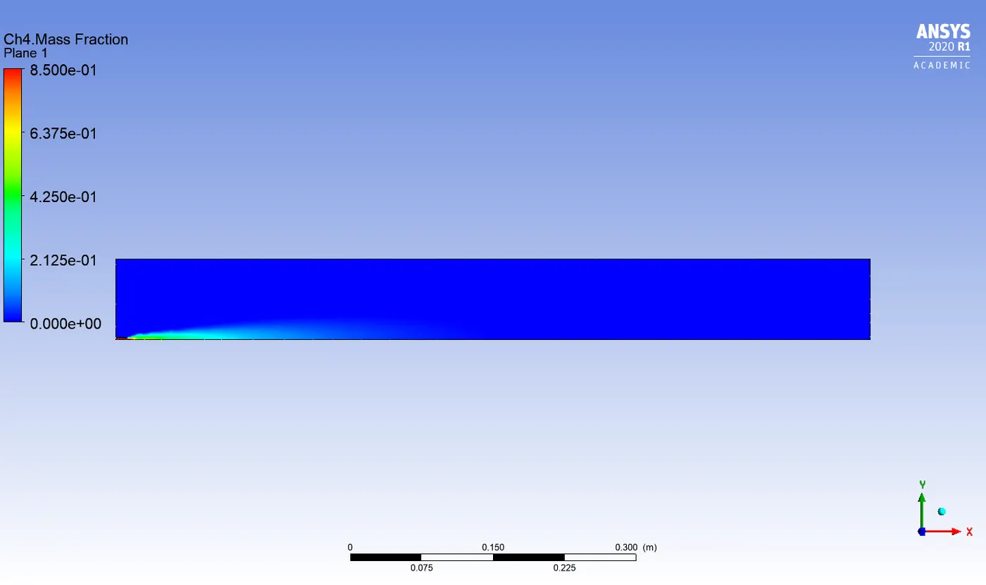
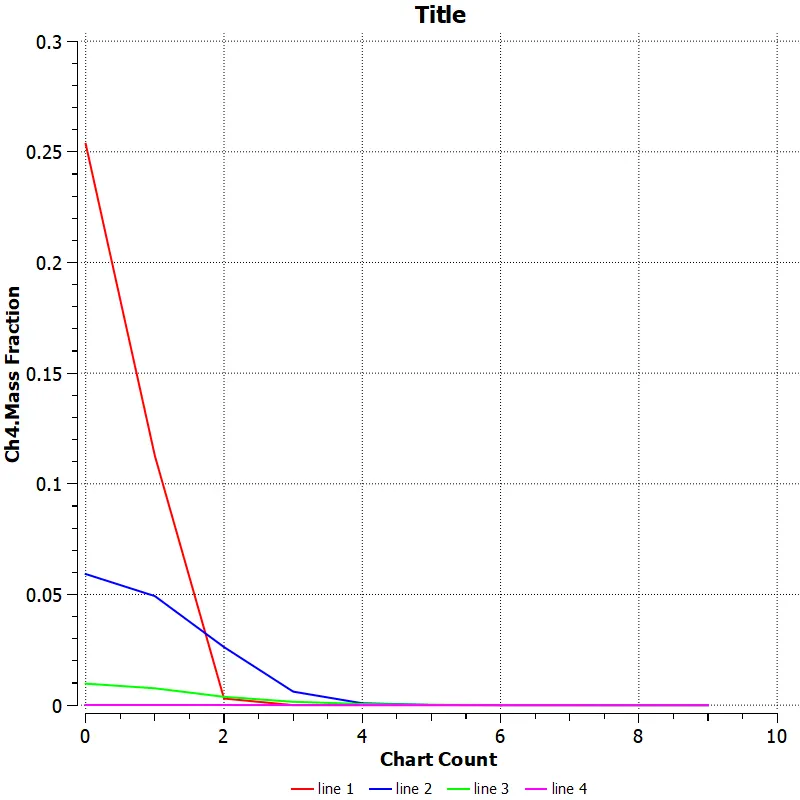
30% water content in fuel
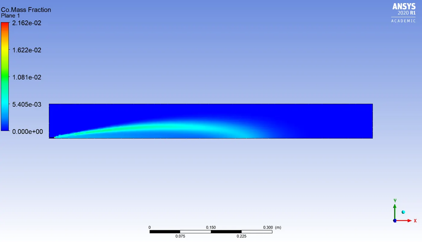
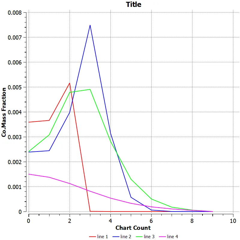
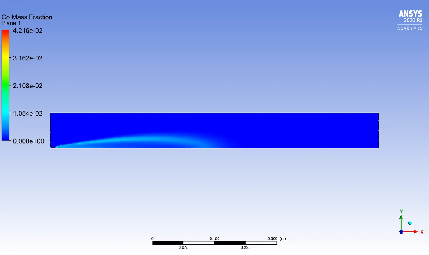
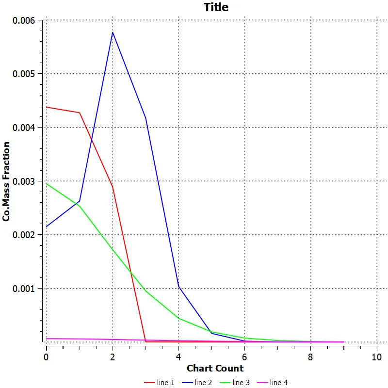
Co mass fraction :
5% water content in fuel
15% water content in fuel
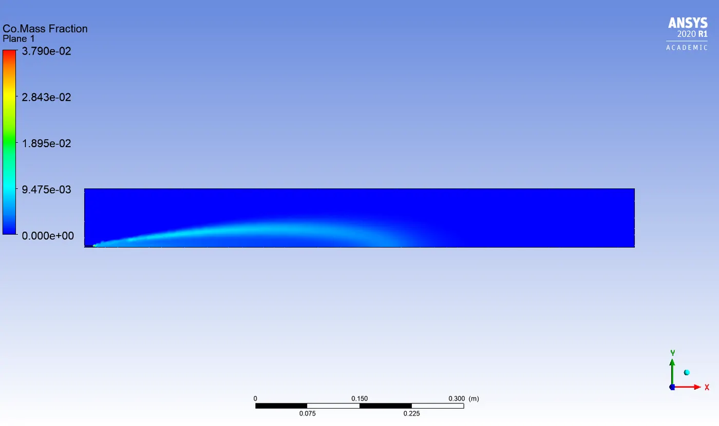
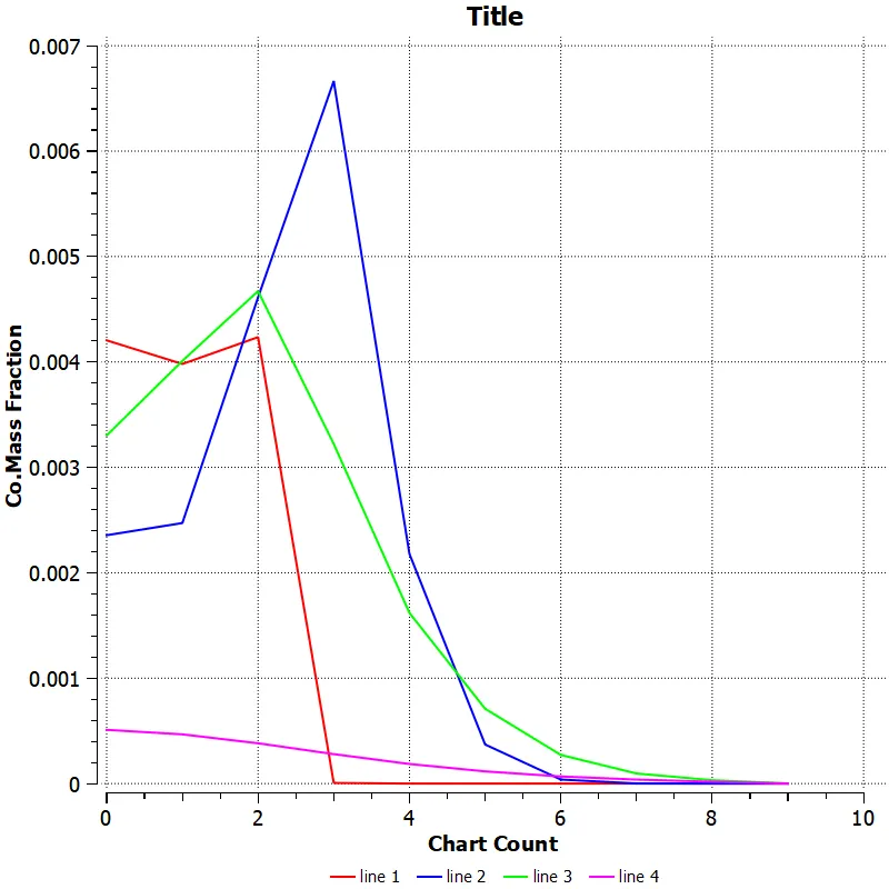
30% water content in fuel
Co2 mass fraction :
5% water content in fuel
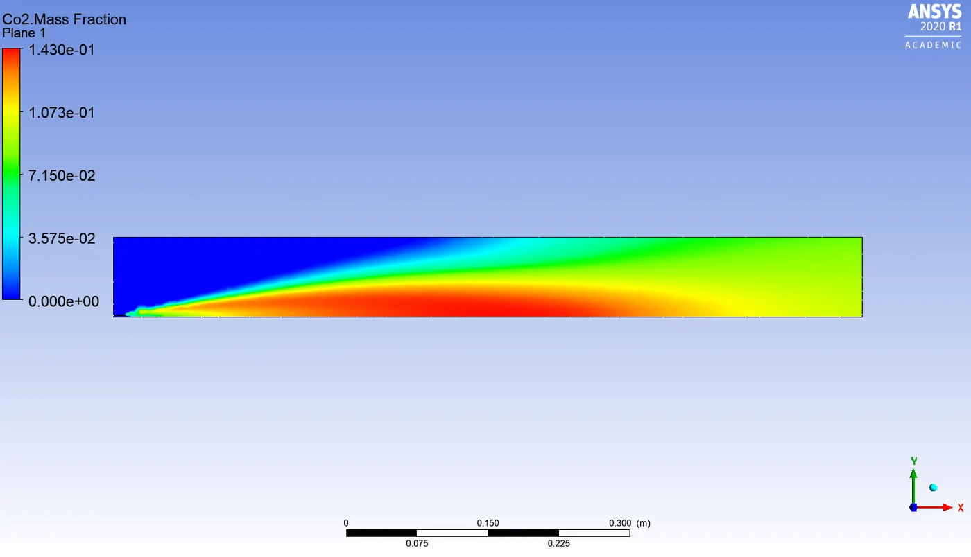
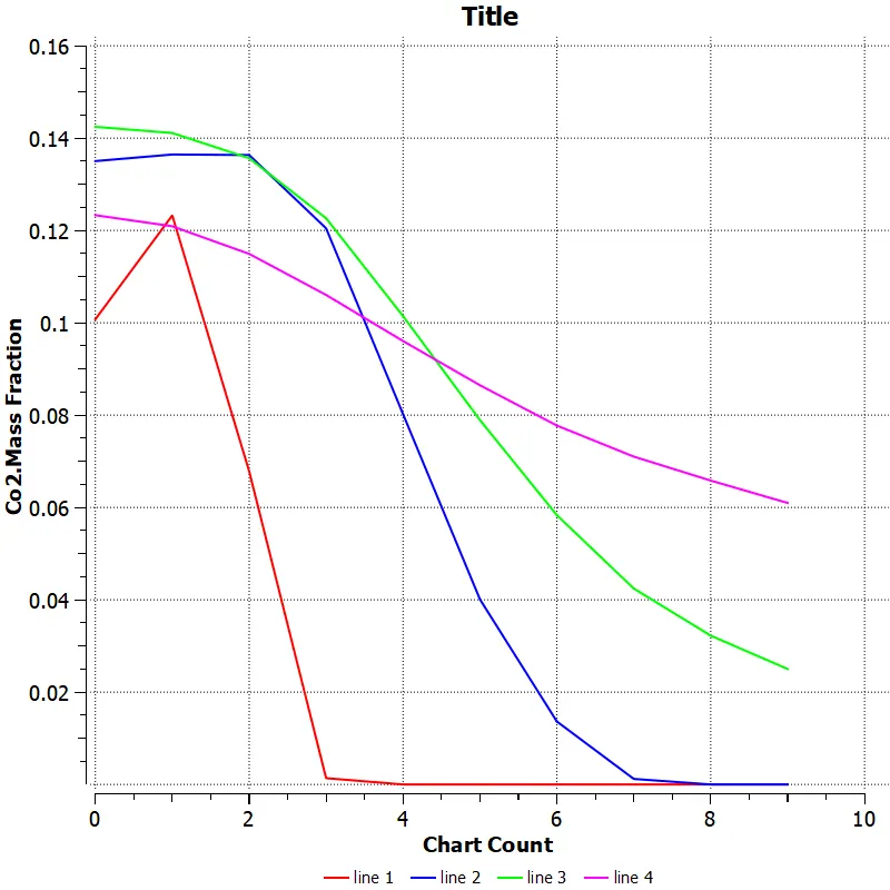
15% water content in fuel
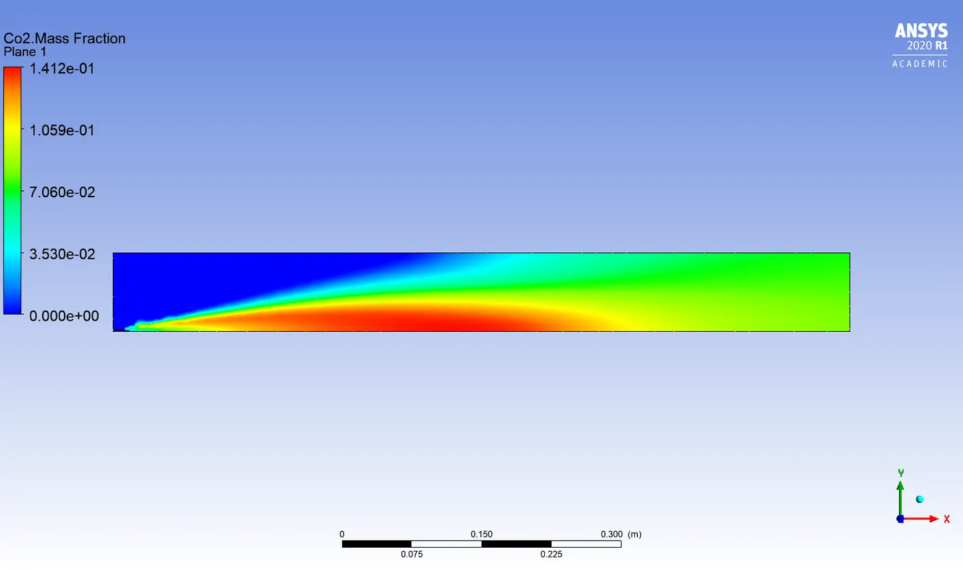
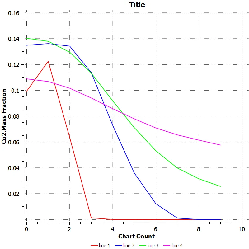
30% water content in fuel
H2o mass fraction :
5% water content in fuel
15% water content in fuel
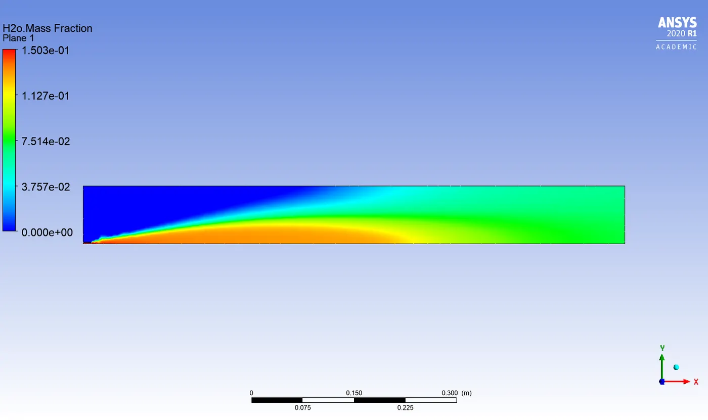
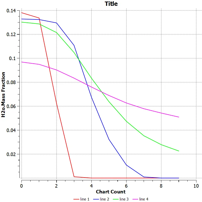
30% water content in fuel
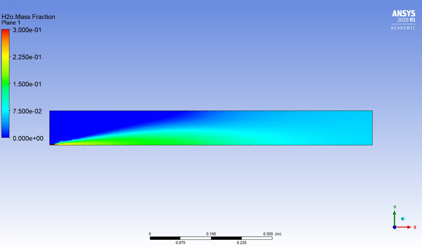
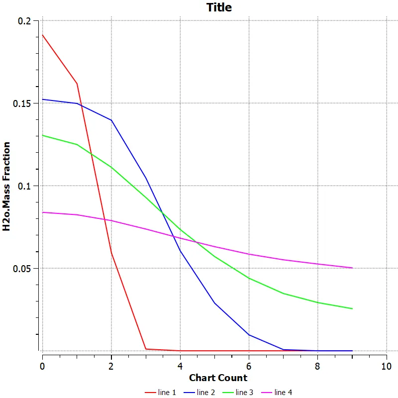
N2 mass fraction :
5% water content in fuel
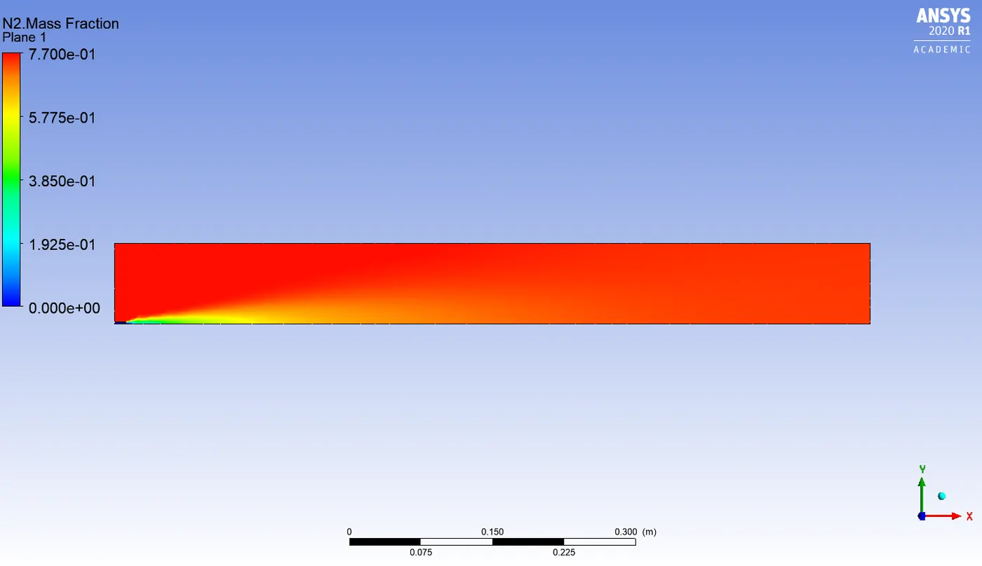
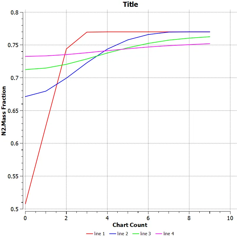
15% water content in fuel
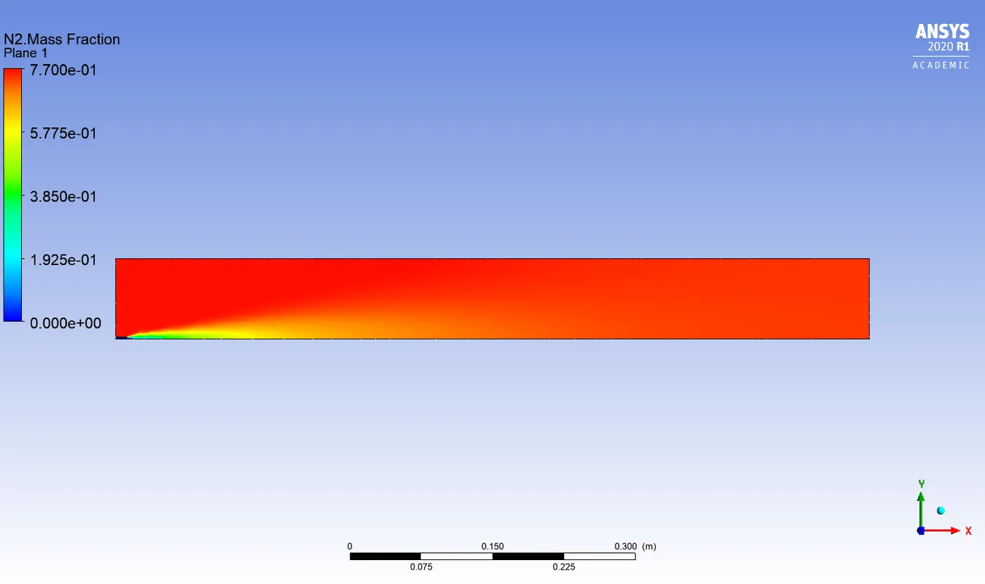
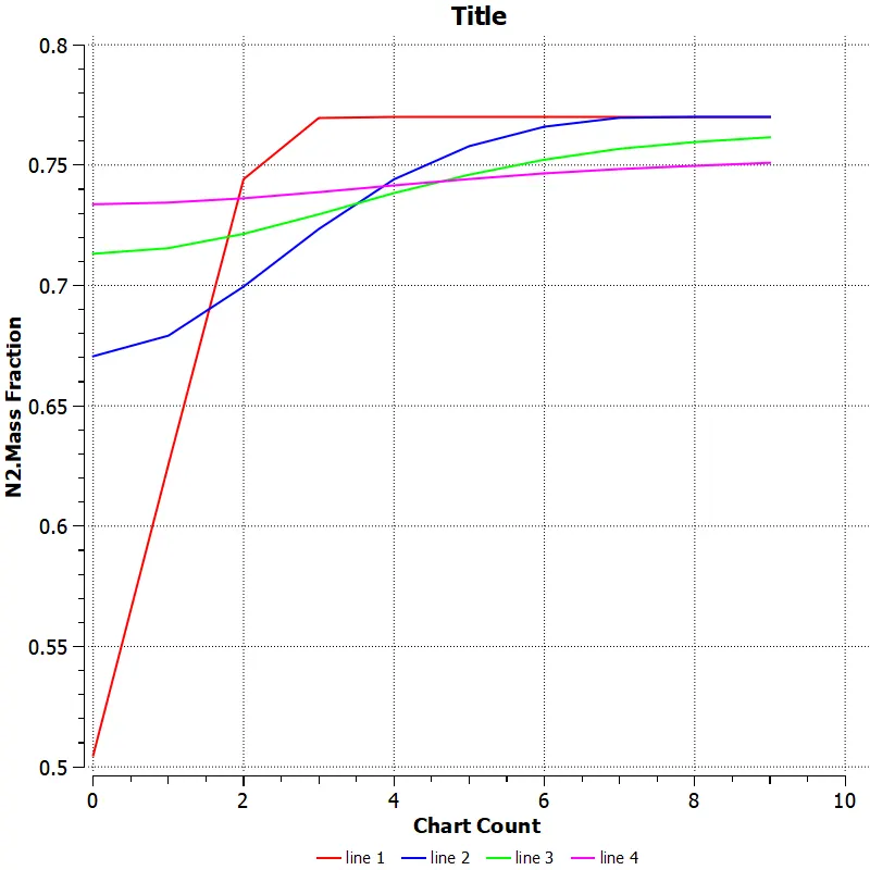
30% water content in fuel
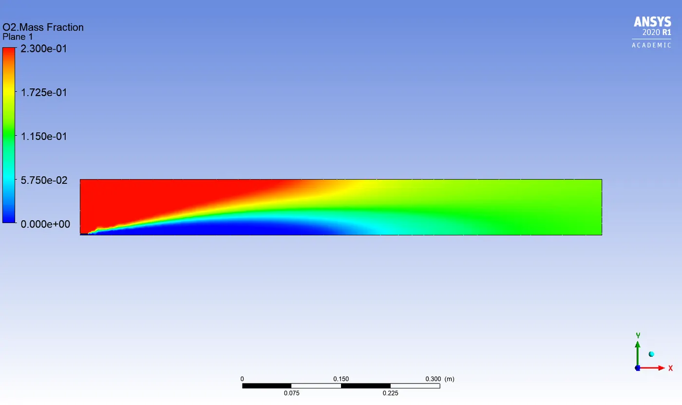
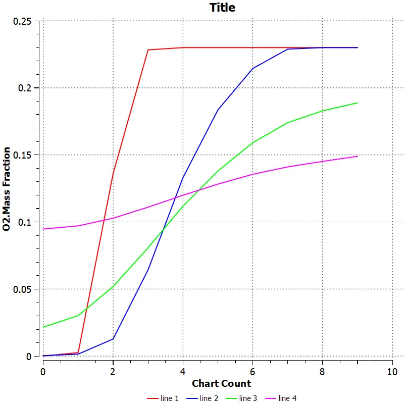
O2 mass fraction :
5% water content in fuel
15% water content in fuel
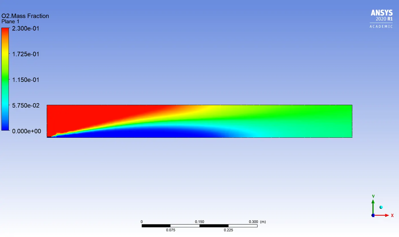
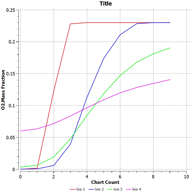
30% water content in fuel
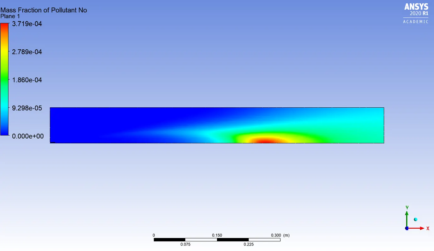
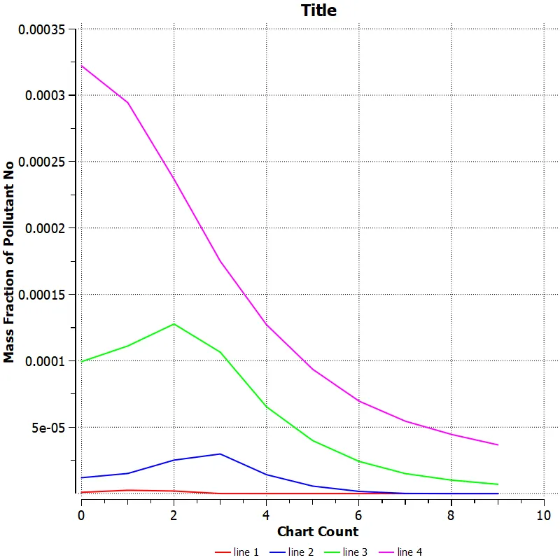
Pollutant NOx mass fraction :
5% water content in fuel
15% water content in fuel
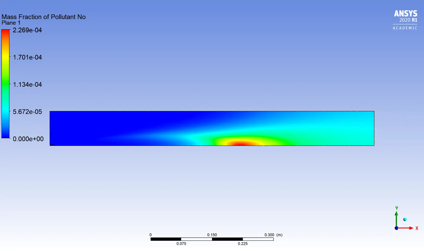
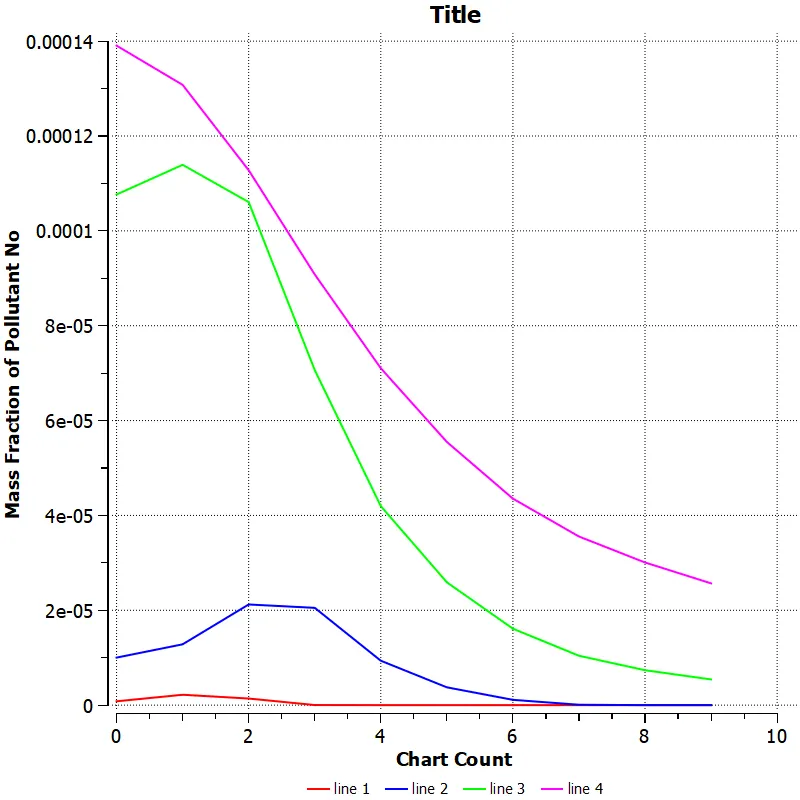
30% water content in fuel
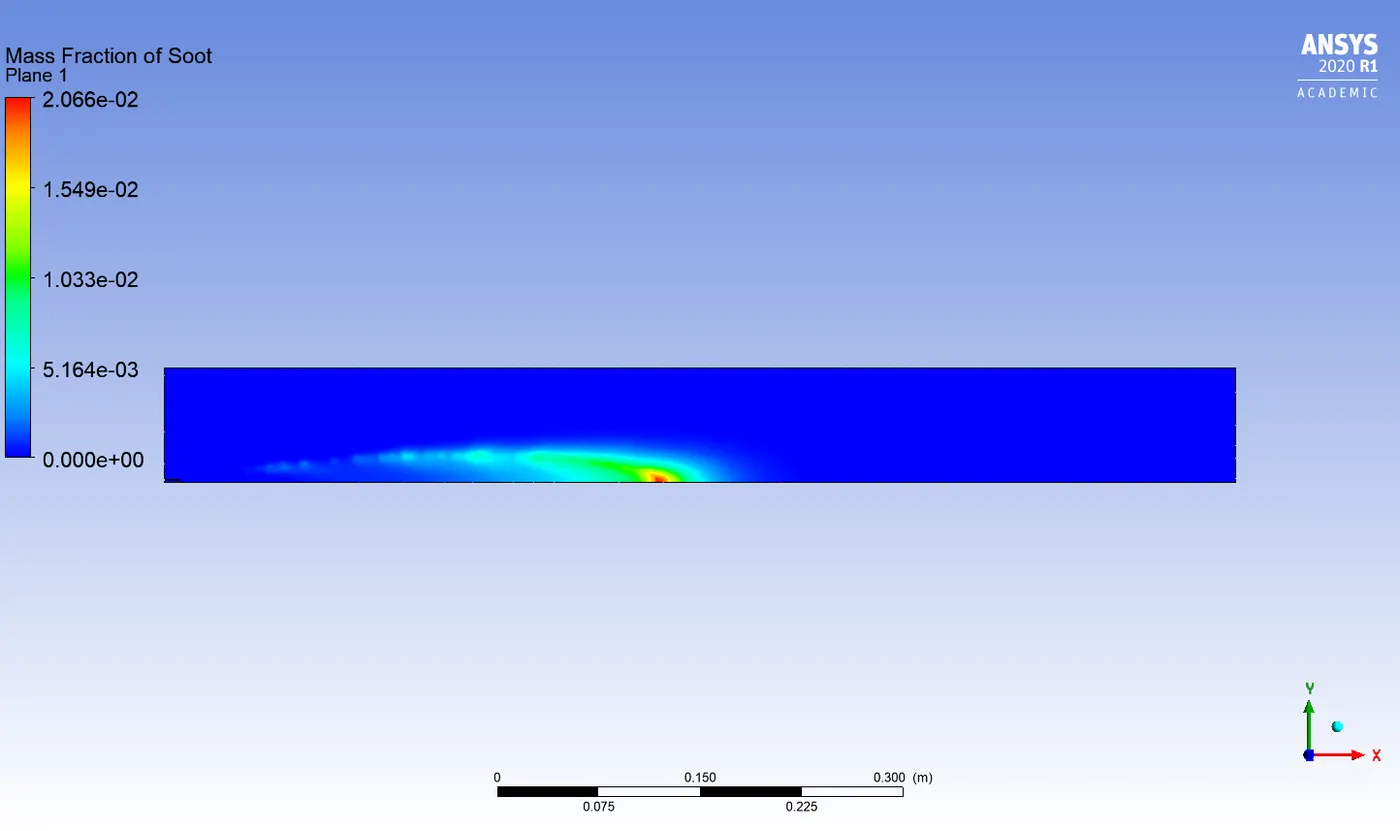
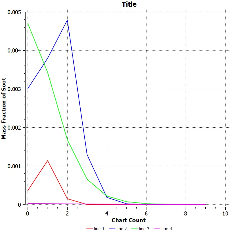
Pollutant soot mass fraction :
5% water content in fuel
15% water content in fuel
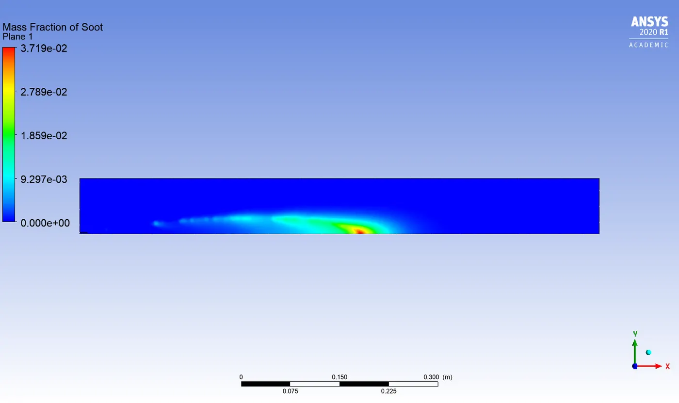
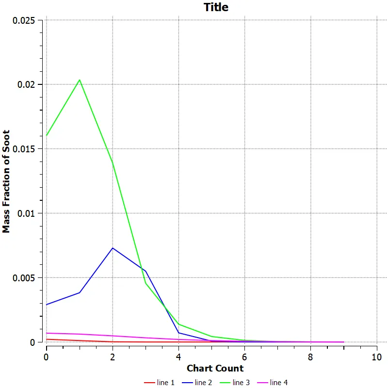
30% water content in fuel
Observation from part 2 simulation
1. The temperature drops from 2302 K to 2229 K as the water content is increased from 5% to 30% in the fuel.
2. The mass fraction of Co increases from 0.02 to 0.04 as the water content is increased in the fuel.
3. No variation of N2 and O2 mass fraction is observed.
4. The mass fraction of pollutants like NOx and soot decreases as the water content in the fuel is increased.
Conclusion
In this project, the mass fraction of pollutants from NOx emission and soot formation is predicted with the help of physical and mathematical models incorparated in the CFD software ANSYS fluent. The results obtained from the simulation shows that the addition of water into the fuel not only decreases the temperature of the combustor but also helps in reducing the mass fraction of pollutants like NOx and soot.
--------------------thank you------------------------------------------------------------