Week 10 - Simulating Combustion of Natural Gas.
WEEK 10: PROJECT DETAILED REPORT
Objectives:
(1) Explain why battery cooling is neededand give a brief description about various techniques for battery cooling.
(2)Perform mesh independance study for any one case and based on your judgment use more suitable model for further cases.
(3) Run the simulation by varying the velocity of air3,5 and 10 m/s and discuss the results.
(4) Find out maximum temperature and heat transfer coefficient obtained by the battery
(5)Based on the results and your judgement select one case(3, 5 or 10 m/s)and vary the spacce between batteries as 2, 4 and 6 mm and discuss the results.
(5)Prove that simulation has acieved convergence with appropriate images and plots(Velocity and temperature contour plots on the cut plane)
(6) Create the animation to observe the temperature distribution and velocity contour
(7) Summarize the results in tabulation/graphical p
form
(7) State the inferences based on the results.
Introduction:
The Need for Battery Cooling Systems in Electric Vehicles
Overheating is one of the major causes that accelerates the rate of battery degradation in electric vehicles. Heat generation makes the battery work hard and causes its performance to deteriorate over time. The direct current fast charging and rapid charging of the battery are not good for battery health, as the accelerated electric currents create higher temperatures.
The high temperature in the battery causes battery fluid evaporation and damage to the internal structure of the battery, which cannot be corrected. At optimal temperatures, discharge power availability, charge acceptance during regenerative braking, and battery health are at their best. The battery life, electric vehicle driveability, and fuel economy degrade as the temperature increases. Considering the overall thermal effect on the battery, a battery cooling system is of great importance in electric vehicles.
Four methods to keep electric vehicle batteries cool
For battery performance and lifespan, keeping the battery pack within the right temperature range is key. We'll tell you more about the different battery cooling methods for electric vehicle batteries that a used and the up and downsides of these methods.
1. Air cooling
By running air through the battery pack batteries can be cooled. For example, Nissan uses this technology to cool the batteries of the Nissan Leaf. They circulate the air from inside the car through the battery pack. With this system the batteries can be cooled but can also be heated during cold winter days. A downside to this system is that the temperature of the air inside the vehicle is also the temperature with which the batteries get cooled. When you turn up the heat inside the car because you are cold, the batteries get heated as well. This is sometimes not ideal, especially when high power is requested.
2. Liquid cooling
Liquid cooling is the most popular way of cooling a battery pack. A liquid cooling system consists of a lot more components then for example an air-cooling system. These components do make it possible to improve the cooling performance by upgrading the components.
Electric vehicle manufacturers like Tesla and Audi use liquid cooling in their battery packs. This cooling system is a separate cooling system which only cools the battery pack, the motor and controller are cooled with a second liquid cooling system because of the temperature differences between the components.
3. Cooling with heat conducting materials
Heat conducting materials, such as heat pipes can be used to withdraw heat from the battery pack. This is a slower way of cooling the batteries then when using liquid cooling. Also, metals like aluminum and copper are heat conducting materials. Unfortunately, this way of cooling is only one part of the cooling system instead of a complete one. When using this as the only cooling system, the heat conducting material needs to be very large. The heat conducting material has a certain heat capacity. This is the amount of heat that a material can absorb per weight of the material.
4. Submersion cooling
Another way of cooling a battery pack with liquid is to submerge the complete battery pack in the cooling fluid. This technology is already used in the world of supercomputers. However, this method is very expensive.
Another downside is that the amount of fluid used has a certain heat capacity. As explained before, this is the amount of heat that a material can absorb. By submerging the entire battery pack in a fluid, the fluid can only cool as much as the heat capacity allows it to.
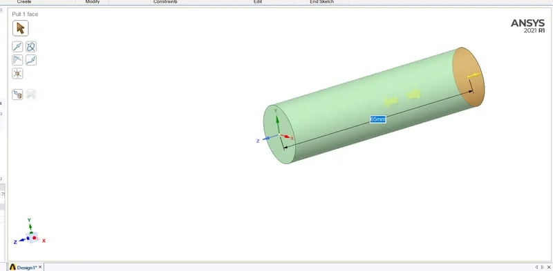
One cylinder created in spaceclaim
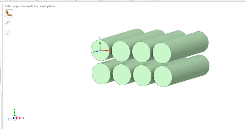
Battery module created as per requirment
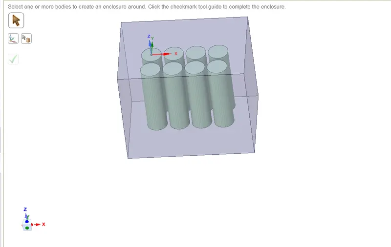
Enclosure created
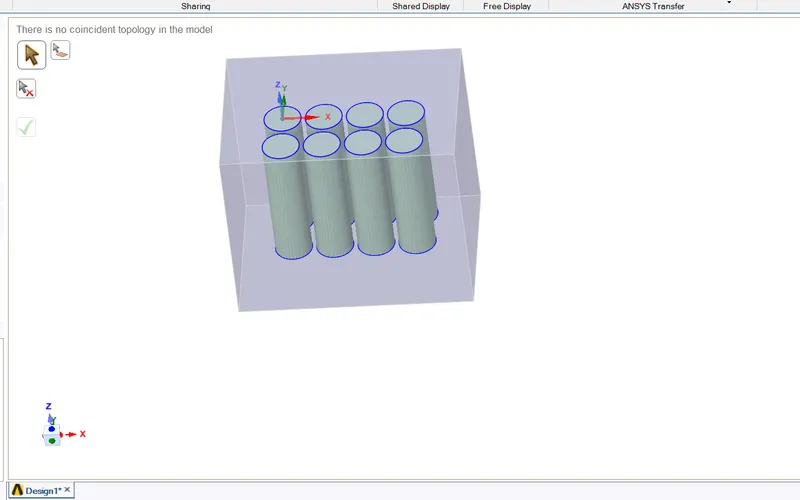
Done share topology
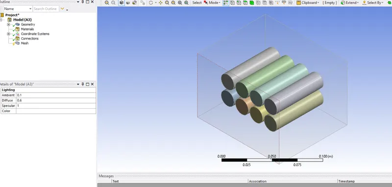
Opened in mesh window
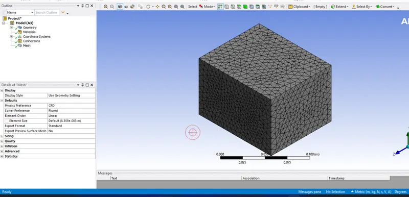
Meshing done with default mesh
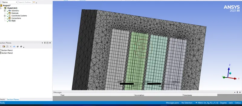
Constructional view-Multizone mesh created

Naming Given
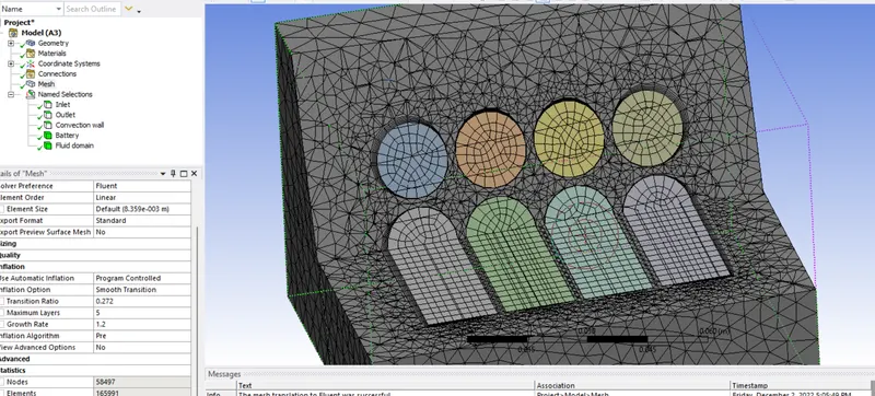
Inflation layer added
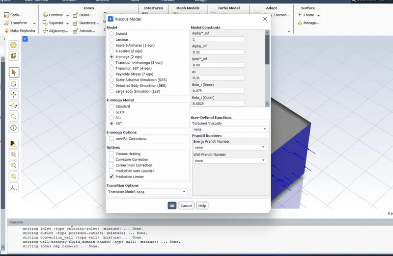
Turbulence model given
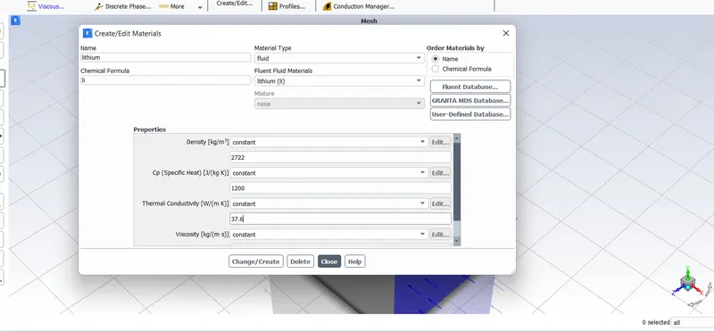
Material added
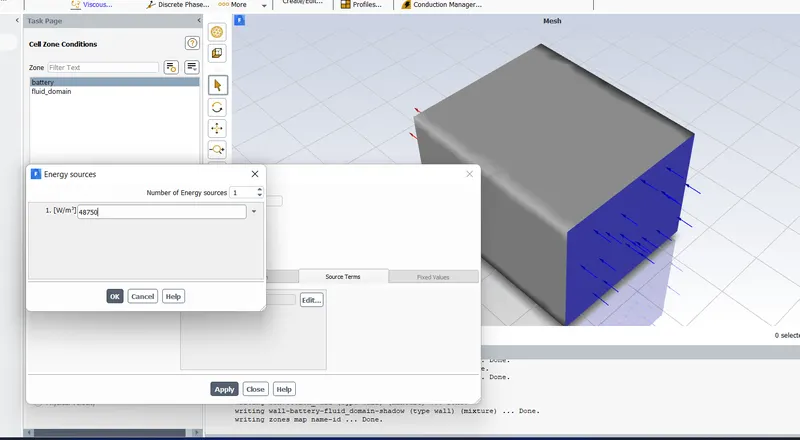
Adding heat source

Giving convection heat transfer coe as 5W/m2K
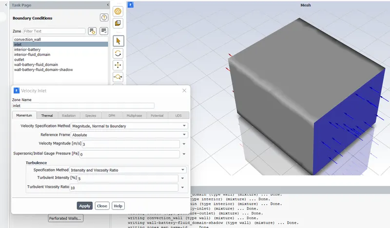
Giving inlet velocity as 3m/s
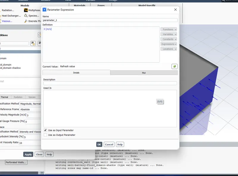
Giving input parameter


Creating htc as output parameter.

Creating maximum temperature as output parameter.
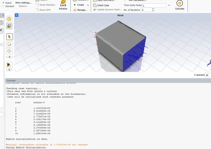
Hybrid Initialization done
RESULTS AND DISCUSSIONS:
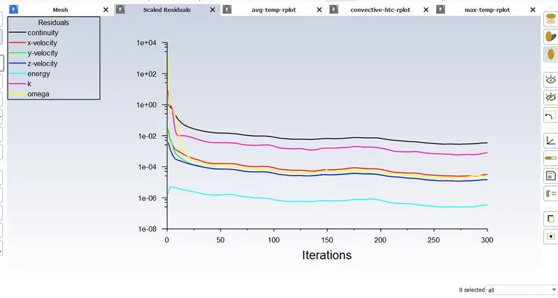
Residulas
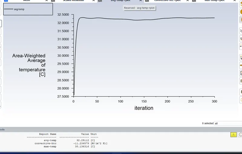
Plot for average temeperature
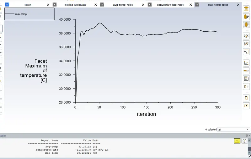
Plot for maximum temeperature
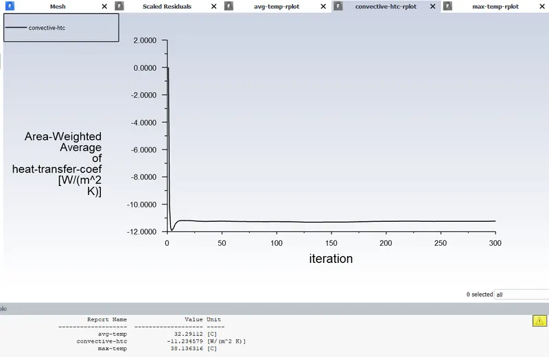
Plot for htc
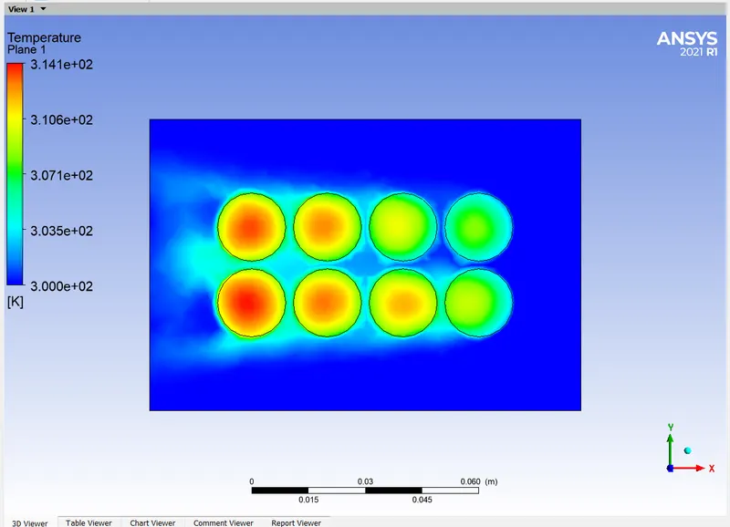
Temperature contour
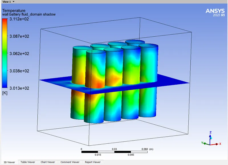
Temperature contour
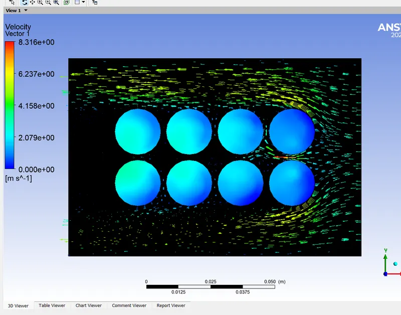
Velocity vector
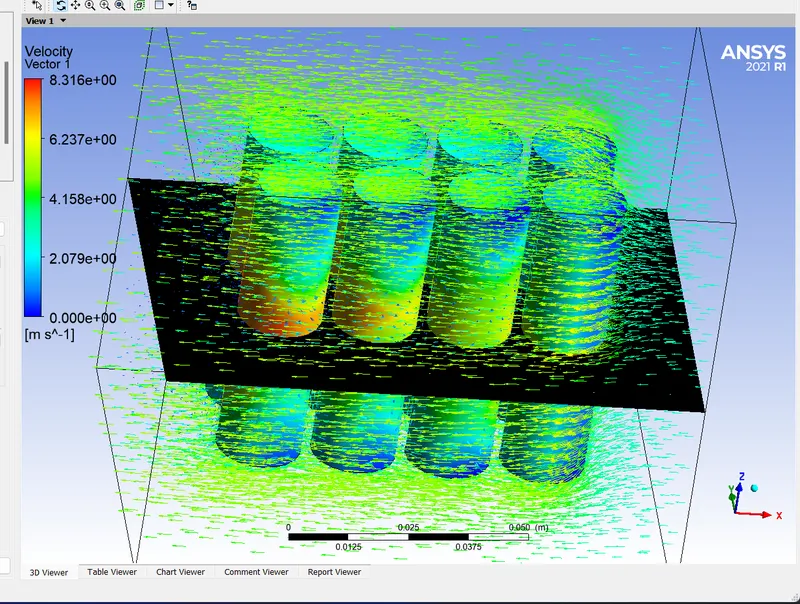
Velocity vector for whole domain
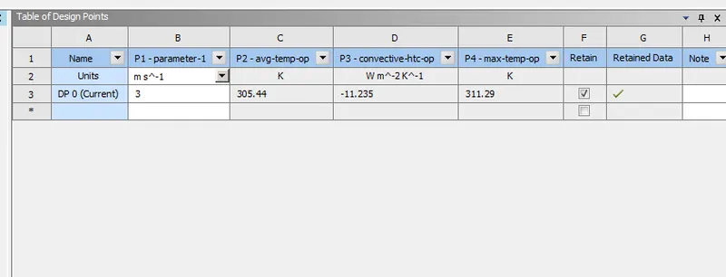
Outputs are showing in parameter set
Note:Video for this case uploaded below
Mesh Independnce study:
| Mesh Size | Cell Count | Average Temperature(K) | Maximum Temperature | HTC(W/m2K) |
| 0.008mm | 1,65,991 | 305.44 | 311.29 | -11.235 |
| 0.005mm | 1,72,408 | 305.41 | 312.23 | -11.25 |
| 0.003mm | 2,35,713 | 305.32 | 312.25 | -11.298 |
From this mesh independance study we can see that there is no much variation in the properties here.So we are sleceting 0.005mm mesh size for the future simulations.
Case 2:(5m/s, 2mm gap)
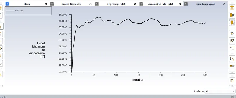
Maximum temperature plot
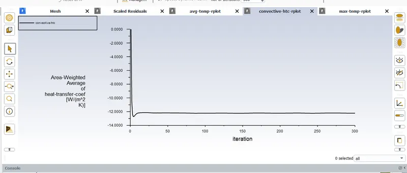
HTC Plot
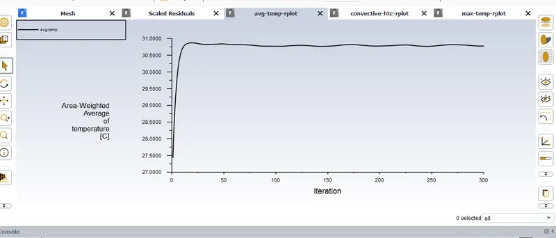
Average temperature plot

HTC as -12.W/m2K
Average temperature is 303.93K
Maximum temperature is 308.89K
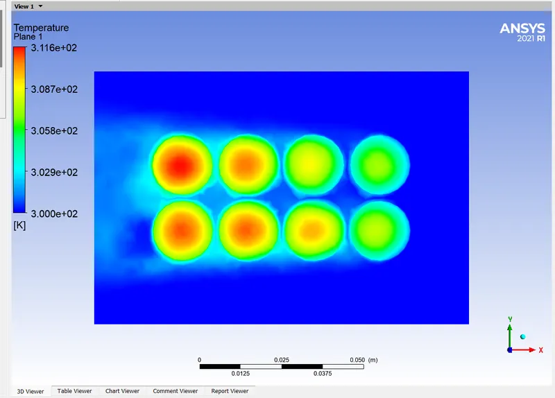
Temperature contour
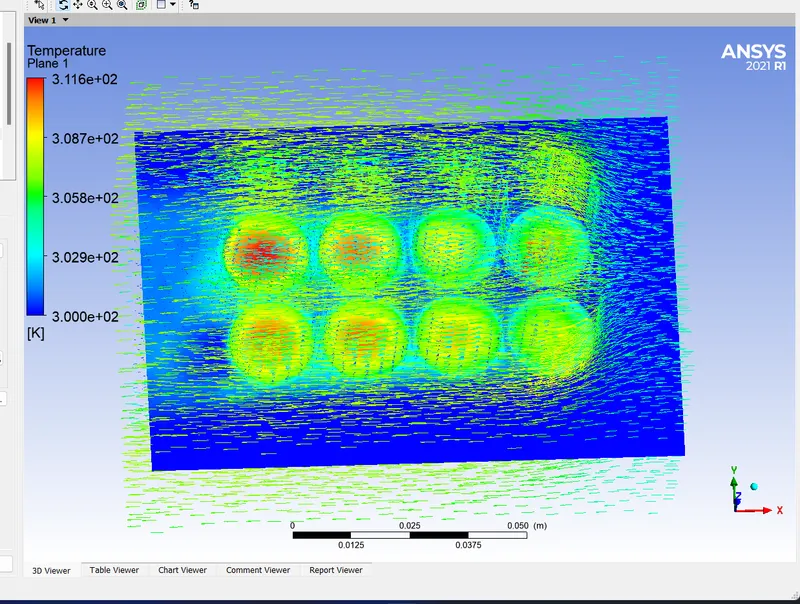
Velocity vector
Case 3: 10m/sec, 2mm gap
RESULTS AND DISCUSSIONS:
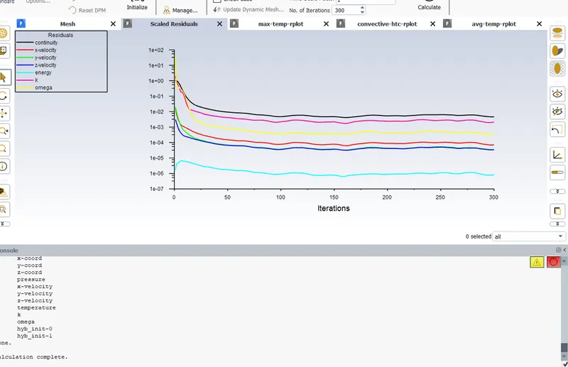
Residulas
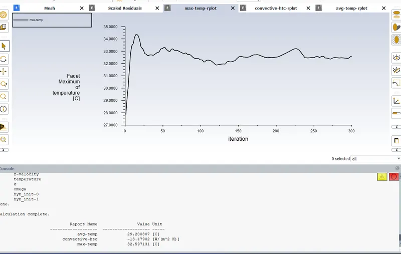
Maximum temperature plot
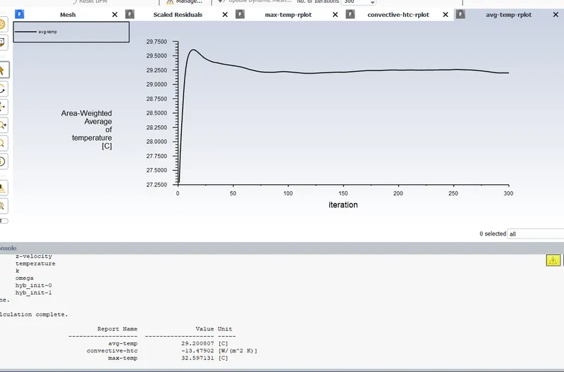
Average temperature plot
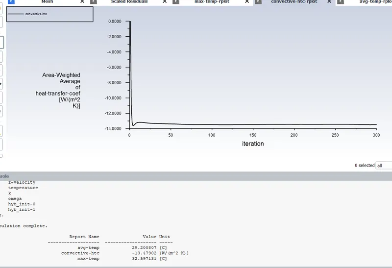
HTC Plot
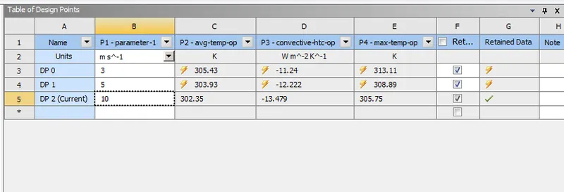
Results in parameter set
From this it is clear that,
HTC =-13.479 W/m2K
Maximum temperature = 305.75 K
Average temperature = 302.35 K
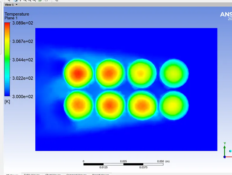
Temperature contour
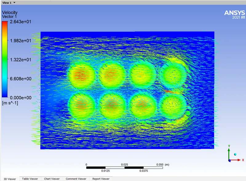
Velocity vector
Case 4: 5mm gap,5m/sec
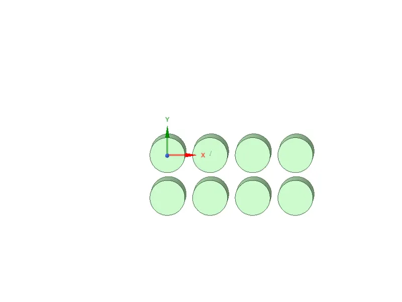
Batteries are arranged bwith 5mm gap
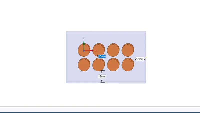
Enclousre made
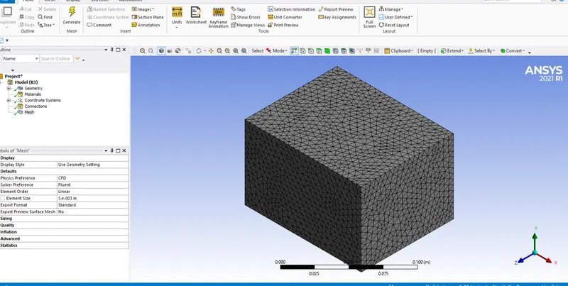
Meshing done with 5mm mesh size
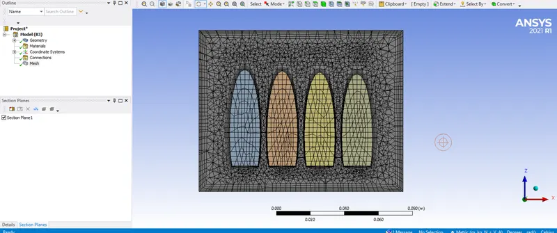
Program controlled inflation layers added
RESULTS AND DISCUSSIONS:
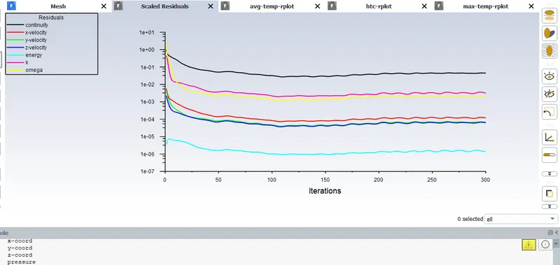
Residuals
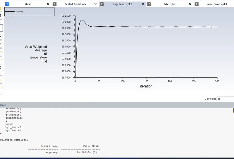
Showing average temperature plot
ie Average temperature is 301.79K
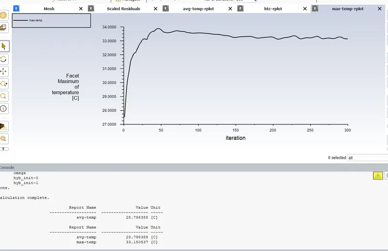
Showing maximum temperature plot
ie maximum temperature is 306.15K
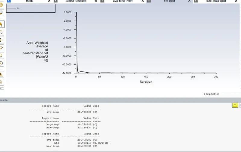
Showing HTC plot
ie HTC is -13.923 W/m2K
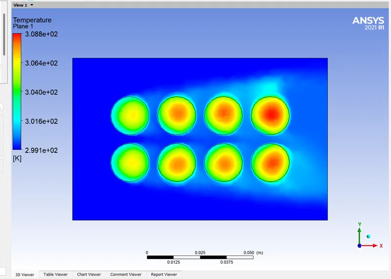
Temperature contour
From this it is clear that ,when the gap between cells increases, the rate of heat transfer also increases and more heat is extracting from the battery.
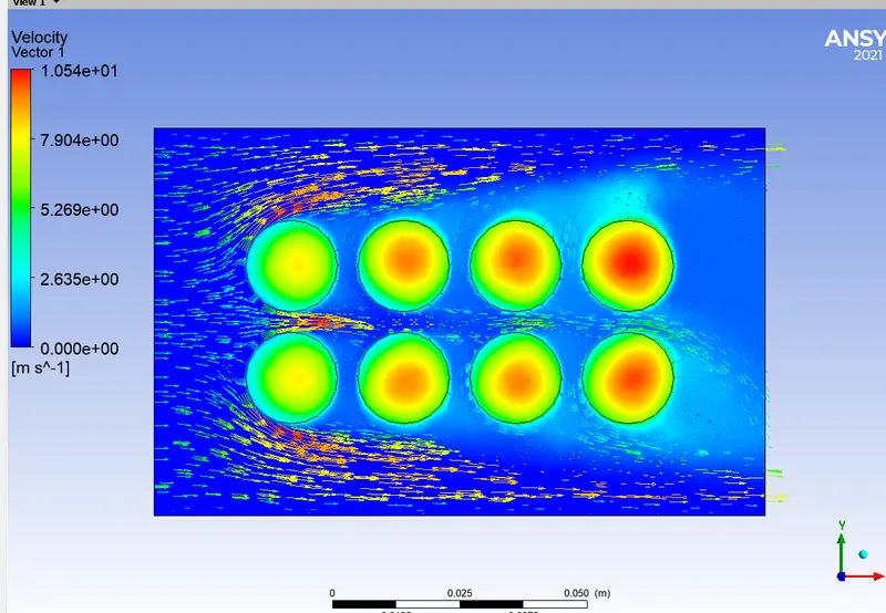
Velocity vector
From this we can see that for the air flow more gap is available and so that more extraction of heat is possible here
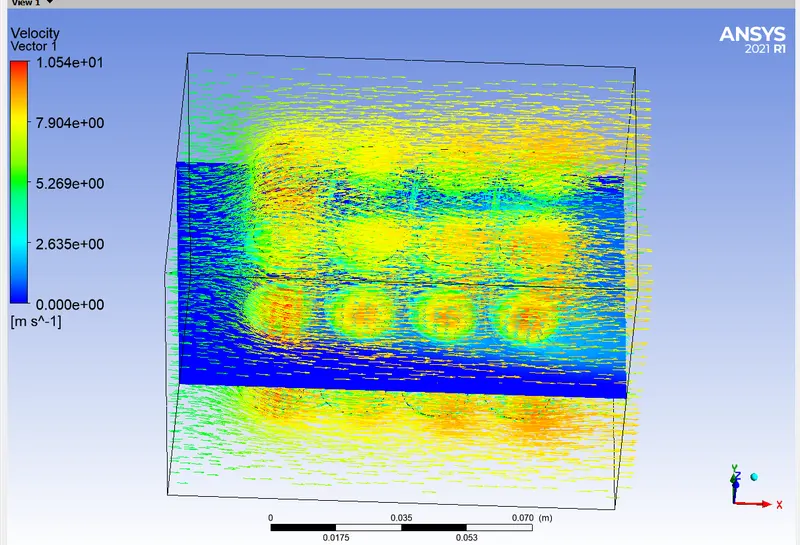
Velocity vector in whole domain
Note: Video for this case uploaded below
Case 5: 6mm gap, 5m/sec
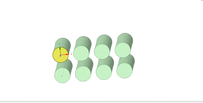
Batteries created with 6mm gap
RESULTS AND DISCUSSIONS:
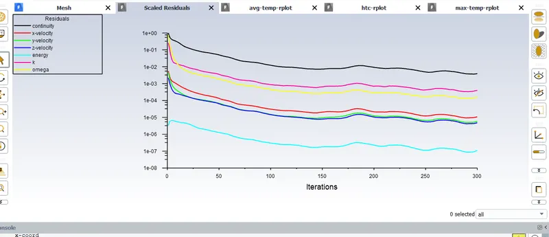
Residuals
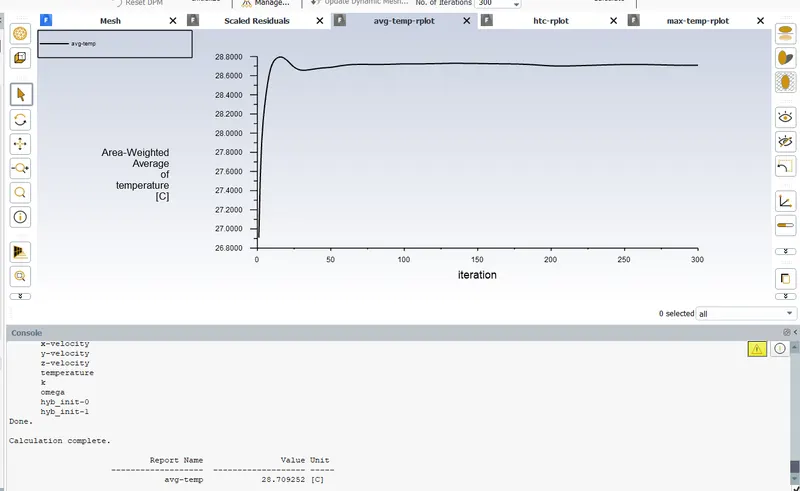
Average temperature plot
Here, average temperature = 301.709 K
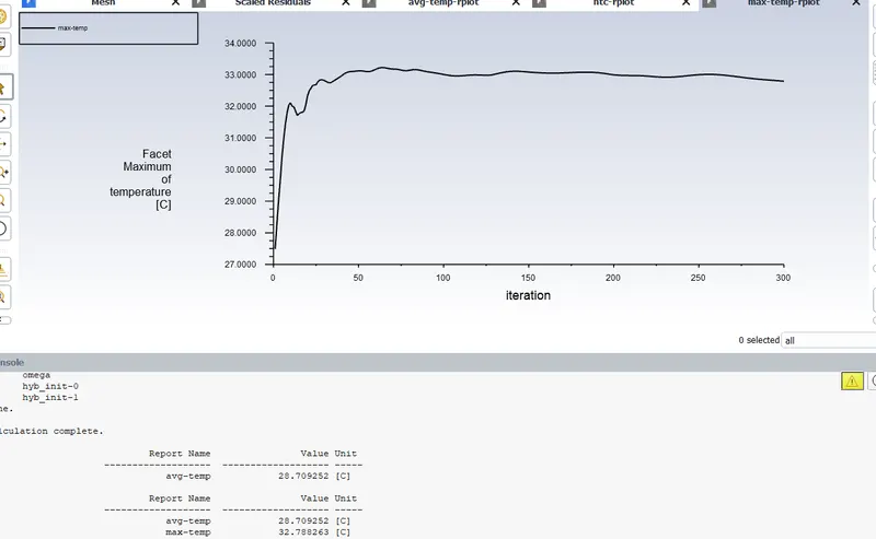
Maximum temperature plot
Here, maximum temperature = 305.788 K
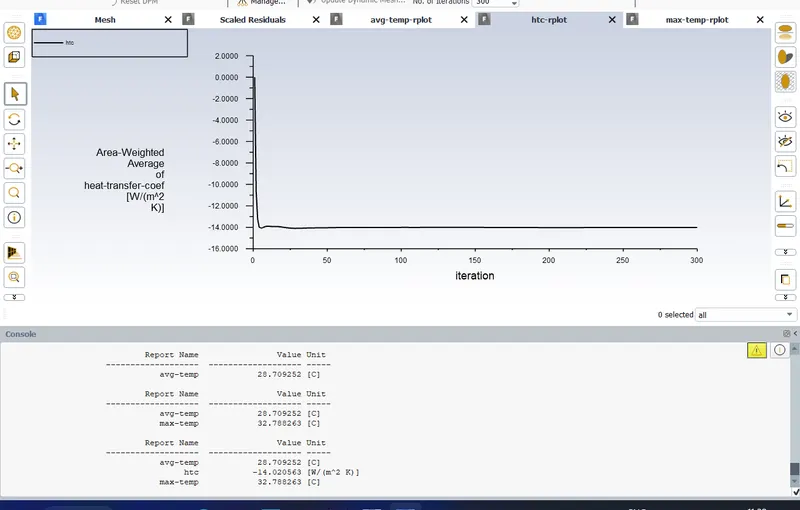
HTC Plot
HTC = -14.020 W/m2K
From this it is clear that when the gap between cells increases the rate of heat transfer also increased as a result average temeperature and maximum temperature decreased. HTC is increased
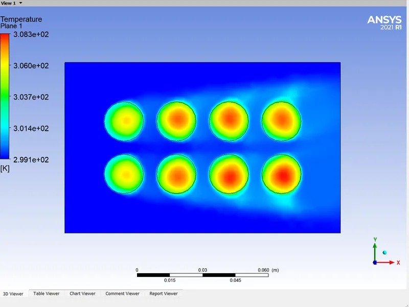
Temperature contour
More heat is transferring due to high air flow
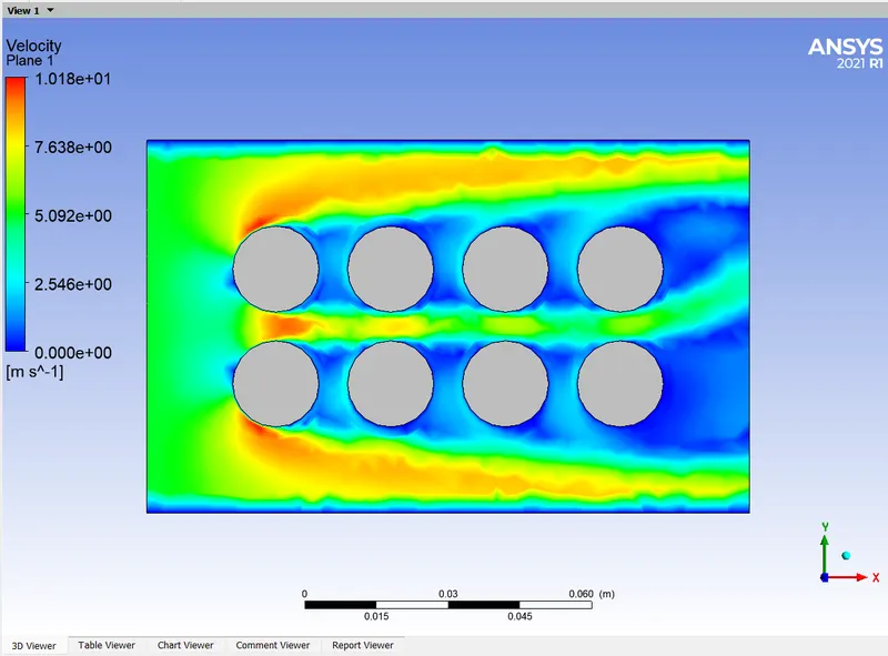
Velocity contour
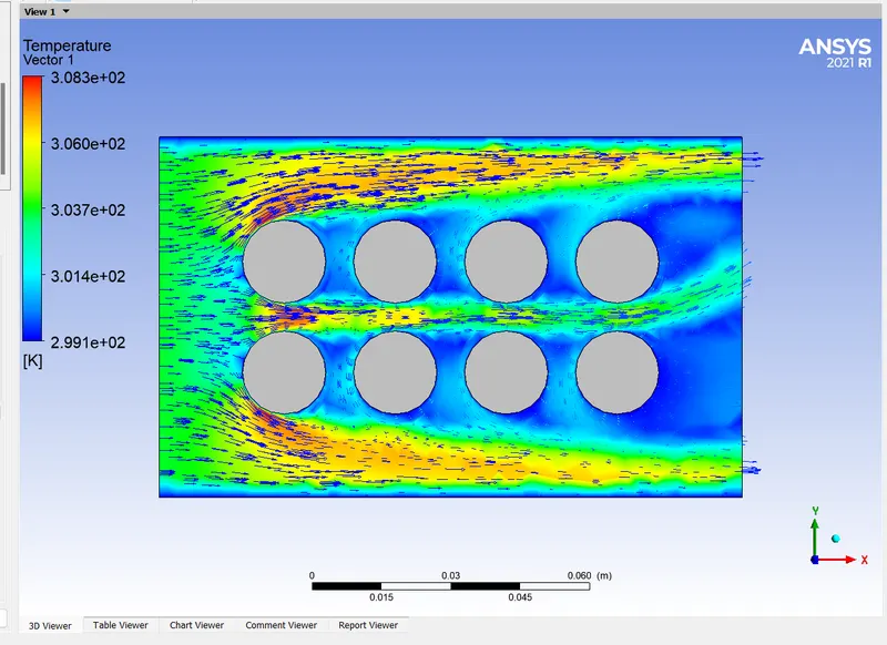
Velocity vector plot
Note: Video for this case uploaded below
Case 6: Air flow in lateral direction, 6mm gap, 5m/sec
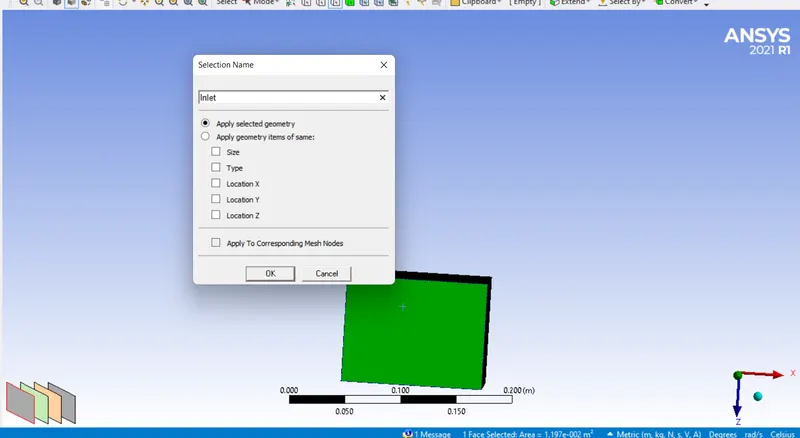
Giving inlet
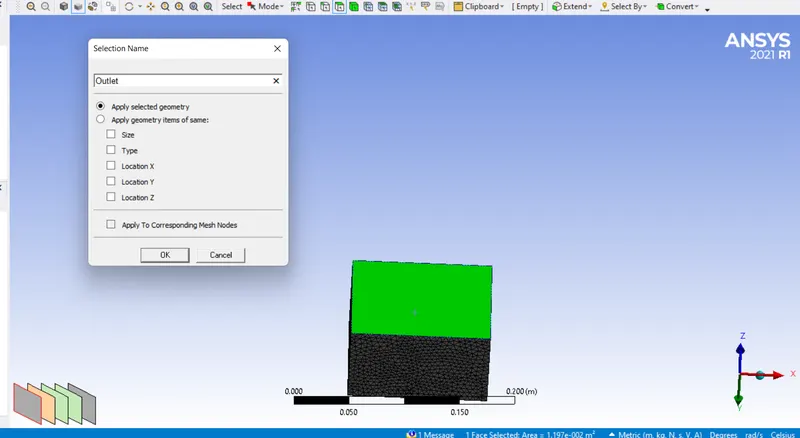
Giving outlet
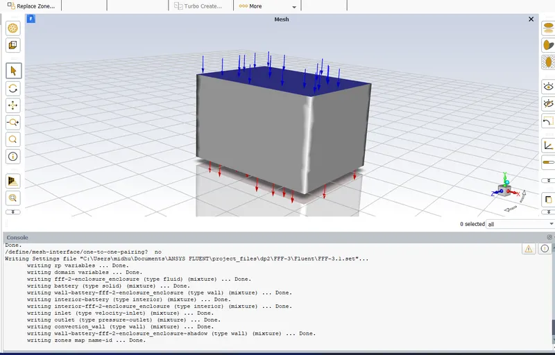
Showing inlet and outlet
RESULTS AND DISCUSSIONS:
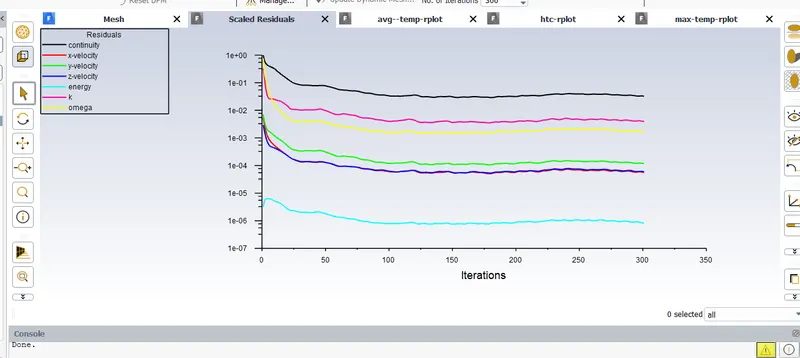
Residuals
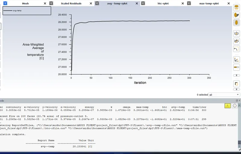
Average temeperature plot
Average temperature = 301.233K
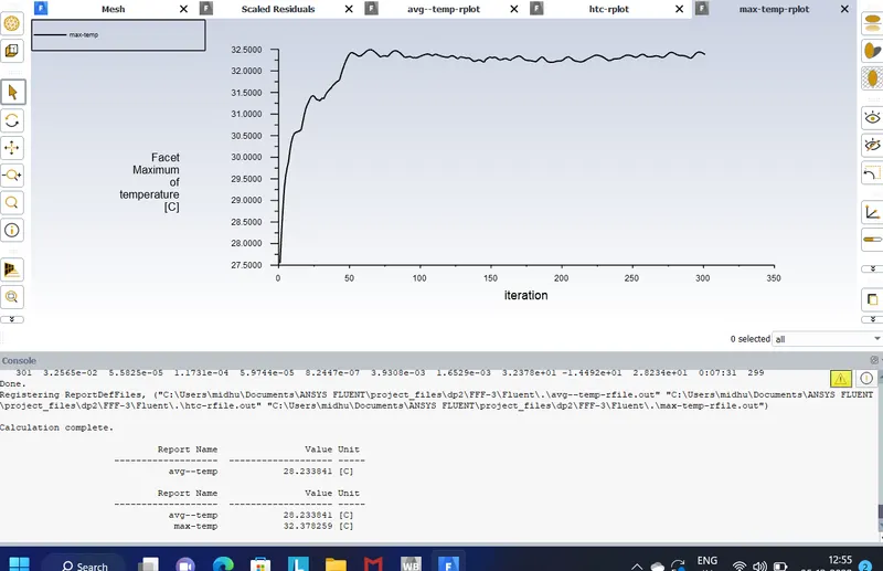
Maximum temeperature plot
Maximum temperature = 305.378K
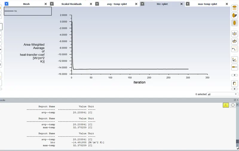
HTC plot
HTC = 14.491W/m2K
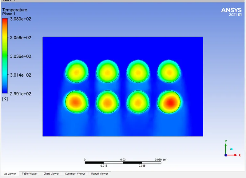
Temperature contour
From this it is clear that heat transfer efficiecy increased in this case beacuse from the more no of cells heat is transferring very quickly and almost uniform heat transfer is happening now.
Eventhough there is no much difference in the vlues of HTC, Average temperature and maximum temperature here heat is tranferring more uniformly than previous case
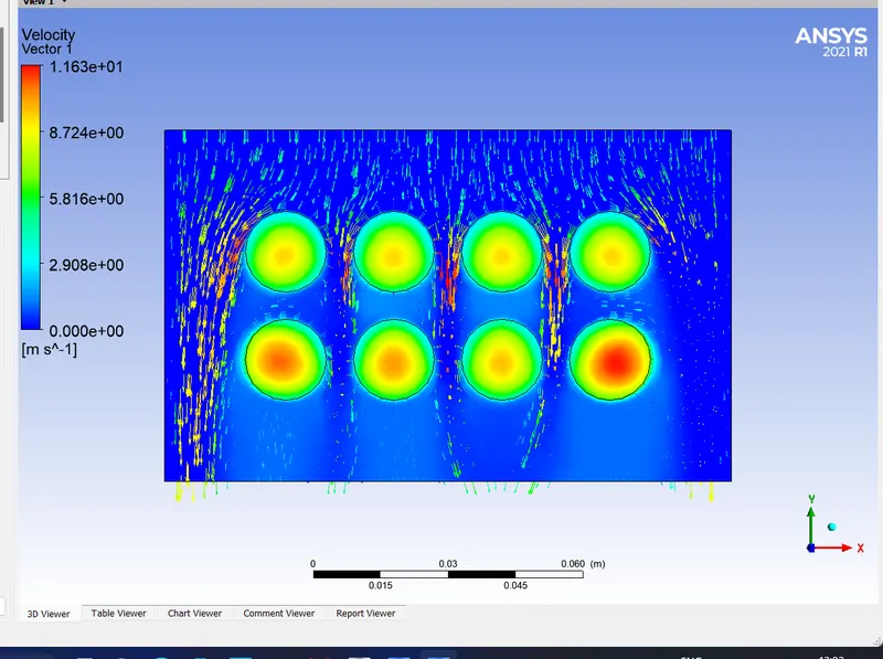
Velocity vector
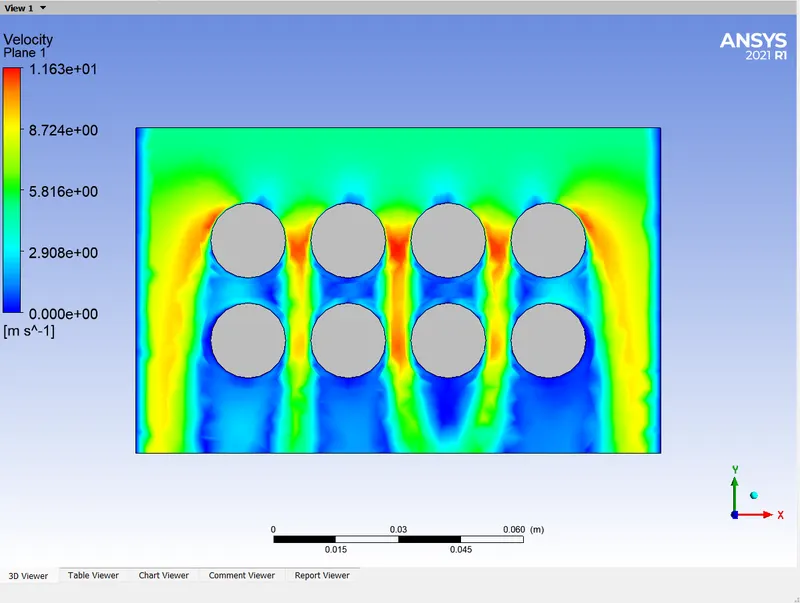
Velocity contour
RESULTS AND DISCUSSION:
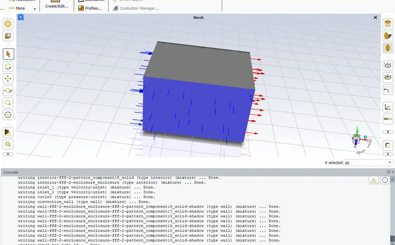
Giving two inlets and one outlet
RESULTS AND DISCUSSIONS:
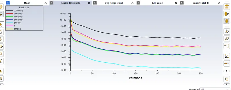
Residuals
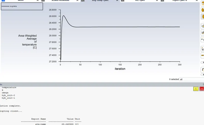
Average temperature plot
Average temeperature = 301.268 K
There is no much difference in the average temperature comparing to previous case
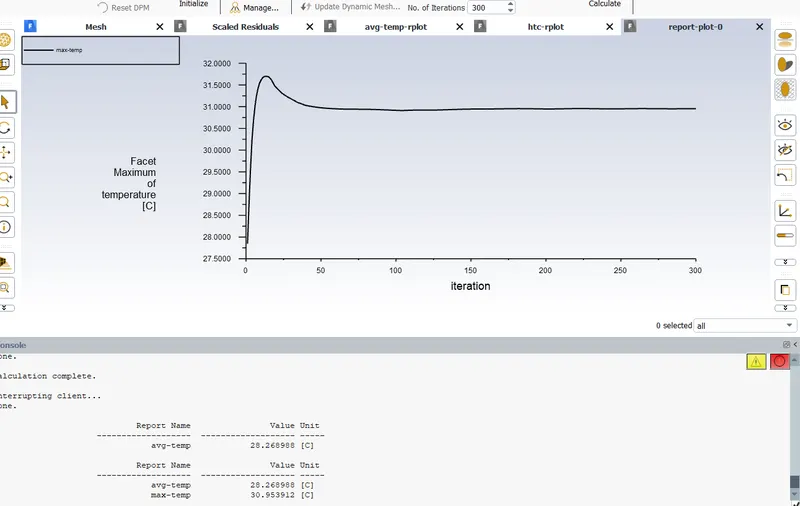
Maximum temperature plot
Maximum temeperature = 303.953K
Here maximum temperature is decreased comparing to previous case
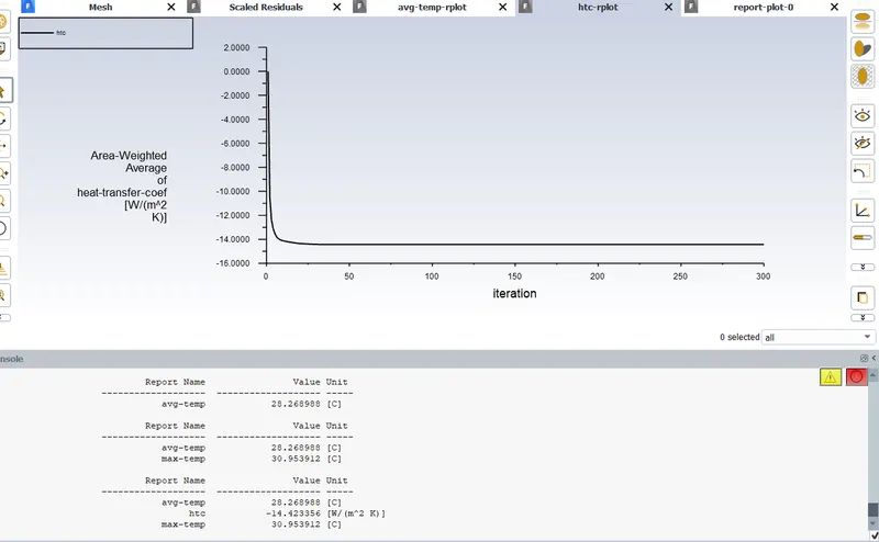
HTC Plot
HTC = -14.423W/m2K
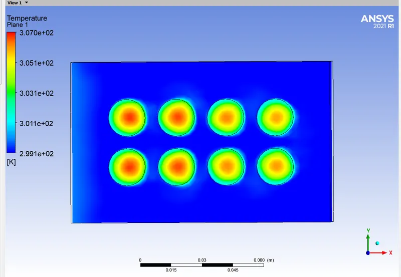
Temperature contour
Here heat transfer become more uniform and more uniform cooling is happening
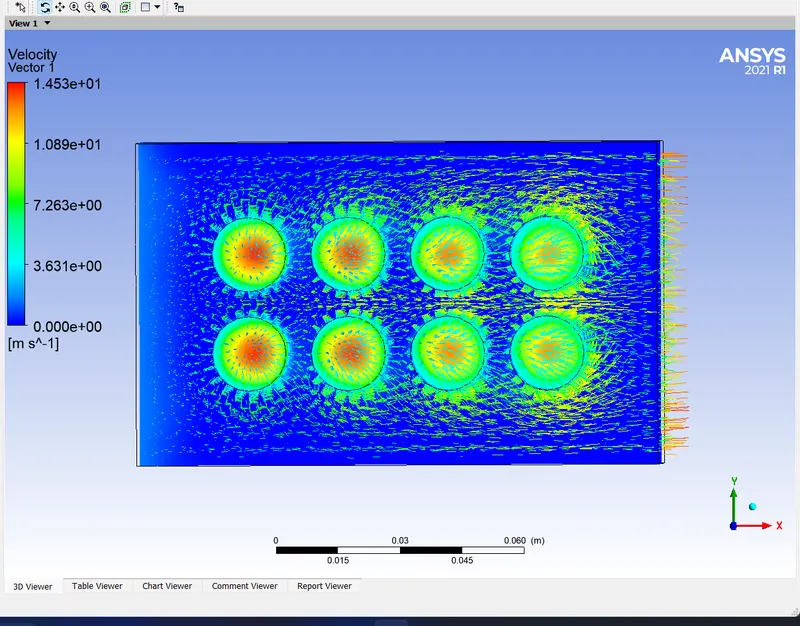
Velocity vector
NOTE: Video for this case uploaded below
Case 6: 2 Inlets, 2 Outlets, 6mm gap, 5m/s
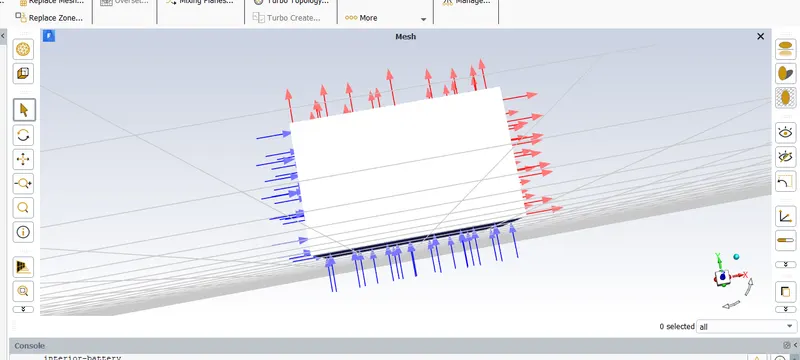
Given 2 inlets and 2 outlets
RESULTS AND DISCUSSIONS:
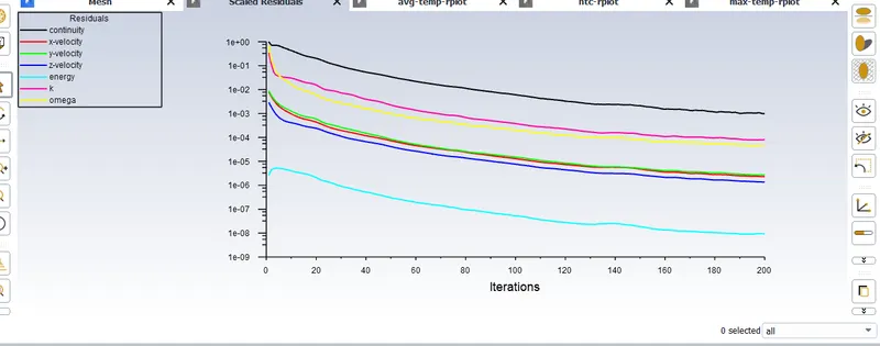
Residuals
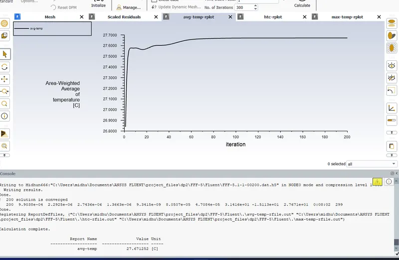
Average temperature plot
Average temperature = 300.671 K
Average temperature is less comparing to previous cases.
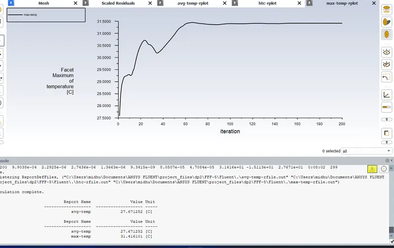
Maximum temperature plot
maximum temperature = 304.41 K
There is no much difference in maximum temperature comparing to previous cases.
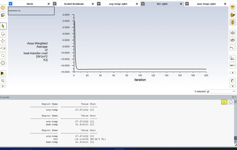
HTC Plot
HTC = -15.131 W/m2K
HTC increased comparing to previous cases.
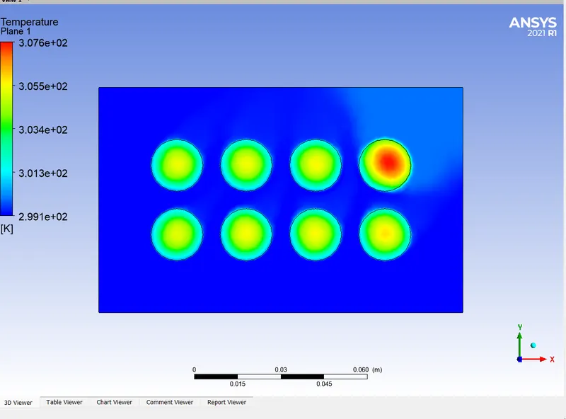
Temperature contour
Here we can see that cooling is more uniform and more heat transfer. Almost all cells are cooled very well but only at one cell which at the right top corner cooling is not proper and this is beacuse the air flow is not passing around that cell .
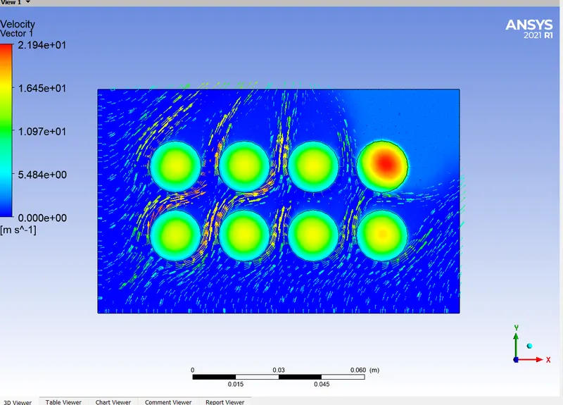
Velocity vector
It is clear from above figure that flow path of air is coming near to almost all the cells except the cell which is at the right top corner.
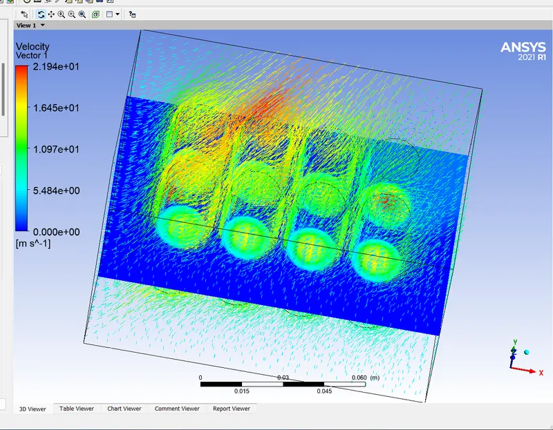
Velocity vector in whole fluid domain
Note: Video for this case uploaded below
CONCLUSIONS:
(1) Done mesh independance study and fixed mesh size as 5mm
(2) As the velocity of increases the value of convective heat transfer cofficient also increases and as a result the value of maximum temperature decreases.
(3) There is no much difference in the average temperature values as the velocity of air increases.
(4) When the gap between the cells increases, the value of convective heat transfer cofficient also increases and as a result the value of maximum temperature decreases.There is no much difference in the average temperature values as the gap between cell increases. But more uniform cooling happened when the gap between cells increases.
(5) Most effective cooling happened when 2 inlets and 2 outlets given.Here the value of heat transfer coefficient also high and as a result maximum temperature value decreases comapring to previous cases.