Week 10 - Simulating Combustion of Natural Gas.
Aim: - To perform heat transfer and battery cooling analysis of cylindrical lithium-ion batteries with heat generation condition.
Objectives: -
- Run the simulation by varying the velocity of air as 3, 5 and 10m/sec and discuss the results.
- Based on the results and on your judgment, select one case (3, 5 or 10 m/s) and vary the space between the batteries as 2, 4 and 6 mm, then discuss the results.
- Find out the maximum temperature and heat transfer coefficient obtained by the battery.
- Summarize the results in tabulation/ graphical form.
- Identify potential hotspots on the model
Theory: -
Battery
Battery is a device that converts chemical energy into electrical energy by means of electrochemical reaction. This reaction involves transfer of electrons from one material to another through electric circuit.
There are various types of batteries available which have different materials and generate different amounts of energy based on their properties, and based on their properties, efficiency and energy capacity, they are used for different applications, and among them Lithium-ion is most common.
When electrochemical reaction happens inside battery during charging or discharging, it generates electricity as well as heat, the temperature variation inside the batteries can lead to uneven temperature distribution which creates uneven charge/discharge behaviour within the pack.
And, high temperature in battery can evaporate battery vital liquids and weakens its charge also enhances rate of corrosion and it can damage the structure of battery. And due to high battery temperature, it catches fire.
Thermal runaway
In battery, thermal runaway is a phenomena or problem where there is sudden increase in temperature. In thermal runaway, the battery cell temperature rises incredibly fast (milliseconds). The energy stored in that battery is released very suddenly. And causes overcharging the battery, overheating the battery or exposing it to high temperatures, an excessively high discharge rate, a short circuit or damage such as a puncture.
Due to excess heat release during charging or discharging cooling of battery is necessary.
As current trend world is adopting zero emission, so people are switching from fossil fuel to renewable energy so there is sudden increase in demand of electric vehicles and with that there should be proper management of heat inside the battery for better efficiency as well as for safety of people.
So, battery needs a thermal management system.
Battery thermal management system: -
The Battery Thermal Management System (BTMS) is the device responsible for managing/dissipating the heat generated during the electrochemical processes occurring in cells, allowing the battery to operate safely and efficiently.
Especially in electric vehicles, it is a crucial factor for safety of vehicle and people.
Given below the classification of BTMS: -
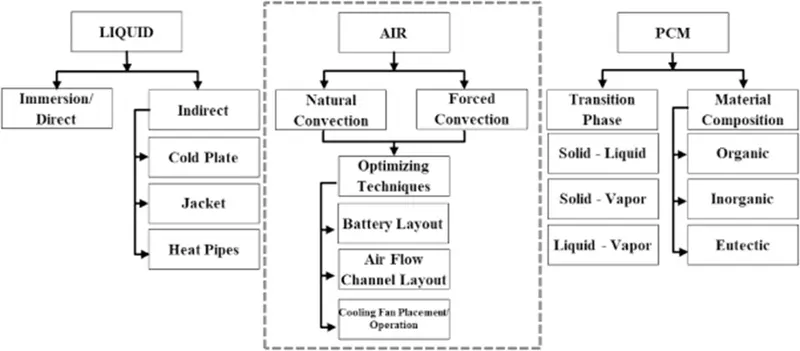
Different techniques for cooling the battery are:-
- BTMS
Active cooling
Active cooling is a heat-reducing mechanism that is typically implemented in electronic devices and indoor buildings to ensure proper heat transfer and circulation from within. active cooling is entirely dependent on energy consumption in order to operate. It uses various mechanical systems that consume energy to dissipate heat.
Various applications of commercial active cooling systems include indoor air conditioners, computer fans, and heat pumps
Passive cooling
Passive cooling uses free, renewable sources of energy such as the sun and wind to provide cooling, ventilation and lighting needs for a household. This additionally removes the need to use mechanical cooling.
- Air cooling
Forced air convection
When cooling is done through air which is being forced by external source such as fan, pump, suction device etc.
Natural air convection
When cooling is done through air by natural means , there is absence of external source to air flow.
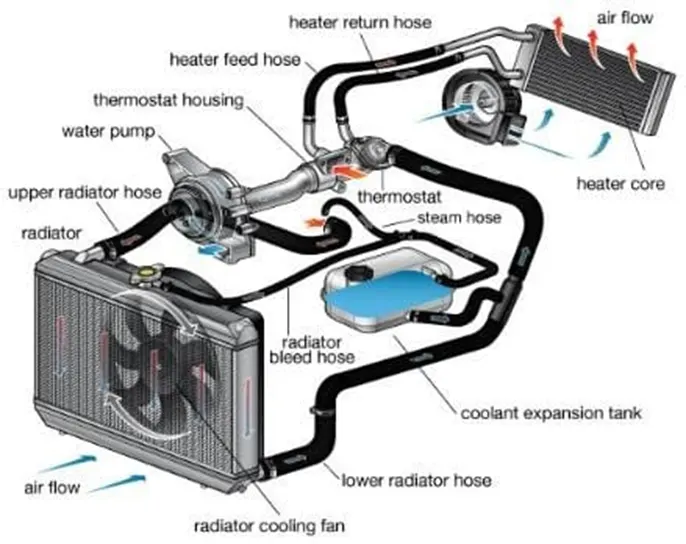
- Liquid cooling
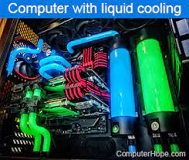
Liquid cooling refers to cooling by means of the convection or circulation of a liquid.It is most commercialized technique for battery cooling and can be used directly and indirectly in contact with the coolant and battery surface.
Examples of liquid cooling technologies include:
- Cooling by convection or circulation of coolant, including water cooling
- Liquid cooling and ventilation garments, worn by astronauts
- Liquid metal cooled reactors
- Radiators (engine cooling)
- Cooling towers
- Liquid jacket cooling
- Liquid plate cooling
- Phase change phenomena cooling
Phase-change cooling involves harnessing a cooling fluid's natural latent heat of vaporization, or the point at which it transitions from a liquid phase into a gaseous phase.
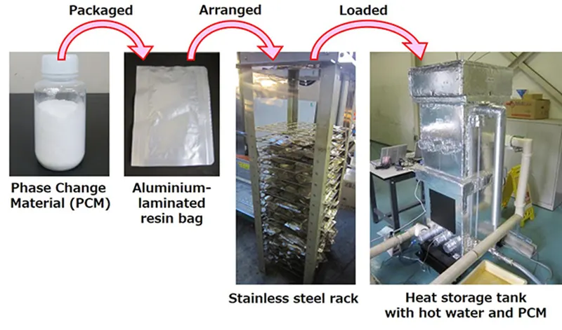
Phase change material
A phase change material (PCM) is a substance which releases/absorbs sufficient energy at phase transition to provide useful heat or cooling. Generally, the transition will be from one of the first two fundamental states of matter - solid and liquid - to the other.
Classification of Phase change material
- Organic
- Inorganic
- Hygroscopic
- Soli-solid PCM
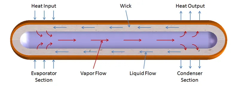
Heat pipes
Heat Pipes are one of the most efficient ways to move heat, or thermal energy, from one point to another. These two-phase systems are typically used to cool areas or materials, even in outer space.
The pipe uses a combination of evaporation and condensation of this working fluid to transfer heat in an extremely efficient way.
Procedure: -
- Pre-processing
Geometry
- Open space claim in workbench
- Create circle of diameter 18mm and convert it into surface and extrude it upto 65mm and create a battery. So, the volume of battery is 1.65´10-5
- Now in design, go to linear pattern and make an array of 2´4 of battery assembly and distance between batteries will vary based on different cases which is given below.
- Create an enclosure of dimension
|
faces |
Dimension in mm |
|
Top |
15 |
|
Bottom |
15 |
|
Front |
20 |
|
Rear |
20 |
|
Sides |
20 |
5. Now do share topology by clicking on share option in workbench tab option
Meshing
- Go to Ansys mesh
- Give inflation of 10 layers at growth rate of 1.1 with first layer thickness 0.3mm
- Now give element size 3mm and generate mesh also create 4mm and 5mm element size mesh for mesh independence study
- Give name selection to each surface or body as inlet, outlet, Convection wall, battery and update the mesh
- Solving
Solver
- Open ansys fluent solver
- As the flow is incompressible so select pressure based solver
- And this is a steady state simulation so select steady state condition
- In physics , enable energy, as here temperature is included , interaction of heat is taking place
- In turbulence model, select k-omega standard turbulence model
- Go to material, create lithium material by copy aluminium and renaming it and give lithium properties as
|
Density |
2700 kg/m3 |
|
Specific heat |
900 J/kg.K |
|
Thermal conductivity |
7.14 w/m.K |
7. As the battery is lithium ion so here lithium material is created for battery, Aluminium for enclosure, Air is fluid material because here cooling takes place via air.
8. In cell zone condition, assign proper material to different domains like
Battery- solid(Lithium) , and enable source terms, as source is only one and that is battery.
Given heat generation per battery is 10W so energy source is 604595 W/m3
Convection wall- solid(Aluminium),
Fluid domain- fluid(air)
9. Now give boundary condition,
Inlet- 3m/s , 5m/s , 10m/s
Outlet – pressure-outlet
Convection wall –
- Thermal condition – Convection
- Heat transfer coefficient -5 w/(m2K)
- 10. Create report definition for average temperature for battery and heat transfer coefficient.
- 11. Now initialize the problem and do autosave for each iteration for animation of simulation
- 12. Compute the problem for 500 iteration.
- 13. By giving different battery space and different velocity we have 5 cases to solve
|
Cases |
Velocity |
Battery space |
|
Case 1 |
3m/s |
4mm |
|
Case 2 |
10m/s |
4mm |
|
Case 3 |
5m/s |
4mm |
|
Case 4 |
5m/s |
2mm |
|
Case 5 |
5m/s |
6mm |
- Postprocessing
- Open CFD-Post.
- Create a plane.
- Create velocity, temperature contour and velocity vector for all the cases.
- And create an animation.
Result: -
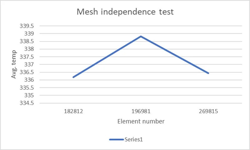
- First mesh independence study was done to check the variation of result with change in element number and verify which mesh is best suitable.
Here, Mesh independence study was done at battery space 2mm, velocity 5m/s and variation in element size was from 3mm to 5mm which is tabulated below with graph. And from observation, it was decided that element size of 3mm will be used for all the cases.
Mesh independence study
|
Element size (mm) |
Element number |
Avg. temp |
|
3 |
269815 |
336.44 |
|
4 |
196981 |
338.83 |
|
5 |
182812 |
336.18 |
- Given below is the table of all the cases result where for 1st three cases air flow velocity is changing but battery space kept constant at 4mm and for remaining 2 cases air flow velocity kept constant but battery space vary , so here simulation was done at battery space 2mm, 4mm and 6mm also at velocity 3m/s,5m/s and 10m/s.And variation in Avg. temp of battery and heat transfer coefficient with change in given parmeter is observed.
|
Cases |
Velocity |
Battery space |
Avg. temp (K) |
Heat transfer coefficient(w/m2K) |
|
Case 1 |
3m/s |
4mm |
347.123 |
-41.377 |
|
Case 2 |
10m/s |
4mm |
321.667 |
-72.675 |
|
Case 3 |
5m/s |
4mm |
333.842 |
-53.660 |
|
Case 4 |
5m/s |
2mm |
336.448 |
-50.986 |
|
Case 5 |
5m/s |
6mm |
331.619 |
-56.006 |
All the contours plot are given in the document attached below.
google drive link :-
https://drive.google.com/drive/folders/1Ke_RlPXWCJsB2IBHe2zb28YkesuKXXkI?usp=sharing