Week 10 - Simulating Combustion of Natural Gas.
AIM:- Perfom analysis on Cylindrical Lithium Battery of 4 X 2 create Enclosure and find Average temperature with Heat transfer coefficient for different velocities(3,5,10 m/s) , Space between batteries (2,4,6mm) and mesh independent study for Any one case and provide Visual hotspot results.
THEORY
As we know Electronic vehicle has Battery as main source of power and also in Hybrid vehicles the Battery source power is used to increase efficiency of vehicle By using battery source for many process like deaccelerating, regenerative braking , More torque input etc. But recently the Battery overheating has been main concern for different types of electric vehicle motor 2 wheeler or 4 wheeler. To ensure proper output without any risk following conditions must be kept for efficient performance.
- To Ensure battery operating condition temperature range between 15 C to 35 C.
- Monitior state of battery and detect te critical point of batteries failures and deliver alarm messages.
- Supress thermal Runaway propagation.
For above mentioned purpose the BTMS system is introduced
BTMS(Battery thermal managment system)
This system provide essential information such as Thermal protection, Over voltage protection, Prolong Battery life, cell balancing,Soc, SoH calculation etc.
The high battery temperature leads to poor performances ,Shorten battery life and also has risk of exploding.The main purpose of BTMS is to keep optimum temperature and keep informations for temperature variations caused in battery modules.
The rising temperature cannot be diminished even by optimum usage because there will always be loss of electrical energy in form of heat but to ensure optimum operating conditions Cooling Methods are used in BTMS.
Those methods are
- Air Cooling
Air is most convinient in term of source as it can provide by surround and other mediums.Which is why it is most commonly used .But it is not an effective coolant because of its lower heat capacity and low thermal condutivity.Its only conviniet in means of low maintenance of cost.
The air cooling is possible wither by forced convection mode and natural convection mode. Natural convection cooling is suitable only for low-density batteries,and typical blowers can be used to enhance convection heat transfer rate.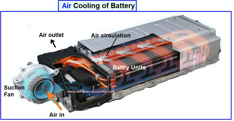
When air is used for cooling of battery modules arranged in series,The middleand rear portion of batteries are at high temperature to the low heat capacity of air.the tempretaure of battery pack near outlet is very high and temperature distributions is highly non-uniform,to cool effectively,we need to increase the flow rate and turbulence of airflow. - Liquid Cooling
Liquid cooling have high convective heat removal rate due to higher density and heat capacity than air. Liquid cooling can also reduce noise level.However the complexity of the liquid cooling sytems leakage potential can be defined into direct and indirect cooling.
In direct method th fluid is directly used as medium as we can see we use more electical medium so direct method may be appropriate in cases like gear lubrication etc. but Only convinient method in case of electronical device are indirect method of cooling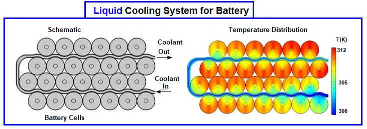
As we can see in indirect cooling the liquid is carried in pipe .The fluid has inlet to outlet flow and path is created between batteries so all heat absorbtion can be done by liquid in process and temperature is managed.
In some cases they also add cool plates between batteries .Plates inner portion may have liquid movement of need to be changed in amount of time . - PCM(Phase Change material)
The phase change material absorbs heat significantlt due to high latent heat during battery discharge.the PCM have been used for thermal management have a melting point in optimum performing range of Lithium cells.The temperature needs to remain for a long time.PCM as parafifn has a melting point of range of 32-38 C which is mixed with graphite flakes to imporve thermal conductivity.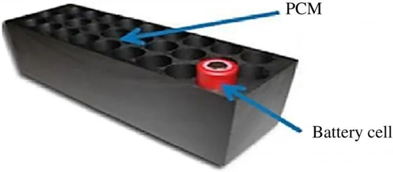
The graphite flakes wll also create semi matrix block which will contain the paraffin particles.When paraffin melts,It stays within this matrix and whole composition remains in solid form.The advantage of PCM is that they also act as shields in case of thermal runaway.
Solving Method
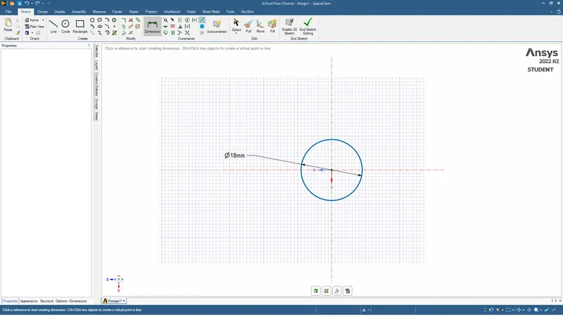
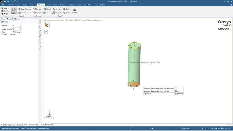
- First we will open space claim in geometry in ANSYS -FLUENT . where we will create cylindrical battery of size 18mm diameter and length 65mm.
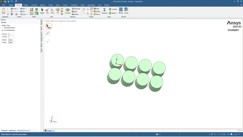
- Then we will use pattern to create battery for 4X2 size with using pitch as setting distance between batteries 2,4,6 mm as asked.
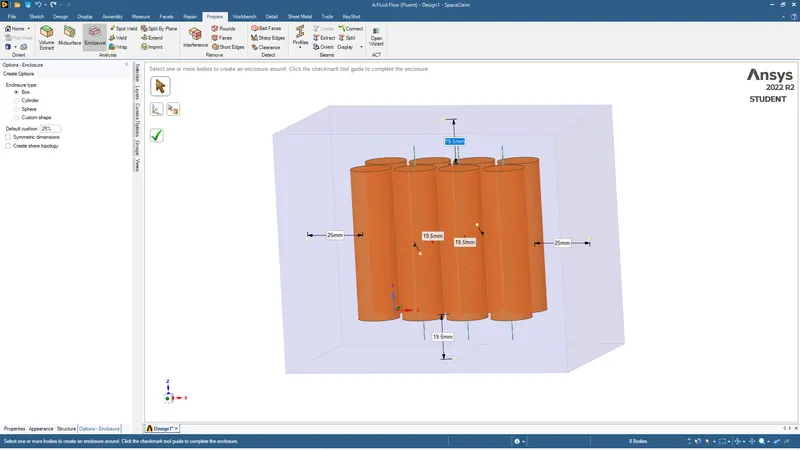
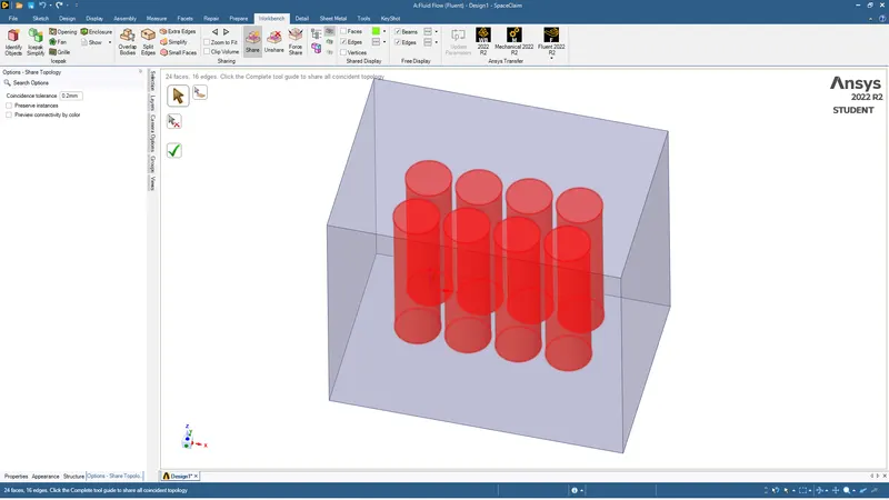
- Then we will create enclosure and use share to share data in enclouse and open geometry in mesh.
- In mesh we will crete mesh for default coarse mesh and size of 2.5mm for fine mesh for mesh independent study.
- In both fine and coarse mesh case we will use inflation and add first layer of 0.4mm which is calculated by Y+ model value 5 in Y+ calculator.
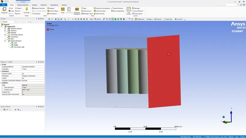
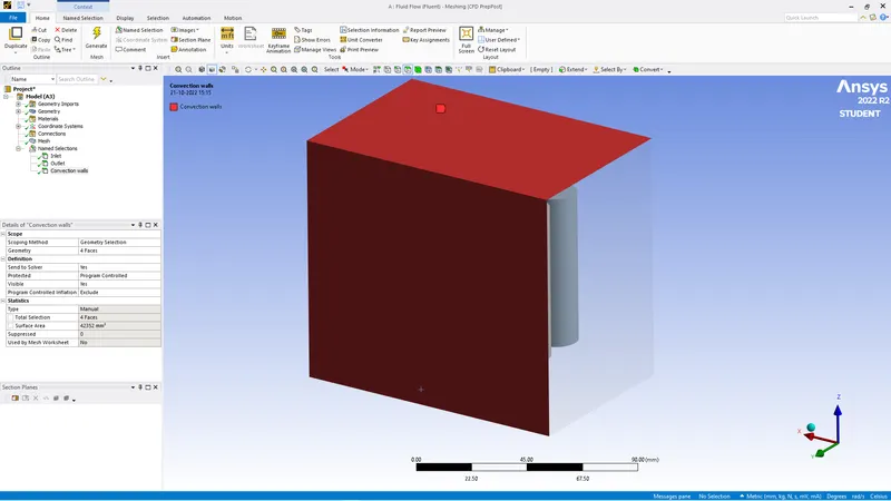
- We then give anme selction for inlet,outlet,batteries and convection walls.
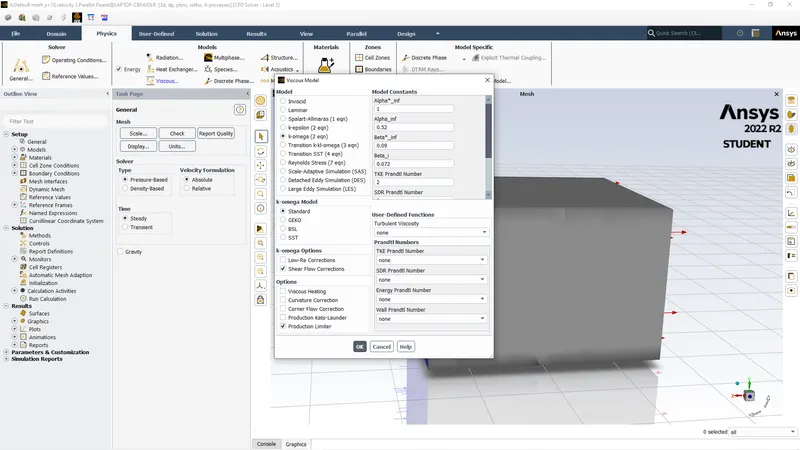
- We then open geometry in Solver where we use pressure based staedy mode, k-Omega(standard) model .
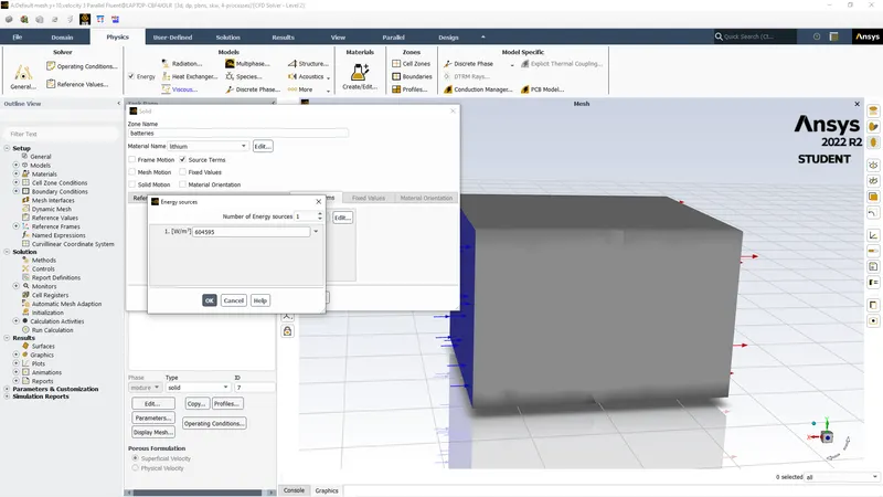
- We copy aluminium from data base in materials and add lithium user defined properties as mentioned . We thenopen cell zone and change all material to lithium user defined and generate heat source where we insert constant value calculated by divinding 10W by volume(1.654 X10^-5) which is eqials to 604595 W/m^3.
- Then we give velocity at inlet 3,5,10m/s according to case and initialize the model and run for 600 Iterations .
- We create contour for temerature and plots for Avgerage temperature at battery and heat transfer coefficient at battery and run the model.
PROCESS WITH DETAILING
Geometry
First we create cyndrical battery of dia 18mm and length 65mm in Space claim ANSYS FLUENT
Then we go to pattern in DESIGN tool and create 4 X 2 pattern with required pitch according to distance required if distance between batteries required is 2 mm then pitch wll be 20mm .If required 4mm then pitch will be 22mm & similarly 24 mm for 6mm distance.
After creating Pattern we will enclose this body By going to PREPARE tool and create ENCLOSURE click at symmetric view and provide length accordingly for enclosure.
After encloure we will share topoogy for exact details in the enclosure and just unclick the preserve iterations.
After finishing we go to Meshing .
Meshing
Here we will perform mesh independent study so we wil take 2 cases for meshing default mesh which we will consider coarse mesh and fine mesh which will be equal to 2.5 mm
First we create mesh
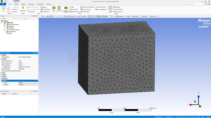
Then we will use insert and use inflations and use Y+ model for first layer thickness we will use y+ calculator and we will give viscosity and frontal length which will be diameter 0.018 m . and we will get first layer thickness of 0.4mm and layers 20. We will use this in inflation and give enclosure body as boundary and inner batteries as Walls.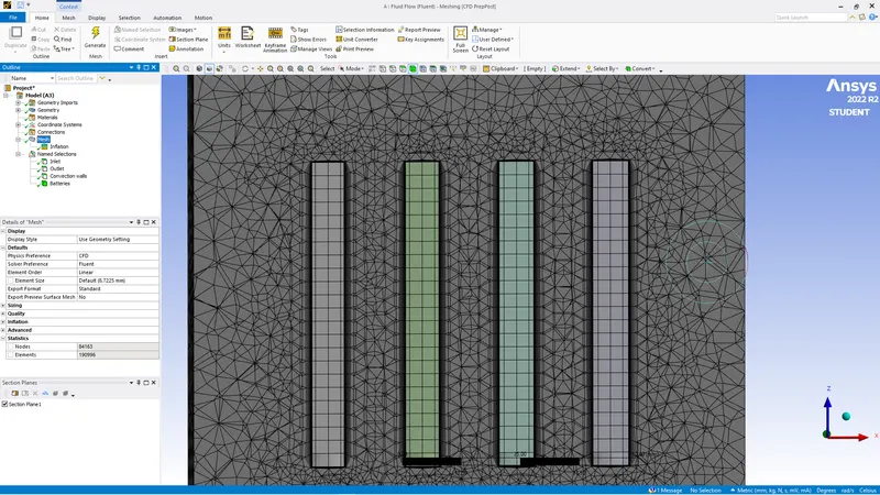
In same way we will create inflations but refine mesh length to 2.5mm in fine mesh case
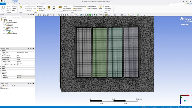
After inflation we will update mesh and give name sections
Inlet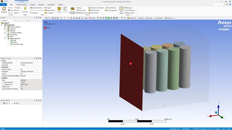
OUTLET
Convection walls
Batteries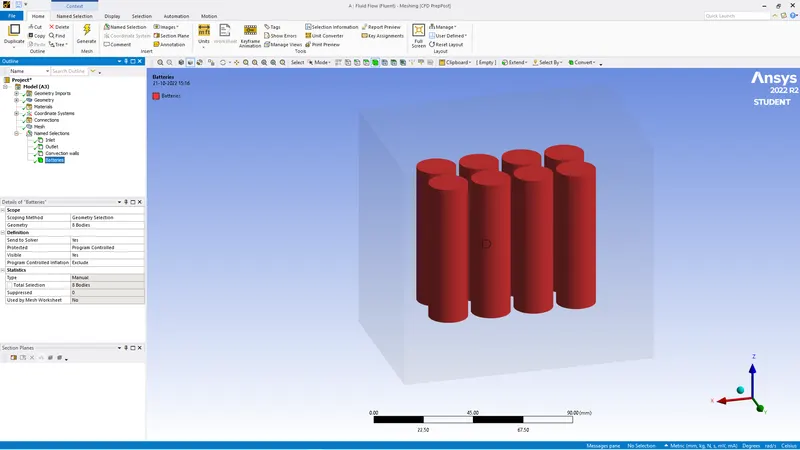
AFter this we will open solver
SOLVER
First we will give general settings pressure based model, Steady, K-omega(standard) settings
As the required material for battery is lithium we will create material by copying th material of alluminium and give its appropriate values.
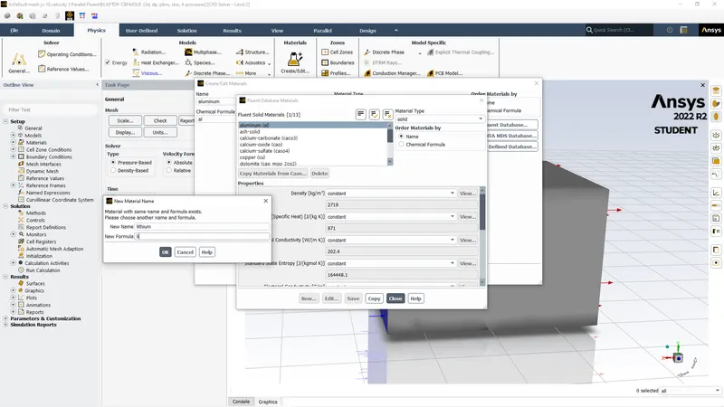
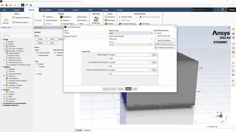
Lithium has density of 2700 kg/m^3, Specific heat of 900 J/kg k & Thermal conductivity of 7.14 W/mk.
after giving values we will change material in cell zone conditions
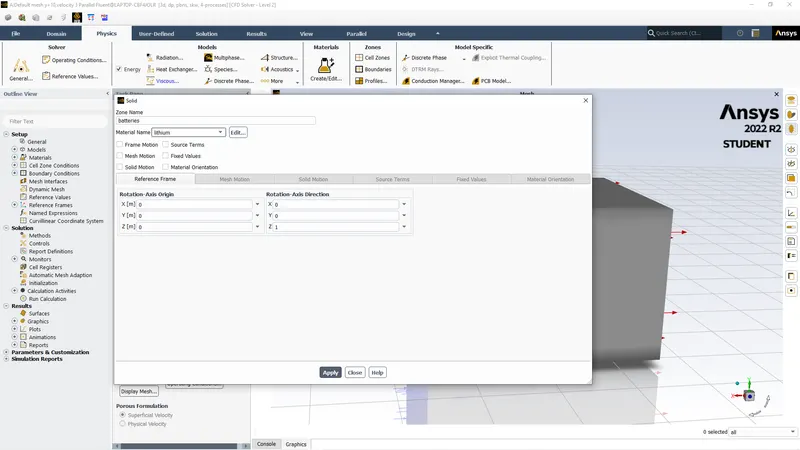
We will create energy source of heat which we can calculate by dividing energy by volume In this case the Energy is 10W and volume of dia 18mm & 65mm length cylinder is 1.65 X10^-5 m dividing we get 604595
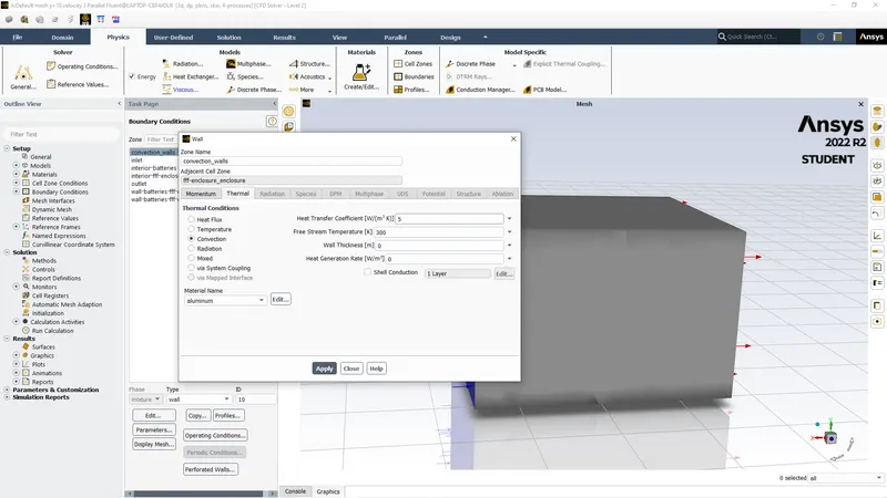
After this we will give convective wall conditions we change thermal condition to convection and give value of 5
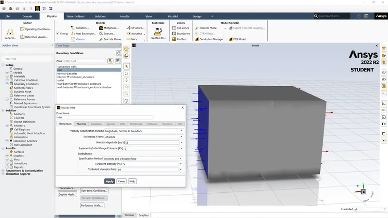
Then we give inlet boundary condition where we will give velocity of 3,5,10 m/s
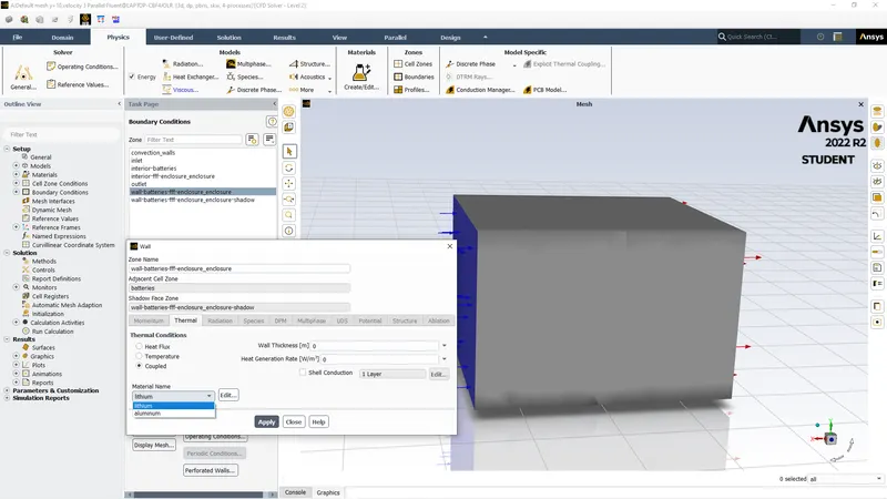
We will change battery walls material to lithium
Then we will create report of plot for temperature and Heat transfer coefficient. and initialize Then create contour for temperature and autosave for animation process and run for 600 iterations then 350 iteration.
RESULTS
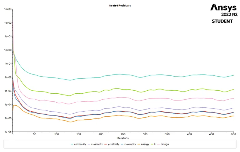
CASE 1 ( Coarse mesh and velocity 3m/s with space between the battery is 2mm)
RESIDUAL
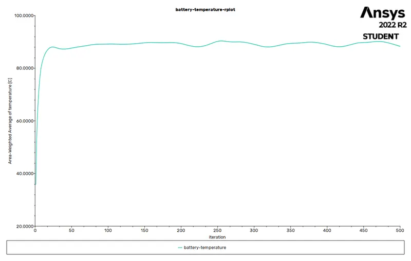
TEMPERATURE PLOT
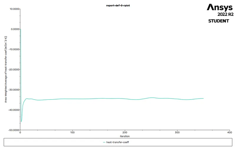
HEAT TRANSFER COEFFICIENT
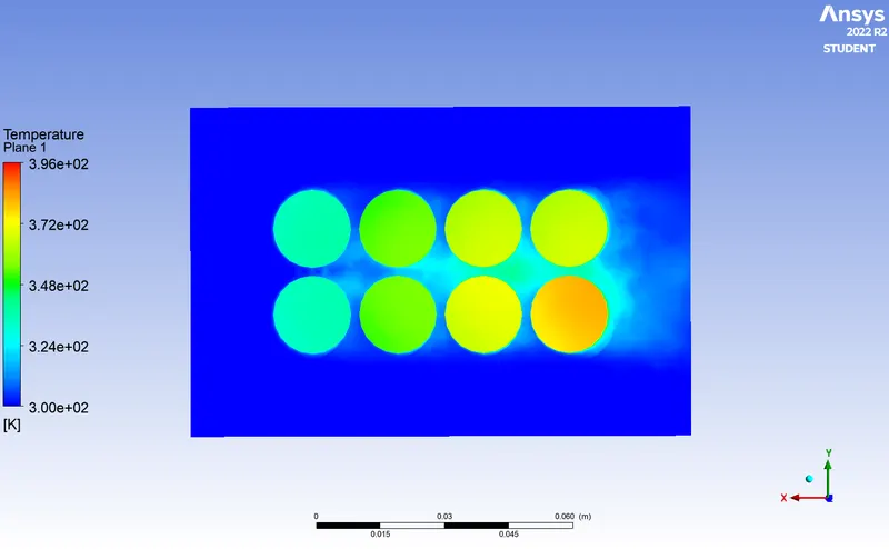
TEMPERATURE CONTOUR
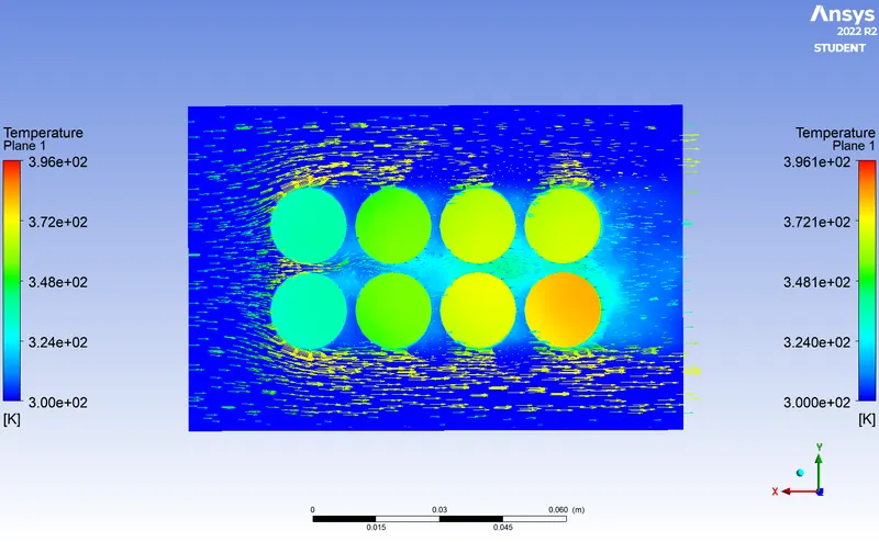
VELOCITY VECTOR
AVG. TEMPERATURE = 362.56 K
HEAT TRASNFER COEFF.= -34.38 W/m^3 k( -VE SIGN DENOTE THE LOSS OF HEAT FROM BATTERY DUE TO AIR FLOW )
CASE 2 (Fine mesh =2.5mm, Velocity of 3m/s & space between batteries is 2mm)
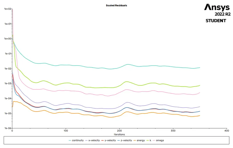
RESIDUAL
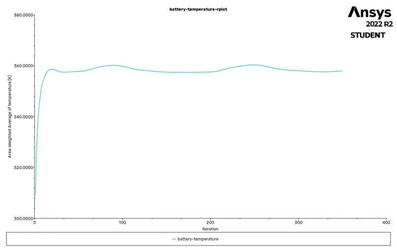
TEMPERATURE PLOT
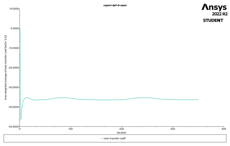
HEAT TRANSFER COEFFICIENT
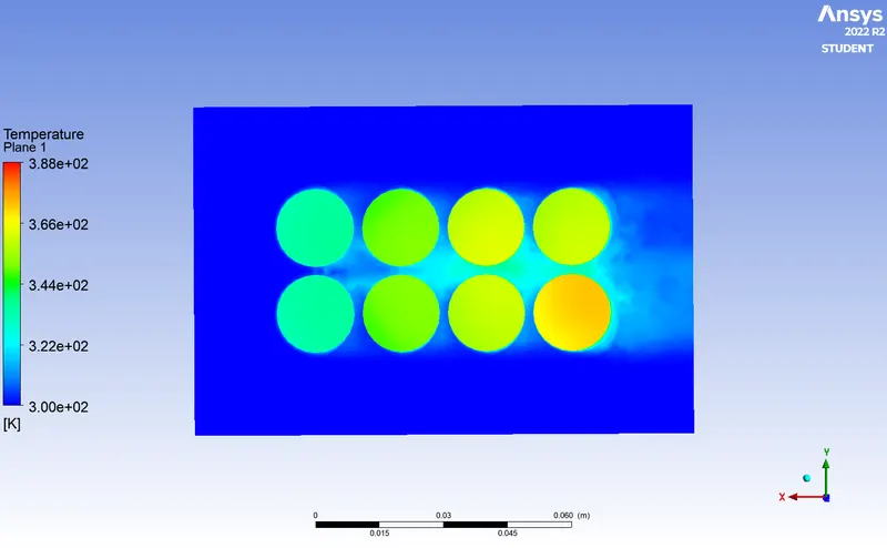
TEMPERATURE CONTOUR
VELOCITY VECTOR
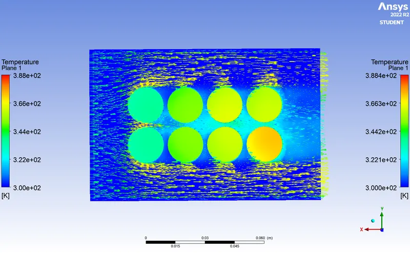
AVG. TEMPERATURE = 357.99 K
HEAT TRASNFER COEFF.= -36.26 W/m^3 k( -VE SIGN DENOTE THE LOSS OF HEAT FROM BATTERY DUE TO AIR FLOW )
CASE 3 (Mesh =2.5mm, Veocity 5m/s & spacing between batteries is 2mm)
RESIDUAL
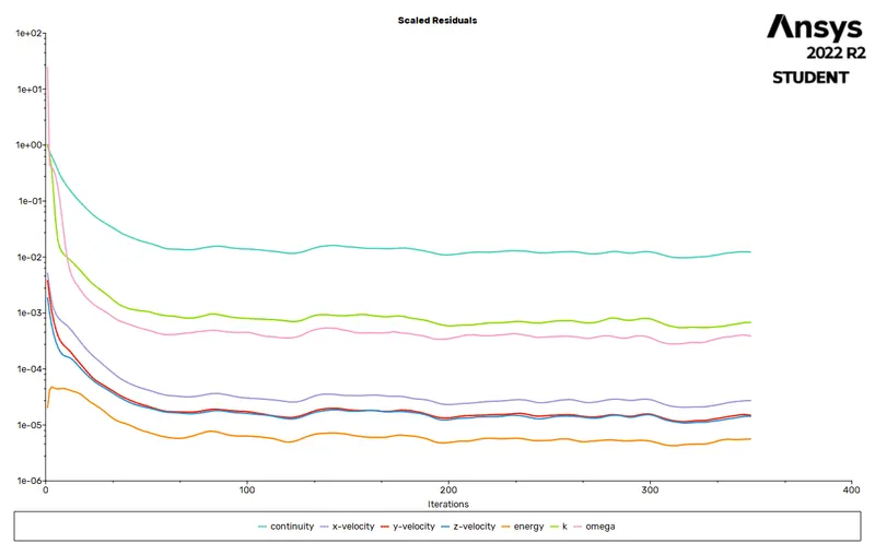
TEMPERATURE PLOT
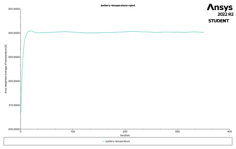
HEAT TRANSFER COEFFICIENT

TEMPERATURE CONTOUR
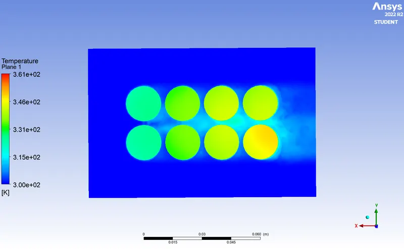
VELOCITY VECTOR
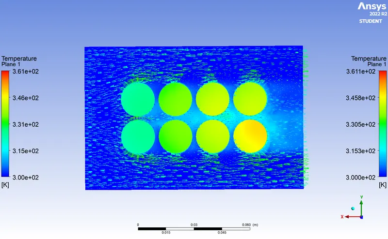
AVG. TEMPERATURE = 340.21 K
HEAT TRASNFER COEFF.= -48.14 W/m^3 k( -VE SIGN DENOTE THE LOSS OF HEAT FROM BATTERY DUE TO AIR FLOW )
CASE 4 (Mesh=2.5mm, velocity = 10m/s & spacing between batteries is 2mm)
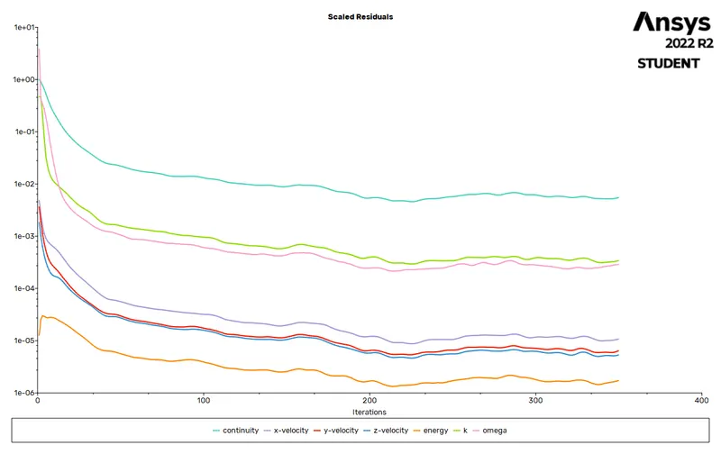
RESIDUAL
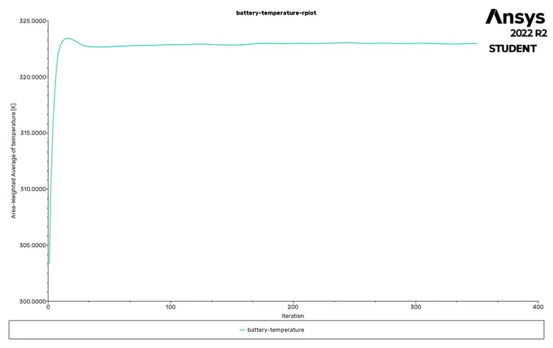
TEMPERATURE
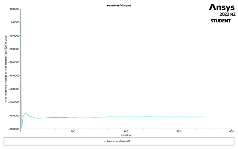
SURFACE HEAT TRANSFER COEFFICIENT
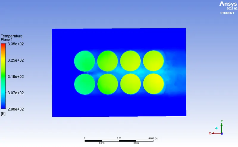
TEMPERATURE CONTOUR
VELOCITY VECTOR
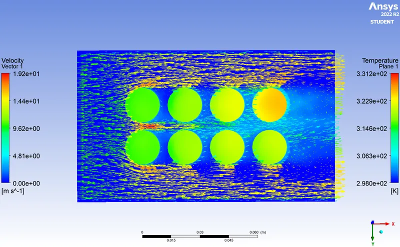
AVG. TEMPERATURE = 322.98 K
HEAT TRASNFER COEFF.= -70.98 W/m^3 k( -VE SIGN DENOTE THE LOSS OF HEAT FROM BATTERY DUE TO AIR FLOW )
CASE 5 ( Mesh=2.5mm, Velocity =10m/s & spacing between batteries is 4mm)
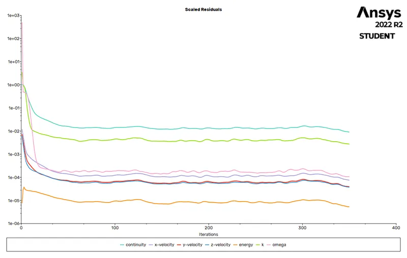
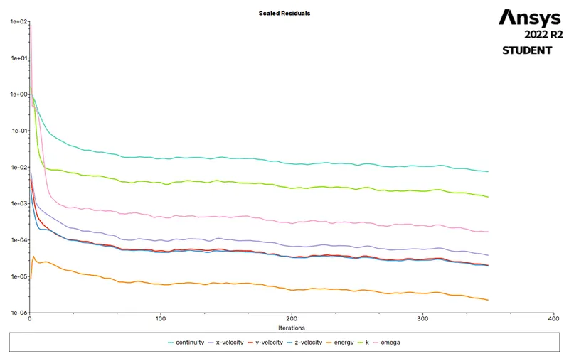
RESIDUAL
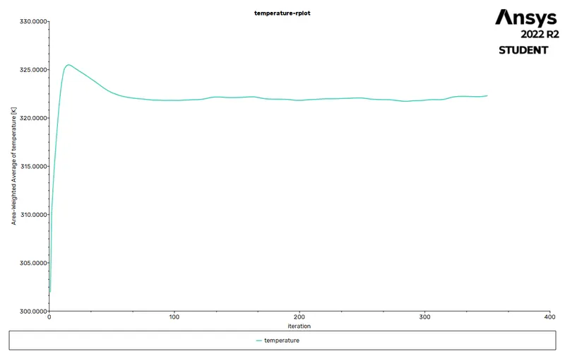
TEMPERATURE PLOT
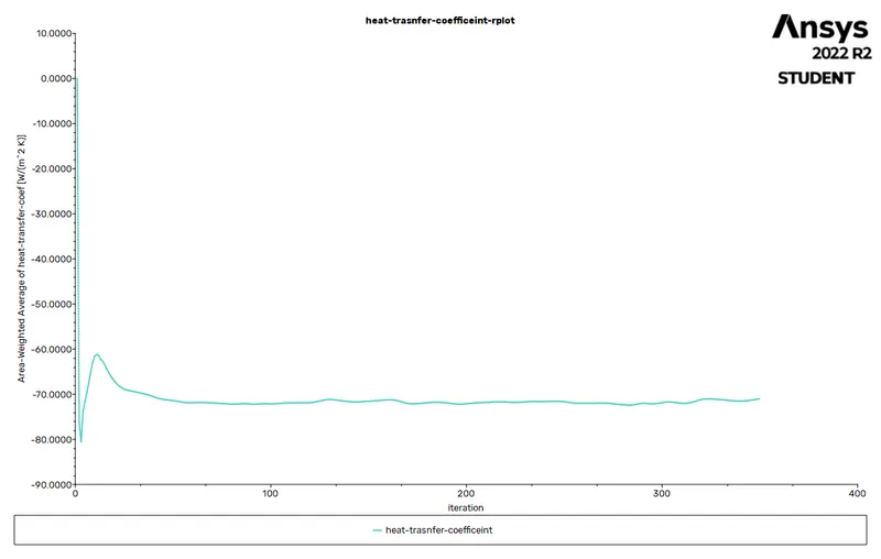
HEAT TRANSFER COEFFICIENT
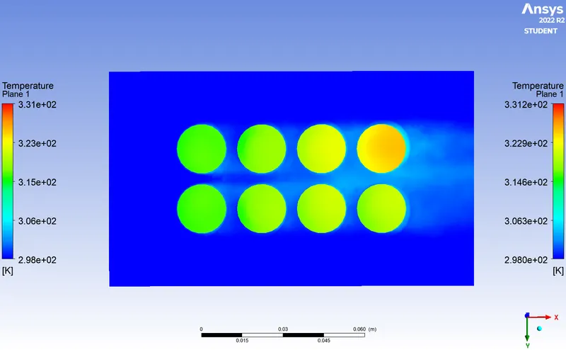
TEMPERATURE CONTOUR
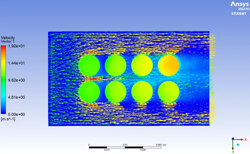
VELOCITY VECTOR
AVG. TEMPERATURE = 322.29K
HEAT TRASNFER COEFF.= -71.02 W/m^3 k( -VE SIGN DENOTE THE LOSS OF HEAT FROM BATTERY DUE TO AIR FLOW )
CASE 6 (Mesh =2.5mm, Velocity =6m/s & distance between batteries is 6mm)
RESIDUAL
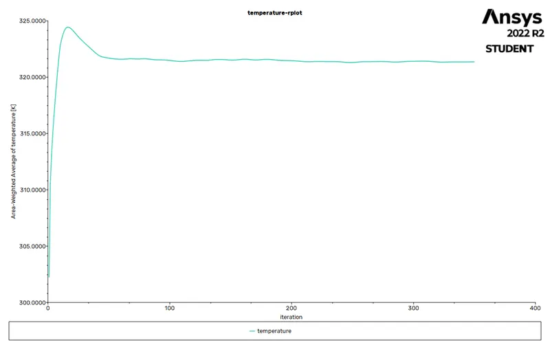
TEMPERATURE PLOT
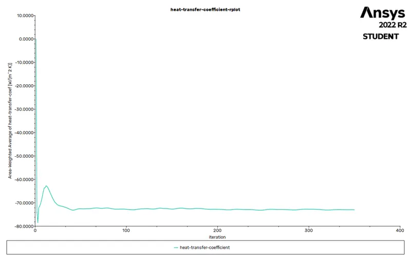
HEAT TRANSFER COEFFICIENT
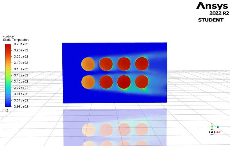
TEMPERATURE CONTOUR
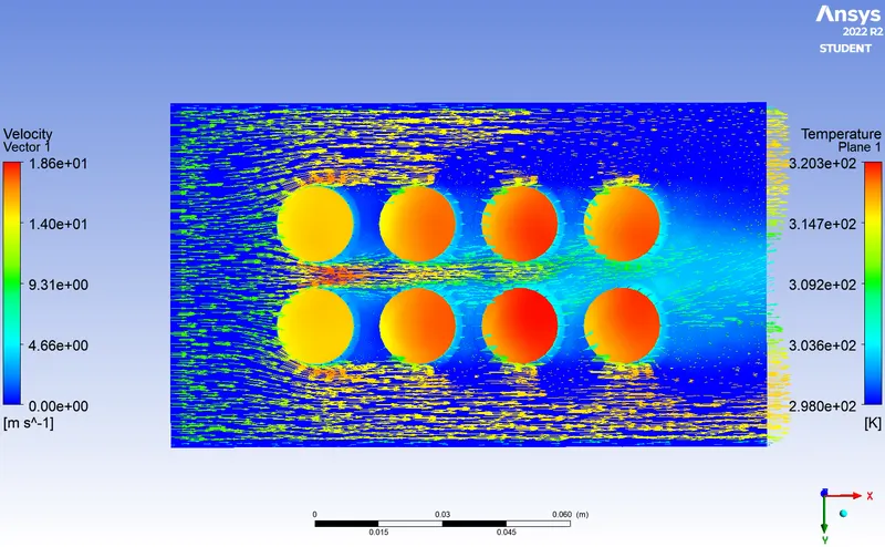
VELOCITY VECTOR
AVG. TEMPERATURE = 321.25 K
HEAT TRASNFER COEFF.= -72.9 W/m^3 k( -VE SIGN DENOTE THE LOSS OF HEAT FROM BATTERY DUE TO AIR FLOW )
CONCLUSION
| CASES | MESH SIZE | DISTANCE BETWEEN BATTERIES | AVERAGE TEMPERATURE(k) |
HEAT TRANSFER COEFFICIENT |
| 1 | 9MM APPROX | 2MM | 362.5 | -34.38 |
| 2 | 2.5MM | 2MM | 357.99 | -36.26 |
| 3 | 2.5MM | 2MM | 340.21 | -48.14 |
| 4 | 2.5MM | 2MM | 322.98 | -70.98 |
| 5 | 2.5MM | 4MM | 322.29 | -71.02 |
| 6 | 2.5MM | 6MM | 321.25 | -72.9 |
- In mesh independent study we can clearly see the temperature for same velocity 3m/s with distance 2mm between batteries varies by 5K this is due to fine mesh has fine elements which even though will take more computational time but will give you appropriate result.
- In varying velocity case we may see the temperature decreasing with higher velocity which is intact the exact solution as in real situation higher velocity means heat transfer rate will be higher and batteries will get coler much faster.
- By varying the space between batteries we can see the result doesn't differ in drastic way only fraction of change can be seen. Which is appropriate because the air flow circulation will not become balnaced by just increasing few milimeters of distance .
- we can conclude with this that if we use air cooling method we may reduce the spacing size to optimum for reduction of Size of battery its more efficient if we increse velocity of Air flow in cooling process .This method can also be seen in laptops when cooling fan runs in smaller micro chops the velocity of air needed is higher that causes high sound in gaming laptops which require high performance.
LINK FOR ANIMATION:-https://drive.google.com/file/d/1qalF_O2CWQVJwdhZDjpiMqA5OugrS1fG/view?usp=sharing