Week 10 - Simulating Combustion of Natural Gas.
AIM:
In this challenge simulating combustion of the natural gas is should be carried out in the detailed manner and that is carried out in the two parts;
Part I
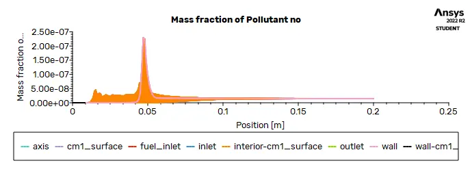
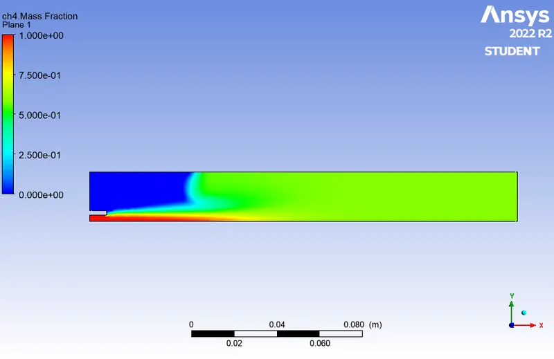
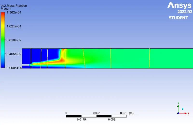
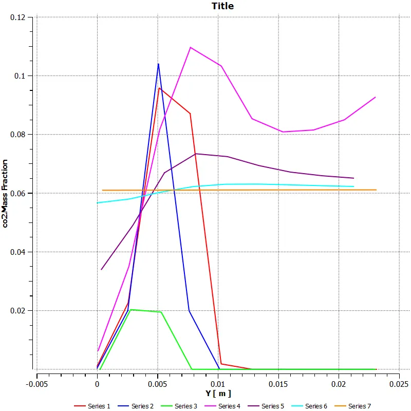
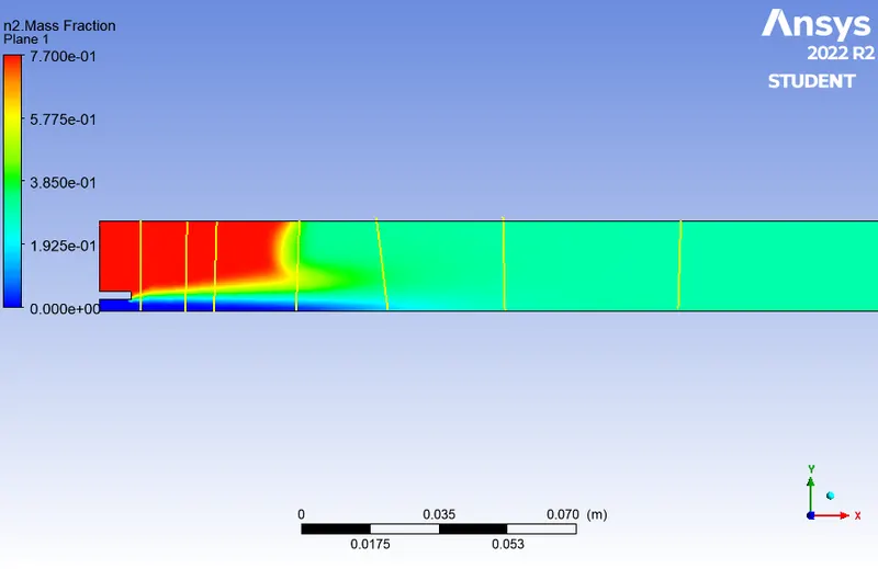
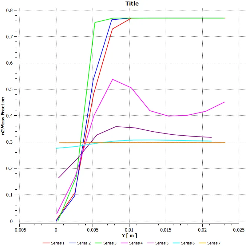
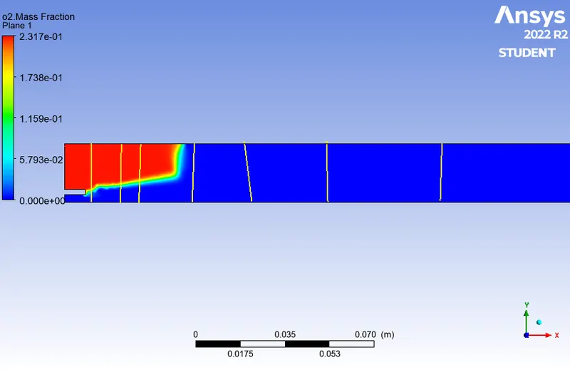
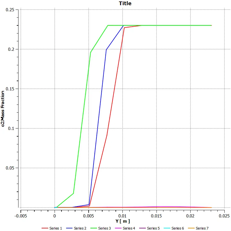
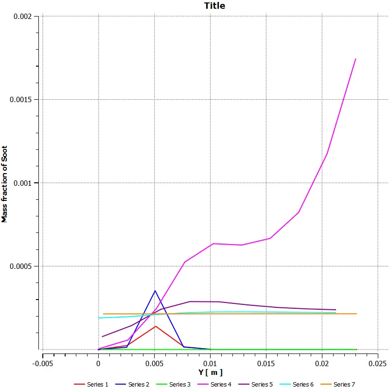
Perform a combustion simulation on the combustor model and plot the variation of the mass fraction of the different species’ in the simulation using line probes at different locations of the combustor as shown in Fig. You need to plot for CO2, H2O, CH4, N2, O2, NOx emissions & Soot formation.
Part II
As you must have observed from the above simulation, the Nox and soot is getting formed at the outlet of the combustor. Such formation has harmful effects on the environment and humans. The stringent government norms also demand the least formation of Nox and soot and to satisfy those requirements, you need to check the effect of adding the water in the fuel.
In this part, you need to add the water content in the fuel from 5% to 30% by mole and observe the effect of it on the results. It is necessary to provide line plots and contours to prove your claim.
INTRODUCTION:
NATURAL GAS:
Natural gas is one of the major combustion fuels used throughout the country. It is mainly used
to generate industrial and utility electric power, produce industrial process steam and heat, and heat
residential and commercial space. Natural gas consists of a high percentage of methane (generally above
85 percent) and varying amounts of ethane, propane, butane, and inerts (typically nitrogen, carbon
dioxide, and helium). The average gross heating value of natural gas is approximately 1,020 British
thermal units per standard cubic foot (Btu/scf), usually varying from 950 to 1,050 Btu/scf.
The emissions from natural gas-fired boilers and furnaces include nitrogen oxides (NOx), carbon
monoxide (CO), and carbon dioxide (CO2), methane (CH4), nitrous oxide (N2O), volatile organic
compounds (VOCs), trace amounts of sulfur dioxide (SO2), and particulate matter (PM).
COMBUSTION OF NATURAL GAS:
In this combustion mode, the natural gas is supplied to the intake manifold or close to the intake ports leading to a homogeneous in-cylinder charge. The uniform natural gas–air mixture provides premixed combustion characteristics, which is triggered by the diffusion combustion of diesel fuel.
Natural gas-diesel dual-fuel engines exhibit higher thermal efficiency than spark-ignition CNG engines over the entire engine load range.
This kind of the natural gas combustion simulation is carried out in this challenge with the help of the ansys fluent.
PROCEDURE:
The Simulating Combustion of Natural Gas will be analysis in the ansys workbench with the help of the fluid flow (fluent).
The fluid flow simulations contains several steps are :
1.geometry
2.Meshing
3.Setup
4.Solution
5.Results.
By the help of all this software the rayleigh taylor instability is analysied properly and completely.
GEOMERTY:
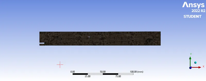
The model is downloaded in the challenge page of the skill lync.
then the ansys fluent is opened,by double clik the geometry the space claim is started.
after the space claim interface is opened ,the model is imported in the space claim.
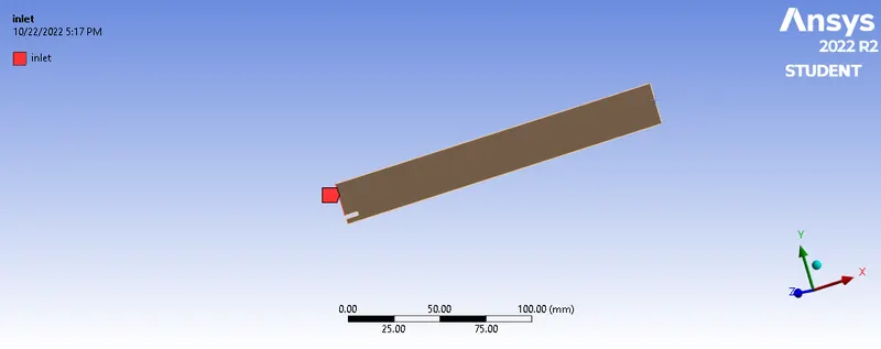
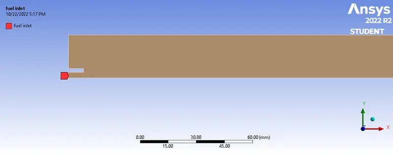
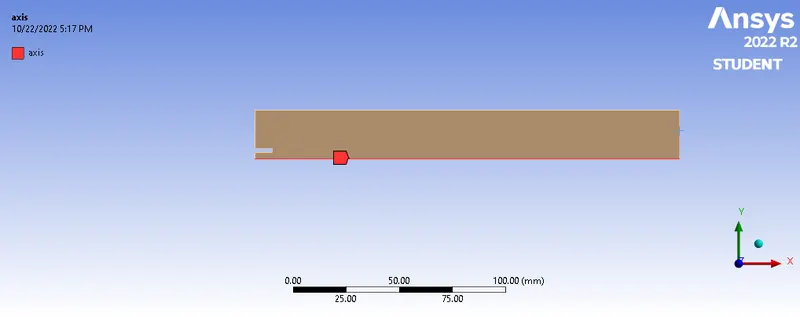
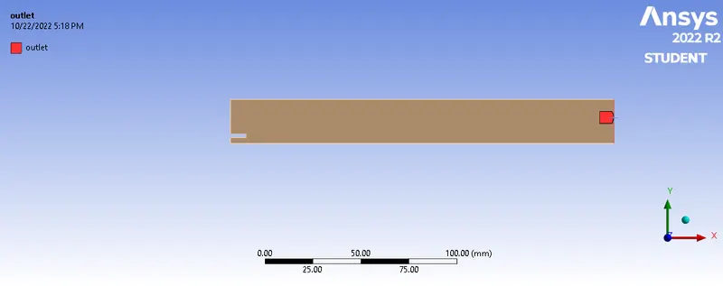


NOx Reasonably Available Control Technology (RACT)
The Clean Air Act Amendments of 1990 required major stationary sources of NOx to install and operate reasonably available control technology (RACT) by May 31, 1995. All of the New England States have developed and implemented NOx RACT regulations. Region-wide, these regulations have reduced NOx from stationary sources by more than 50% from 1990 levels. Below is a bar graph comparison of 1990 and 1996 NOx emissions from large stationary sources.
Ozone Transport Region (OTR) NOx Cap and Allowance Trading Program:
The Ozone Transport Region includes Maine, New Hampshire, Vermont, Massachusetts, Connecticut, Rhode Island, New York, New Jersey, Pennsylvania, Maryland, Delaware, the northern counties of Virginia, and the District of Columbia
Emissions from utilities in New England have decreased 57% from 1990 to 1996 as a result of the OTC NOx Cap and trade program.
EPA's Ozone Transport NOx SIP Call:
The Ozone Transport Region (OTR) NOx Cap and Allowance Trading Program addresses emissions in the northeast states, however, long-range ozone transport involves large NOx emission sources outside of the OTR.
CONCLUSION:
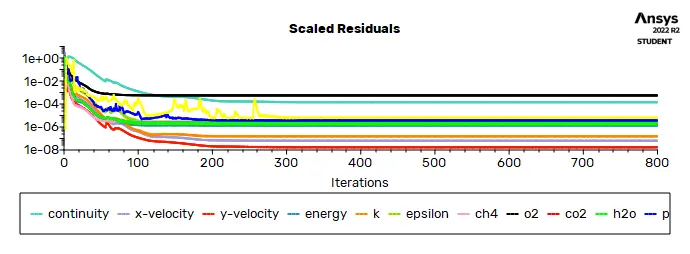
The simulation of the combustion of natural gas by using this ansys fluent for determing the mass fraction of the pollutants like ch4,co2,n2 and so on.
these are determined by the help of the NOX and SOOT is simulated properly and sucessfully.