Week 10 - Simulating Combustion of Natural Gas.
Introduction:-
The combustion is defined as a chemical reaction in which a hydrocarbon fuel reacts with an oxidant to form products, accompanied with the release of energy in the form of heat. Being the integral part of various engineering applications like internal combustion engines, furnace, power station combustors, combustion exhibits itself as a wide domain during the design, analysis and performance characterics stages of the above mentioned applications. In order to solve the complex equations from chemical kinetics and to yield information about the reaction mechanism proper physical modeling has to be done. In this project, the combustion process is simulated with the help of CFD software ANSYS fuent. When the combustion is incomplete, various pollutants are formed, some pollutants are carbon dioxide, carbon monoxide, lead, nitric oxide. In this project, the formation of pollutants from NOx emission which mainly consists of No, No2, N20 and soot formation which is a mass of impure carbon particles is simulated and the variation of mass fraction of pollutants from NOx emission and soot formation with the addition of water into the fuel in studied.
Modeling approach :-
CAD clean up/Pre-process-SpaceClaim - Import the geometry which is given. Split the geometry as it is axisymmetric. Convert the 3D geometry into 2D geometry by copying the phase and paste it.
Meshing :-Apply the elements size about 1 mm , Apply close proximity and give the proper name selection.
Setup :- In this section, we set up the steady state simulation. Apply turbulance model accordingaly. Apply species phase. Apply boundary condition. Apply report definition. Initialize the simulation and apply certain amount of iterations.
Solution :- we get the report definition of soot and NOx pollutant.
Result :- Plot the temperature contour and mass fraction contour of CH4, CO, CO2, H2O, O2, N2 , NOx, soot. Plot the graphical variation of mass fraction of these species.
CAD modeling :-
Import the geometry given.
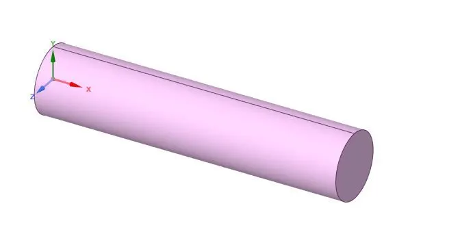
Cut the body and make the 3D geometry into 2D geometry.

Meshing :-
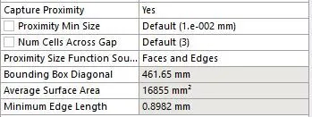
element size = 1mm
no of the element = 34864

enable capture proximity
Element metric :-
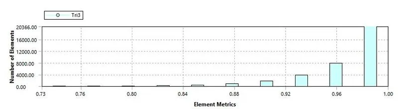
Here we can see that maximum elements have the higher quality in the range of 0.75 - 1.
Apply name selection accordingaly.
Air-inlet
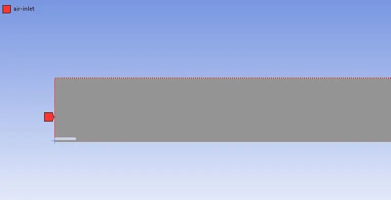
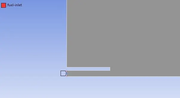
Fuel-inlet
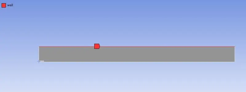
wall
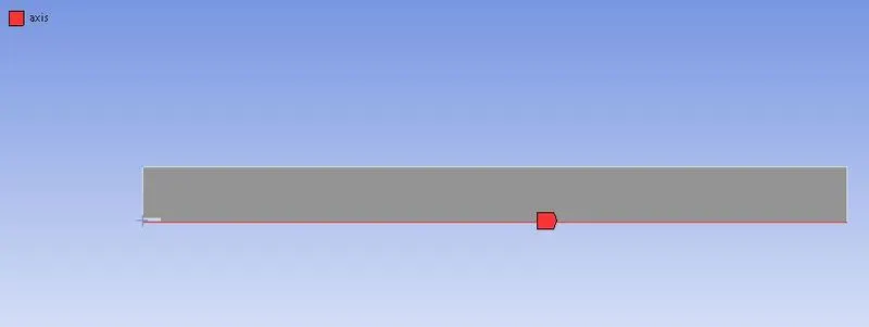
axis
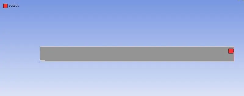
outlet
Setup :-
type of simulation = Steady state simulation
Solver
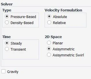
Turbulance model = kε - standard - standard wall function
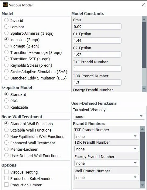
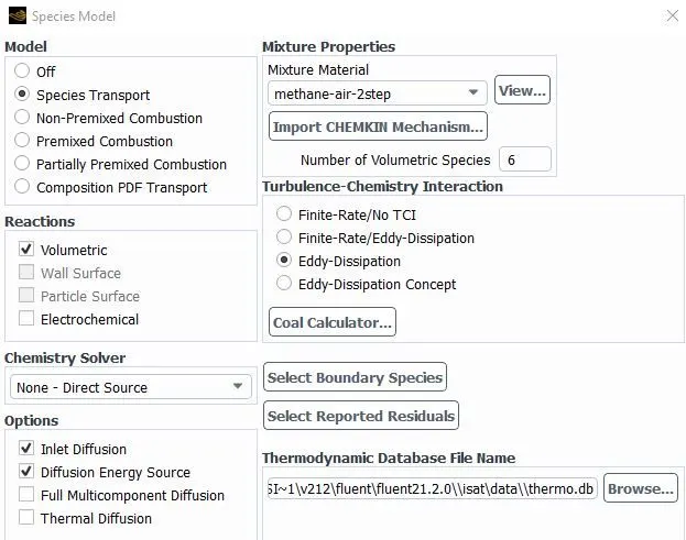
Set species model to species transport. Take mixture Methane - air - 2step. Set Eddy Dissipation as Turbulance chemistry interaction.
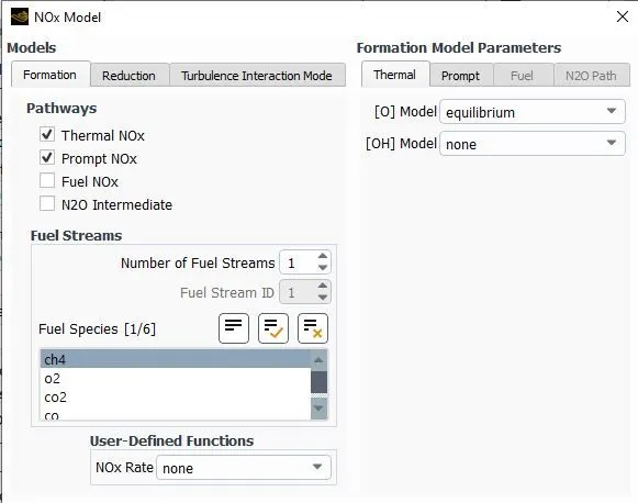
Enable NOx model. Enable thermal NOx and Prompt NOx.
Enable soot model. Select one step model.
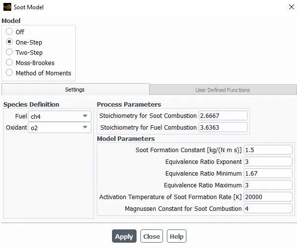
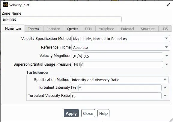
Apply boundary condition.
Velocity at air-inlet = 0.5 m/s
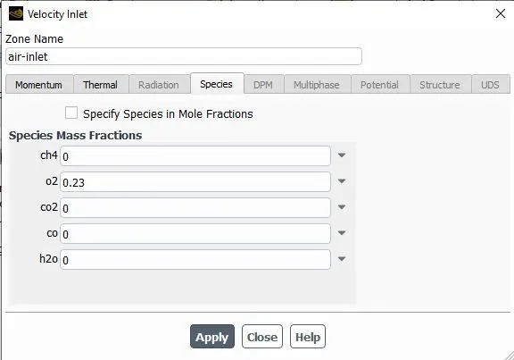
O2 mass fraction = 0.23
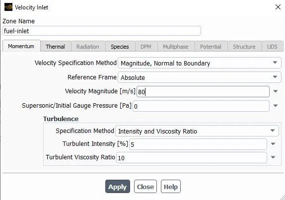
Velocity at fuel-inlet = 80 m/s
CH4 mass fraction = 1
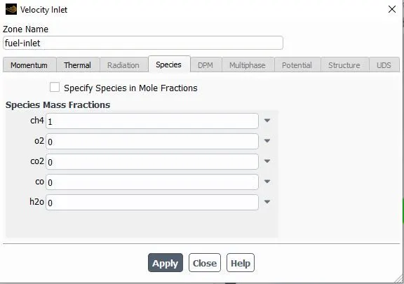
Outlet = pressure outlet.
Apply report definition for NOx and soot mass fraction at outlet.
Apply hybrid initialization and 800 iterations.
Solution :-
residuals
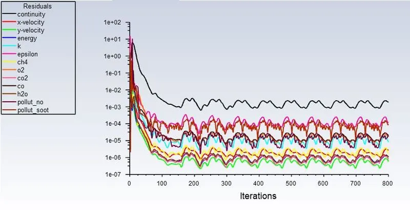
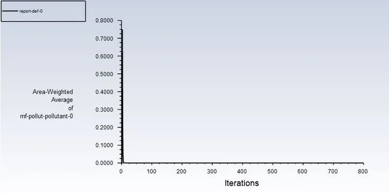
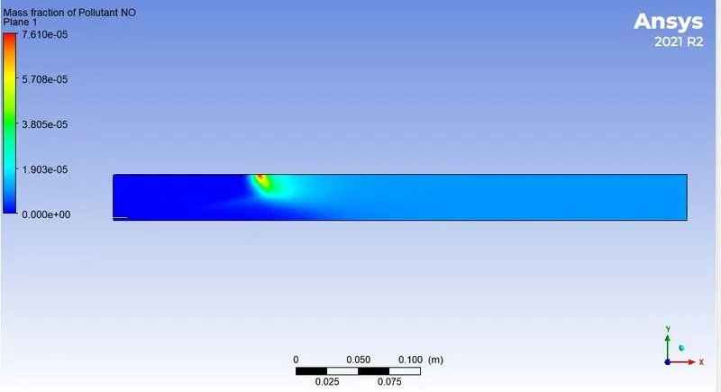
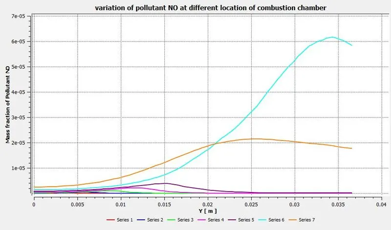
Mass fraction of NOx emmision = 1.55e-5
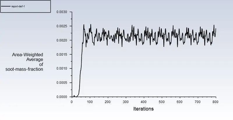
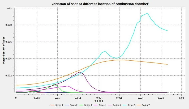
Mass fraction of soot emmision = 0.002417
Results :-
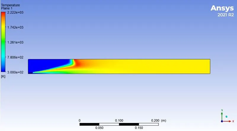
Temperature contour
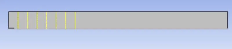
Line prompts at different locations
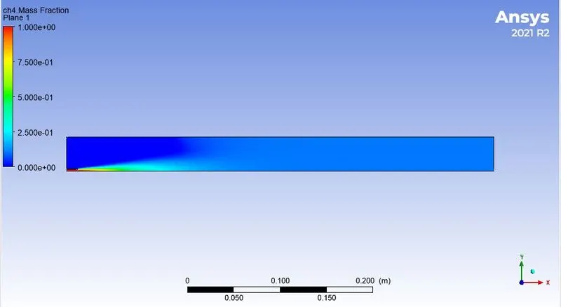
Mass fraction of CH4
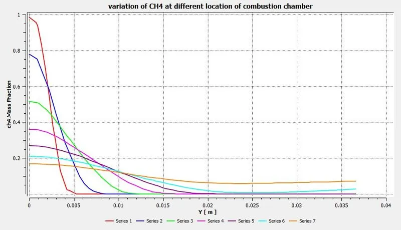
Graphical variation of CH4 at different location of the combustion chamber
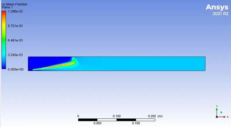
Mass fraction of CO
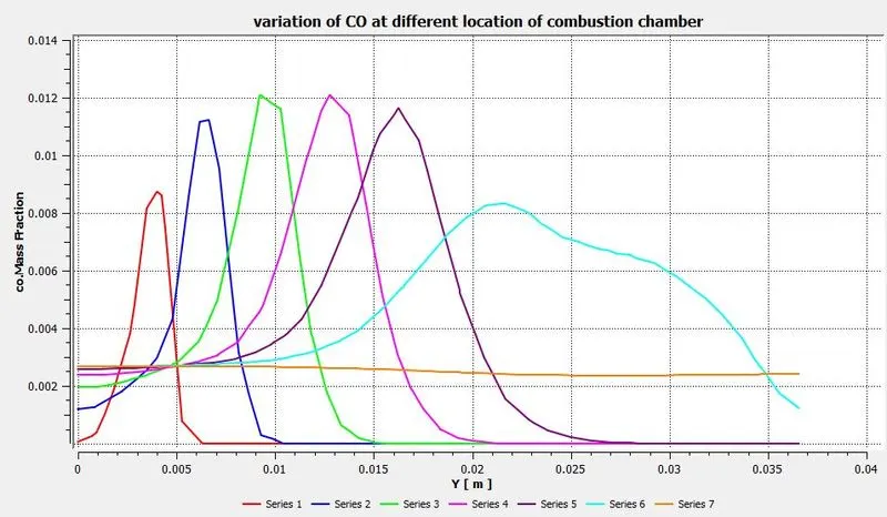
Graphical variation of CO at different location of the combustion chamber
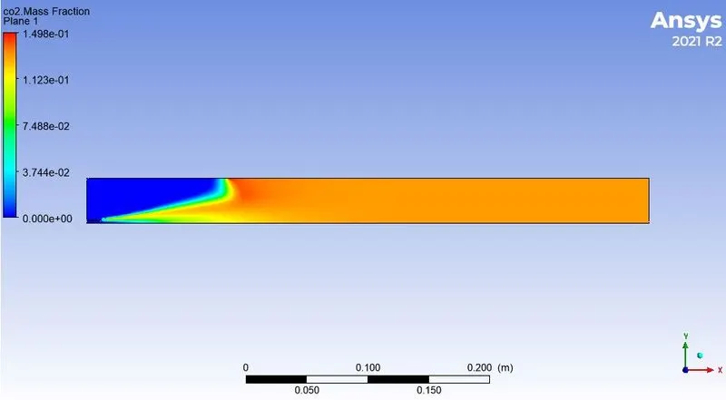
Mass fraction of CO2
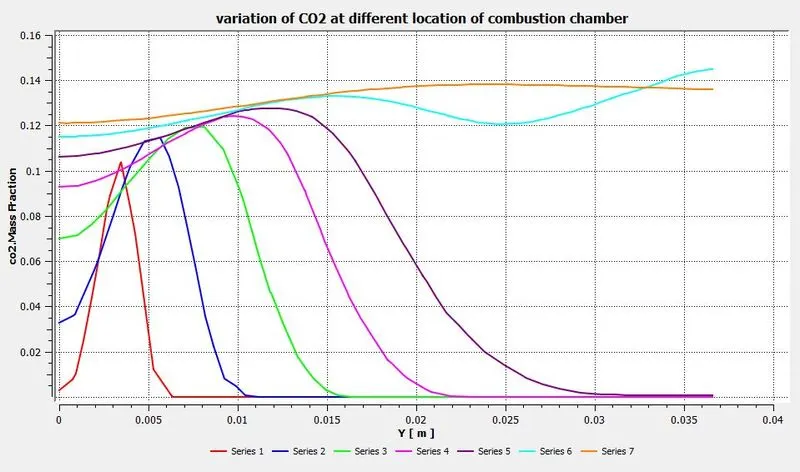
Graphical variation of CO2 at different location of the combustion chamber
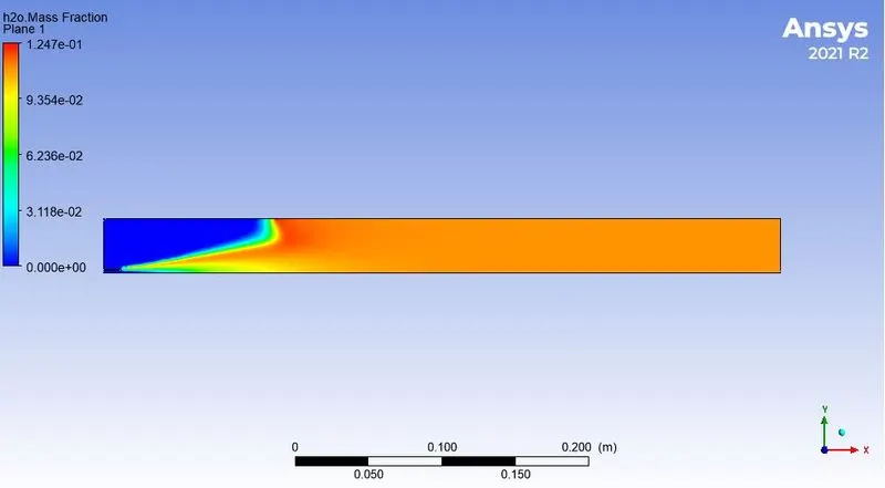
Mass fraction of H2O
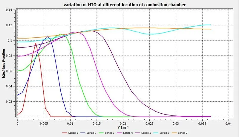
Graphical variation of H2O at different location of the combustion chamber
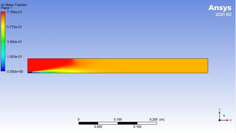
Mass fraction of N2
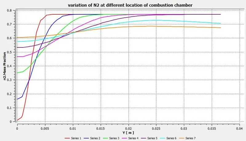
Graphical variation of N2 at different location of the combustion chamber
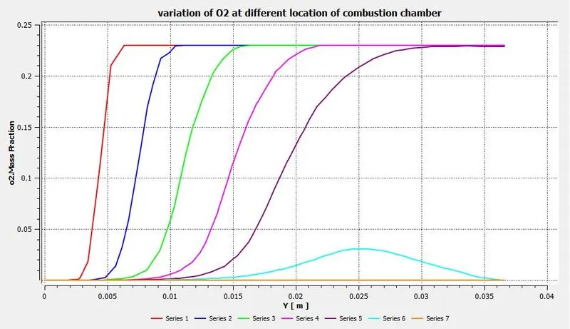
Mass fraction of O2
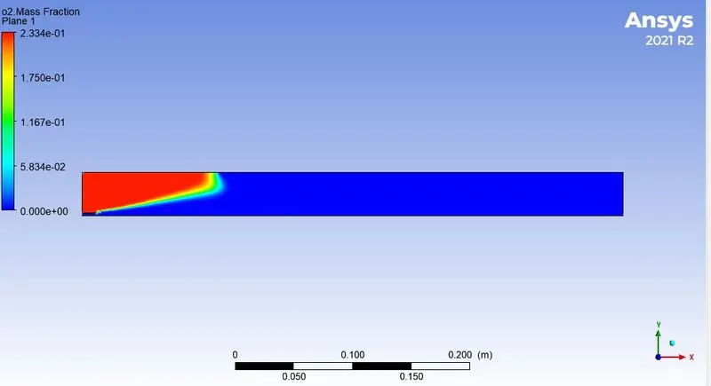
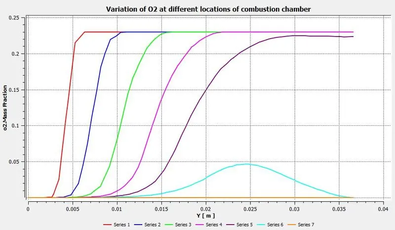
Graphical variation of O2 at different location of the combustion chamber
Mass fraction of NOx emmision
Graphical variation of NOx at different location of the combustion chamber
Mass fraction of soot emmision
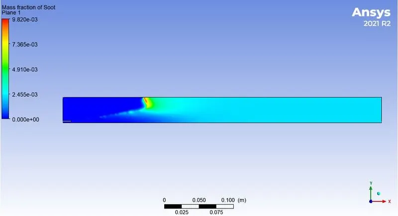
Graphical variation of soot at different location of the combustion chamber
PART - 2
i) 10% added water by mole
type of simulation = Steady state simulation
Solver
Turbulance model = kε - standard - standard wall function
Set species model to species transport. Take mixture Methane - air - 2step. Set Eddy Dissipation as Turbulance chemistry interaction.
Enable NOx model. Enable thermal NOx and Prompt NOx.
Enable soot model. Select one step model.
Apply boundary condition.
Velocity at air-inlet = 0.5 m/s
O2 mass fraction = 0.23
Velocity at fuel-inlet = 80 m/s
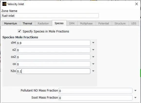
CH4 mole fraction = 0.9 , H2O mole fraction = 0.1
Outlet = pressure outlet.
Apply report definition for NOx and soot mass fraction at outlet.
Apply hybrid initialization and 800 iterations.
Solution :-
residuals
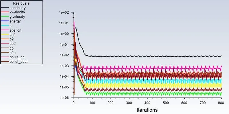
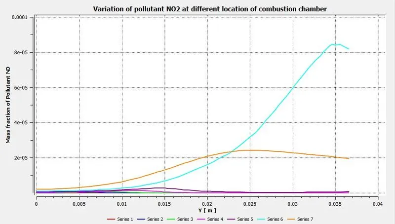
Mass fraction of NOx emmision = 1.05e-5
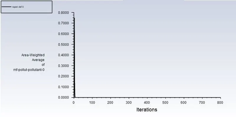
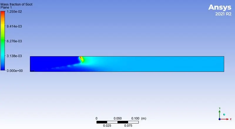
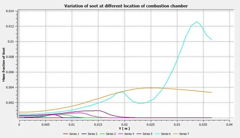
Mass fraction of soot emmision = 0.002163
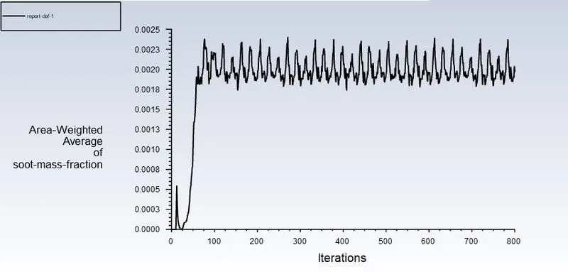
Results :-
Temperature contour
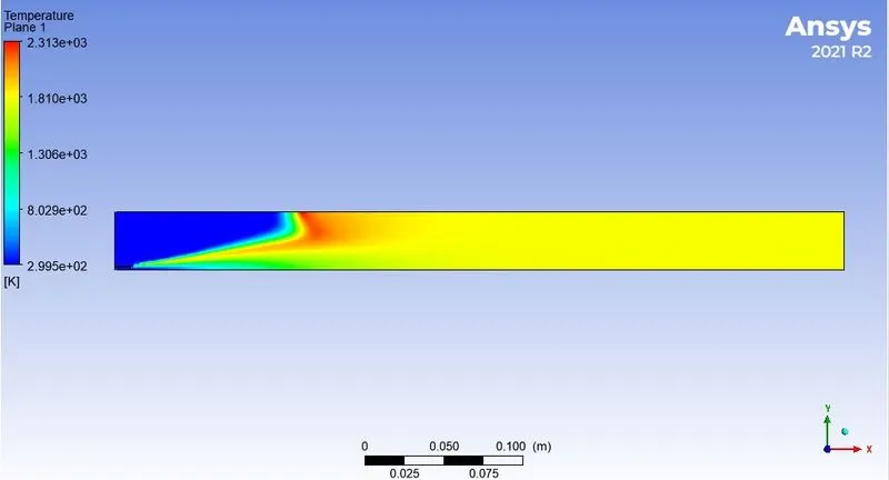
Line prompts at different locations
Mass fraction of CH4
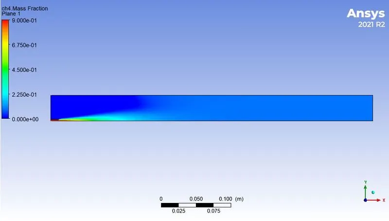
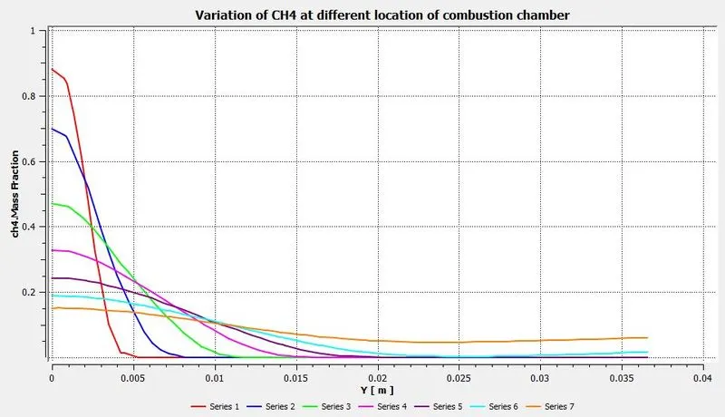
Graphical variation of CH4 at different location of the combustion chamber
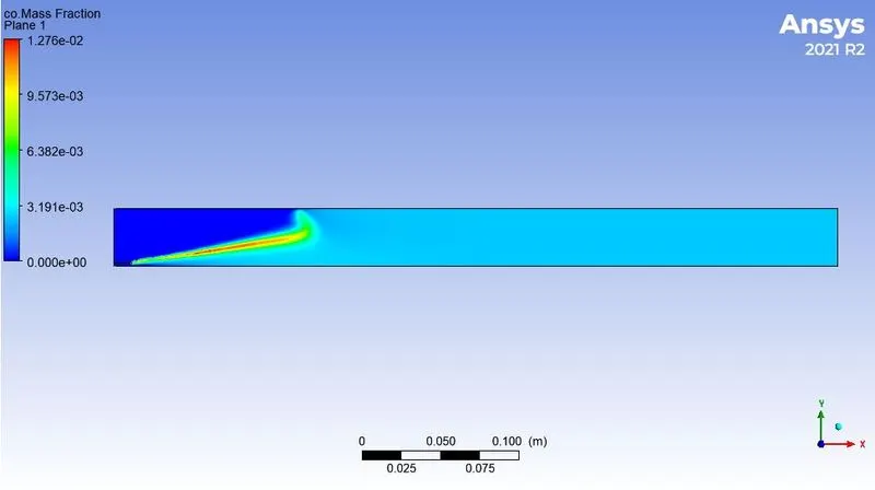
Mass fraction of CO
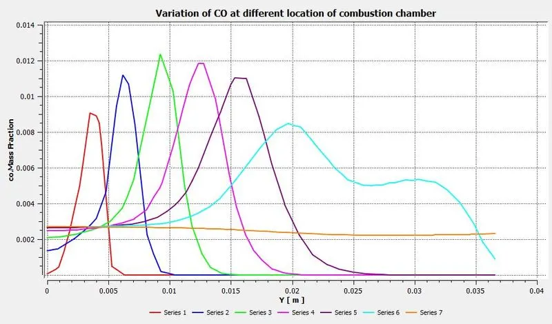
Graphical variation of CO at different location of the combustion chamber
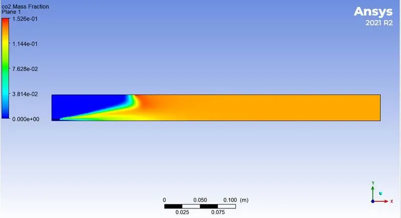
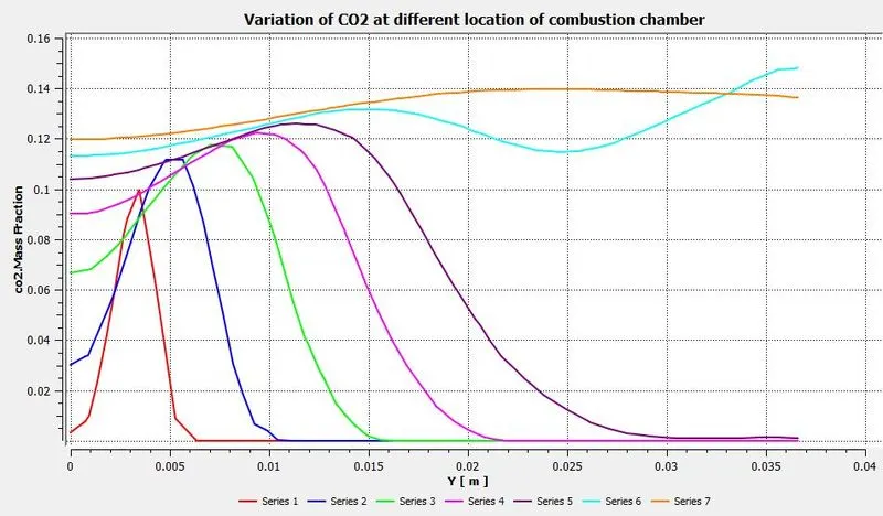
Mass fraction of CO2
Graphical variation of CO2 at different location of the combustion chamber
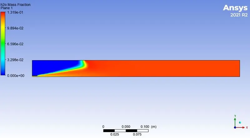
Mass fraction of H2O
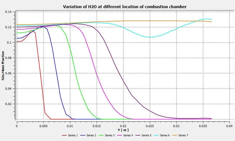
Graphical variation of H2O at different location of the combustion chamber
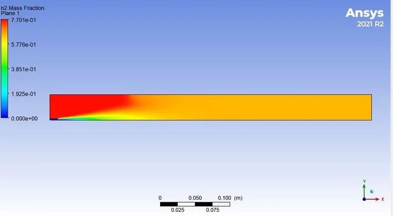
Mass fraction of N2
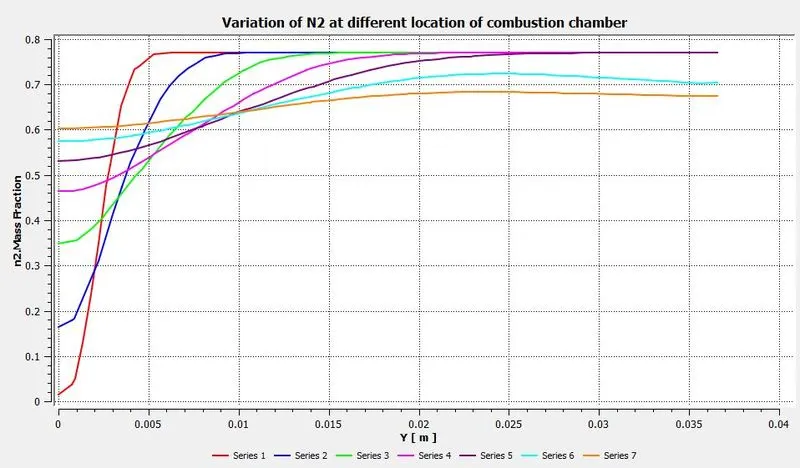
Graphical variation of N2 at different location of the combustion chamber
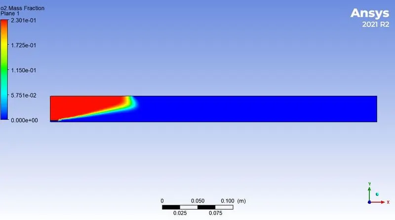
Mass fraction of O2
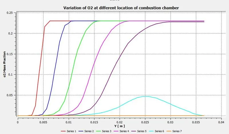
Graphical variation of O2 at different location of the combustion chamber
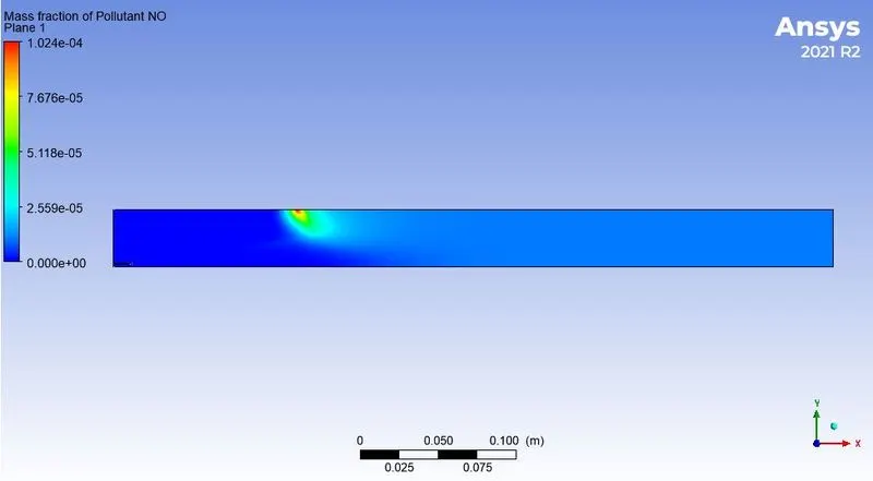
Mass fraction of NOx emmision
Graphical variation of NOx at different location of the combustion chamber
Mass fraction of soot emmision
Graphical variation of soot at different location of the combustion chamber
ii) 20% added water :-
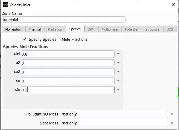
Apply boundary condition.
Velocity at air-inlet = 0.5 m/s
O2 mass fraction = 0.23
Velocity at fuel-inlet = 80 m/s
CH4 mole fraction = 0.8 , H2O mole fraction = 0.2
Outlet = pressure outlet.
Apply report definition for NOx and soot mass fraction at outlet.
Apply hybrid initialization and 800 iterations.
Solution :-
residuals
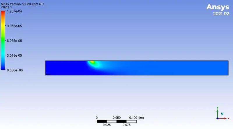
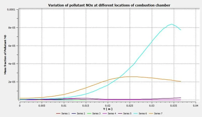
Mass fraction of NOx emmision = 1.00e-5
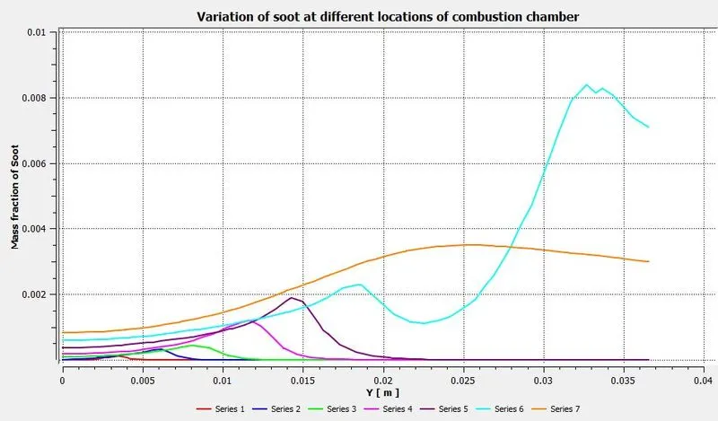
Mass fraction of soot emmision = 0.001865
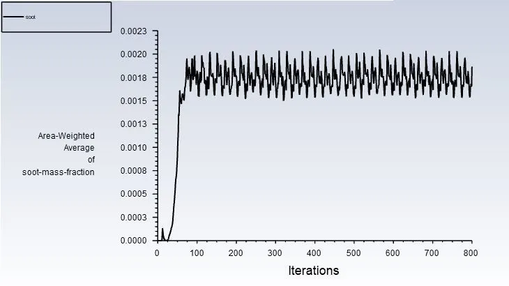
Results :-
Temperature contour
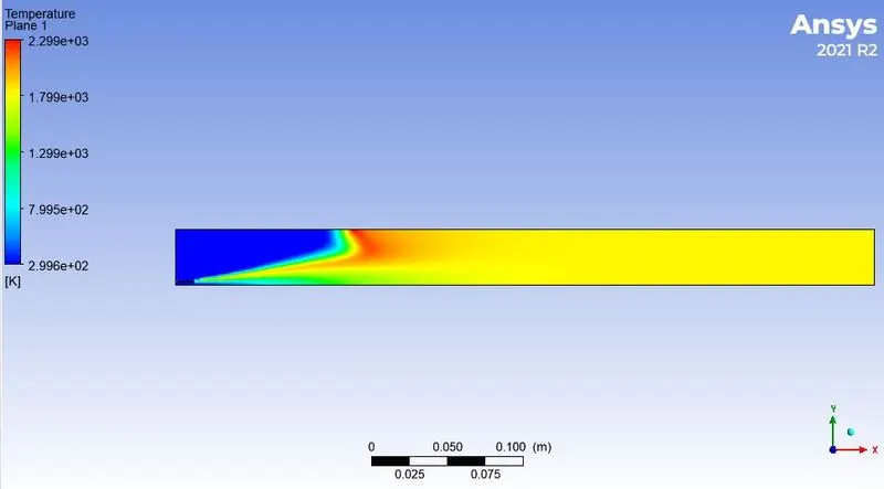
Line prompts at different locations
Mass fraction of CH4
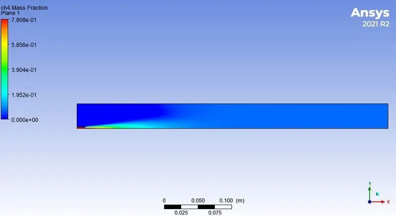
Graphical variation of CH4 at different location of the combustion chamber
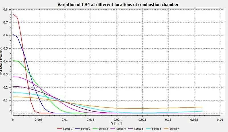
Mass fraction of CO
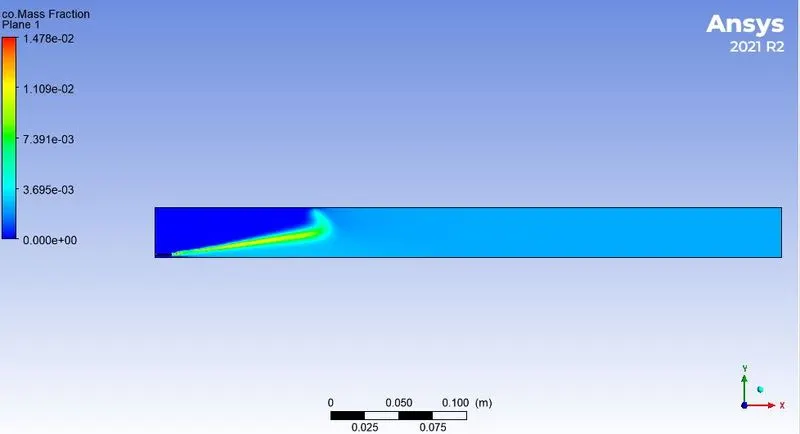
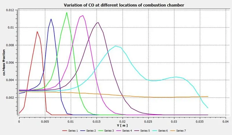
Graphical variation of CO at different location of the combustion chamber
Mass fraction of CO2
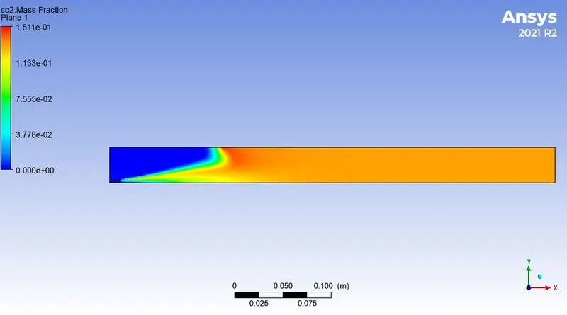
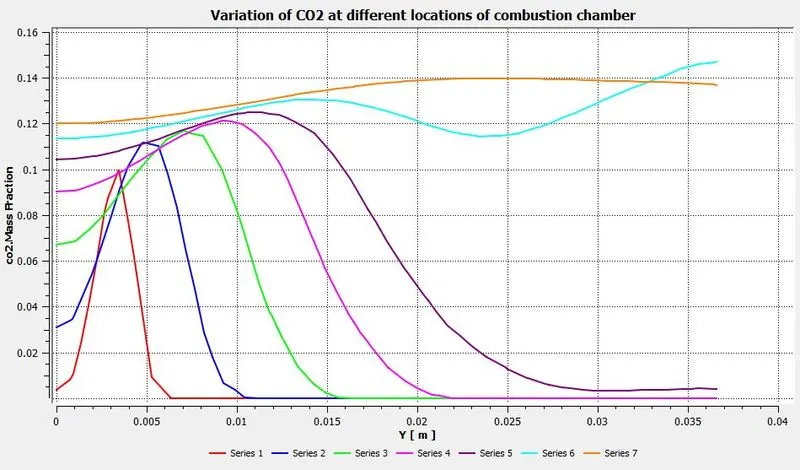
Graphical variation of CO2 at different location of the combustion chamber
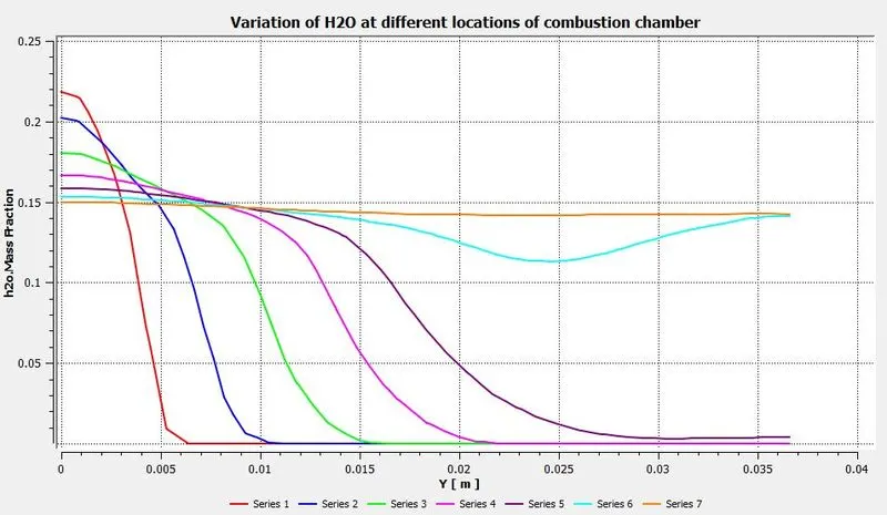
Mass fraction of H2O
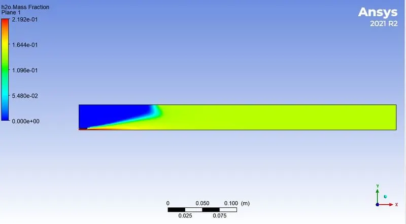
Graphical variation of H2O at different location of the combustion chamber
Mass fraction of N2
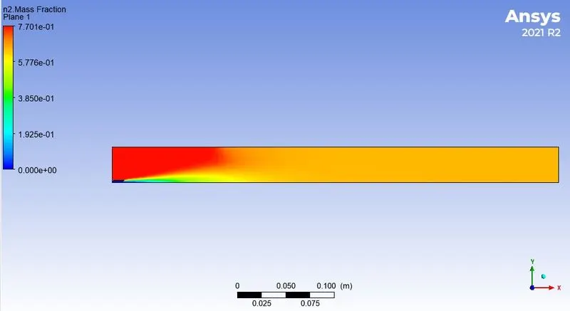
Graphical variation of N2 at different location of the combustion chamber
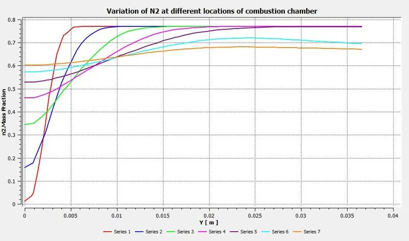
Mass fraction of O2
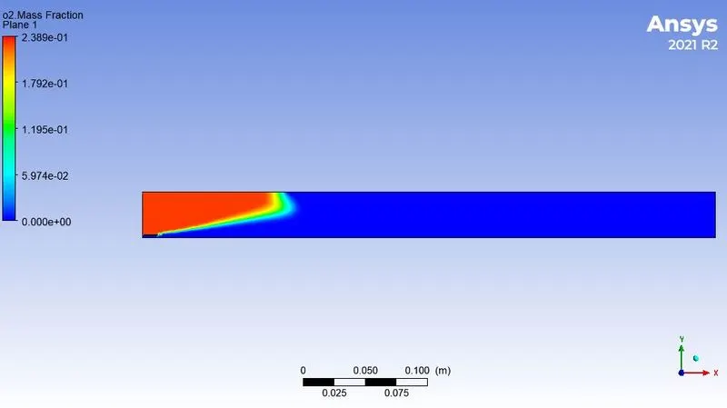
Graphical variation of O2 at different location of the combustion chamber
Mass fraction of NOx emmision
Graphical variation of NOx at different location of the combustion chamber
Mass fraction of soot emmision
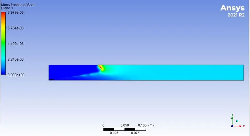
Graphical variation of soot at different location of the combustion chamber
iii) 30% added water :-
Apply boundary condition.
Velocity at air-inlet = 0.5 m/s
O2 mass fraction = 0.23
Velocity at fuel-inlet = 80 m/s
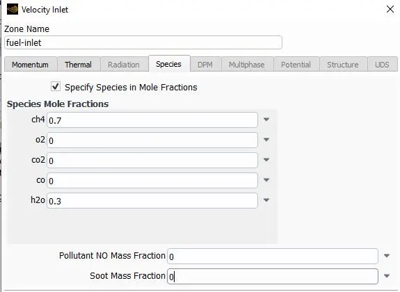
CH4 mole fraction = 0.7 , H2O mole fraction = 0.3
Outlet = pressure outlet.
Apply report definition for NOx and soot mass fraction at outlet.
Apply hybrid initialization and 800 iterations.
Solution :-
residuals
Mass fraction of NOx emmision = 8.59e-6
Mass fraction of soot emmision = 0.001578
Results :-
Temperature contour
Line prompts at different locations
Mass fraction of CH4
Graphical variation of CH4 at different location of the combustion chamber
Mass fraction of CO
Graphical variation of CO at different location of the combustion chamber
Mass fraction of CO2
Graphical variation of CO2 at different location of the combustion chamber
Mass fraction of H2O
Graphical variation of H2O at different location of the combustion chamber
Mass fraction of N2
Graphical variation of N2 at different location of the combustion chamber
Mass fraction of O2
Graphical variation of O2 at different location of the combustion chamber
Mass fraction of NOx emmision
Graphical variation of NOx at different location of the combustion chamber
Mass fraction of soot emmision
Graphical variation of soot at different location of the combustion chamber
Conclusions:-
we can find that small addition of water in fuel plays an important role in pollution control and less production of nox and soot material. Emission of nox and soot are potentially harmful to environment and human health. The general observation from the combustion analysis tells that the level of nox and soot decreases with increase in water content inside fuel. The temperature also decreases at the outlet section due to this factor. Among all the cases 30% addition of water content inside fuel is found to be best and also supports the claim to reduce the pollutants effectively and increase the life span of engine.