Week 10 - Simulating Combustion of Natural Gas.
Aim: Perform the combustion simulation on the combustor model and plot the variation of mass fraction of different species in the simulation using line probes at different locations of the combustor as shown below, we need to plot for CO2, H2o, CH4, N2, O2, NOx formtaion and soot formation.
In the scond part, we will add water into fuel from 5 to30% by mole and observe the effect of it on the results.
Introduction: Combustion is a chemical reaction in which a hydrocarbon reacts with oxygen to form products , also it releases energy in heat form.
CFD modelling of combustion depends upon proper selection and implementation of model suitable to faithfully represent the complex physical and chemical phenomenon associated with any combustion process.
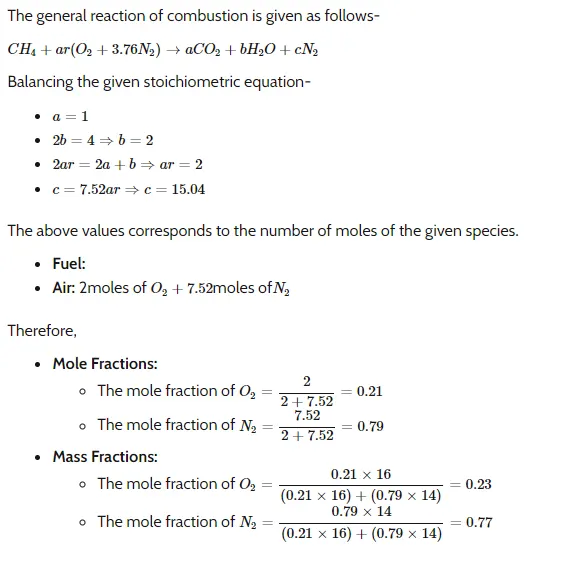
Combustion reactions:
Problem statement:
Fuel species is methane and fluid is air, which contains a mixture of oxygen and nitrogen.
Air velocity is 0.5 m/s.
Fuel velocity at inlet is 80 m/s.
Part I : Combustion simulation to get mass fraction of different species like CO2, H2O, CH4, N2, O2, NOx and SOOT formation.
PArt II : Adding water in fuel from 5% to 30%. by mole and observing .
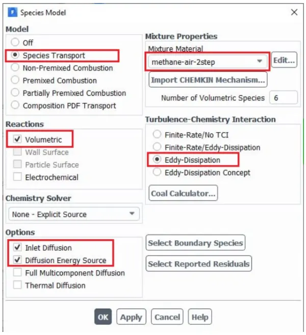
We are using metahne-air-2step method as it allows to add water in air or fuel.
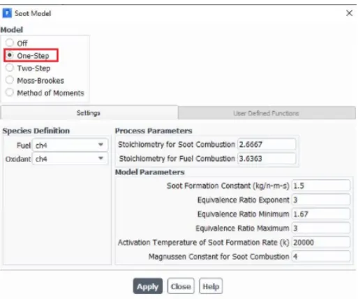
For soot formation, use one step soot model.
SpaceClaim model:
1. Combustion model
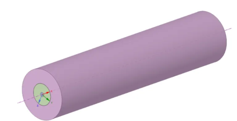
We are going to use axi-symetric model as modelling 3D this geometry will take lot of time and computational space and memory.
As gradients along the circumference are going to be zero, we can assume this. The properties will differ only in radial direction. On 360 degrees, properties will get repeated at theta angle.
For that we will assemble all components first then we cut the body in 2 halves, then again 2 halves.
Then we copy the faces in x-y plane and paste it separately in New design. Now, this geometry is ready for further process.

2. Boundaries:
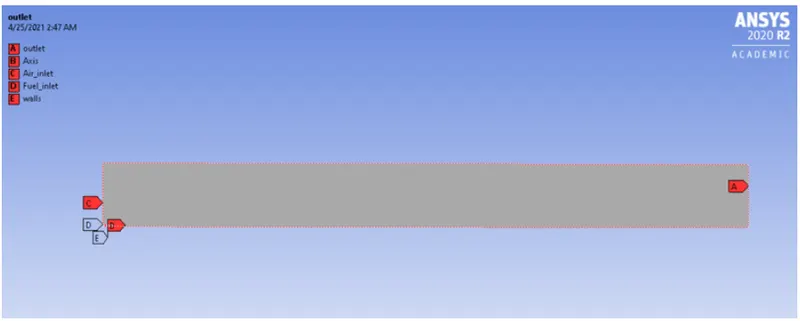
Using named selection, below are boundaries made ,
1. axis
2. walls
3. inlet
4. outlet
5. air inlet
6. fuel inlet
3. Meshing:
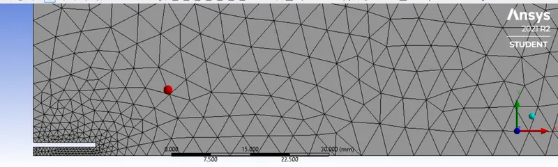
Element size: 2 mm
Method: All triangles
Sizing: Proximity on
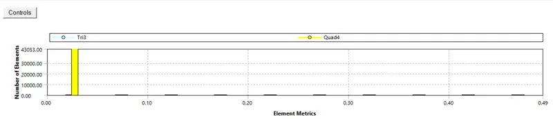
Skewnes Mesh Quality
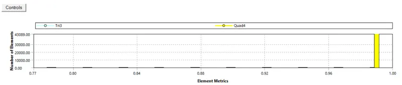
Orthogonal Quality
No of nodes: 3334
No. of elements: 6249
Simulation setup
Solver: Steady
Type: Pressure
Turbulence model: k-Epsilon
Enrgy: on
Species model :
4. Boundary conditions:
Air inlet
Velocity: 0.5 m/s
temperature: 300 K
Species mass fraction:
CH4 : 0
O2 : 0.23
CO2 : 0
H2O : 0
Fuel inlet
Velocity: 80 m/s
temperature: 300 K
Species mass fraction:
CH4 : 1
O2 : 0
CO2 : 0
H2O : 0
Outlet : Pressure : 0 Pa (Gauge pressure)
Solution method: SIMPLE
Initialisation : Hybrid
Time steps: 600
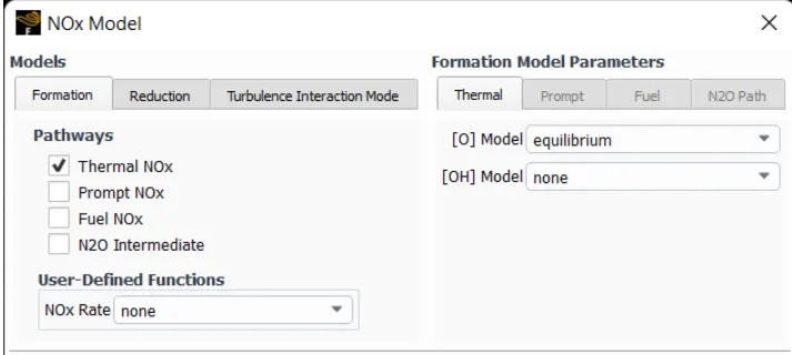
Post processing: We plot for CO2, H2O, CH4, N2, O2, NOx emissions & Soot formation.
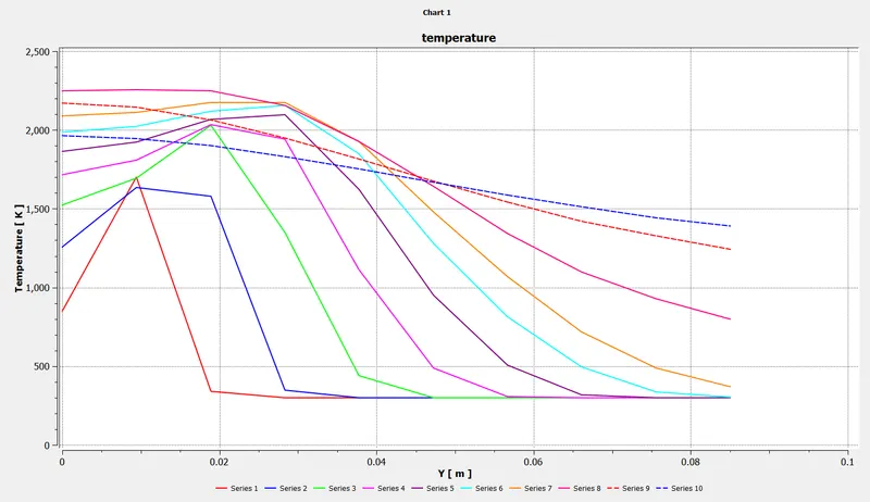
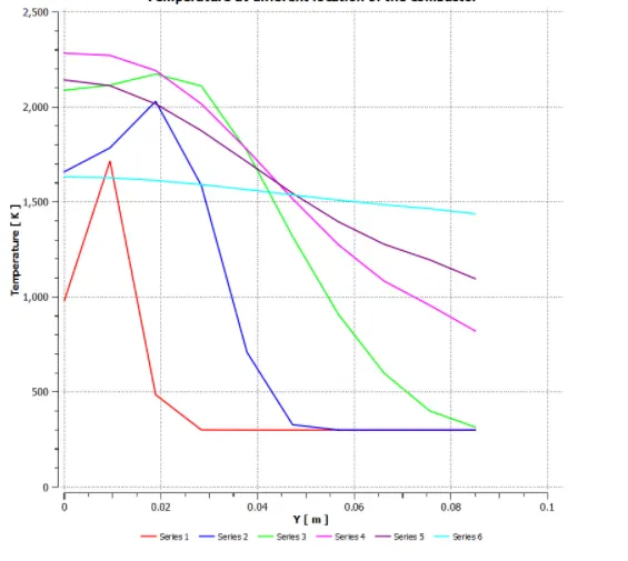
Charts at line probes
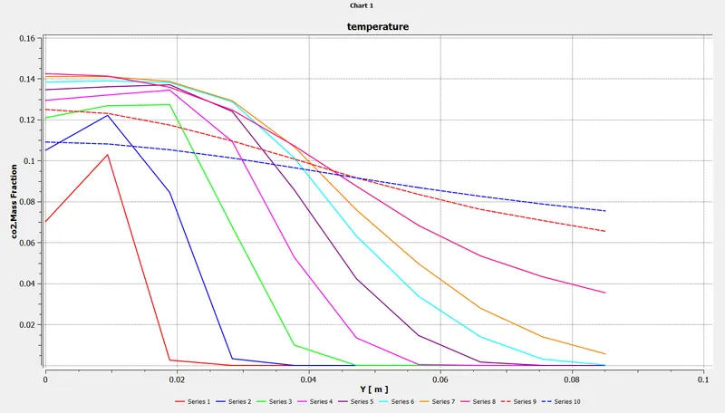
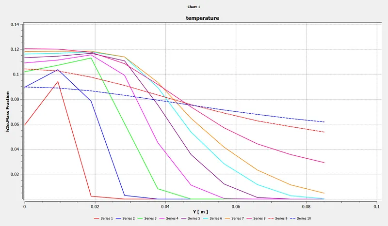
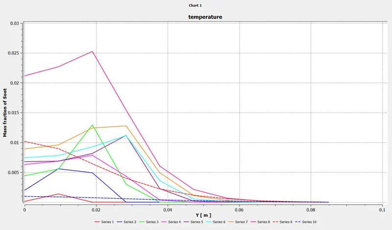
With the help of line probes, we can plot the variation of mass fraction at different locations.
For that we hvae to create lines at different locations as below,
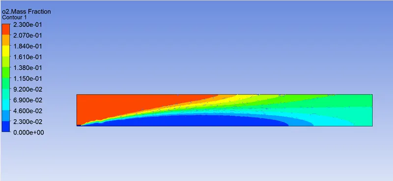
line 1: Two point method (0.05,0) (0.05,0.0852)
line 2: Two point method (0.1,0) (0.05,0.0852)
line 3: Two point method (0.15,0) (0.05,0.0852)
line 4: Two point method (0.20,0) (0.05,0.0852)
line 5: Two point method (0.25,0) (0.05,0.0852)
line 6: Two point method (0.3,0) (0.05,0.0852)
line 7: Two point method (0.35,0) (0.05,0.0852)
line 8: Two point method (0.45,0) (0.05,0.0852)
line 9: Two point method (0.6,0) (0.05,0.0852)
line 10: Two point method (0.7,0) (0.05,0.0852)
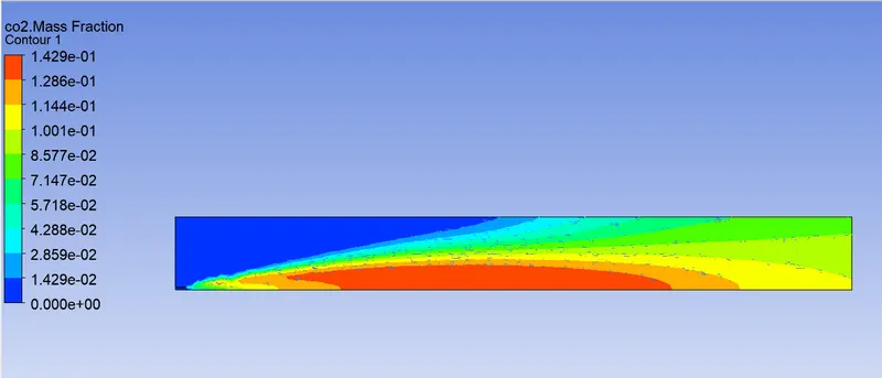
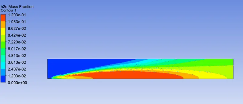
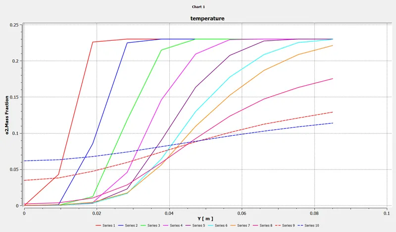
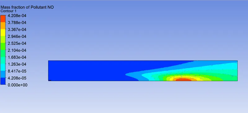
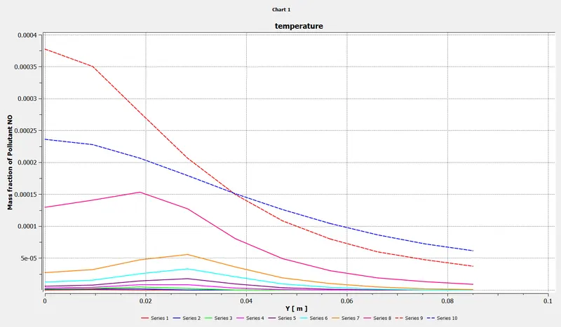
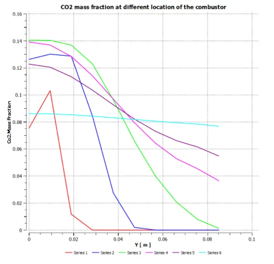
Variation of mass fraction of different species at above locations can be given by plots below,
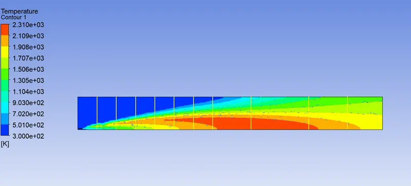
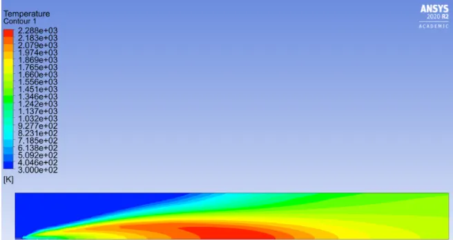
Temperature contour :
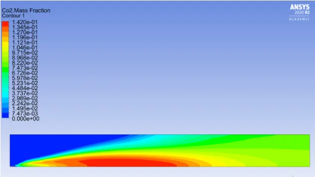
CO2 mass fraction :
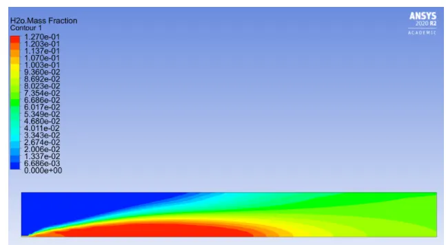
H2O mass fraction :
CH4 mass fraction :
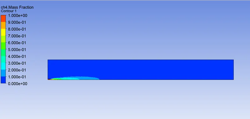
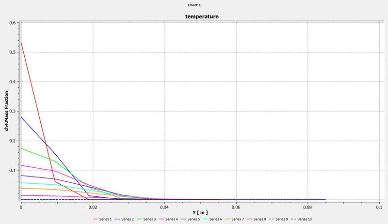
N2 mass fraction :
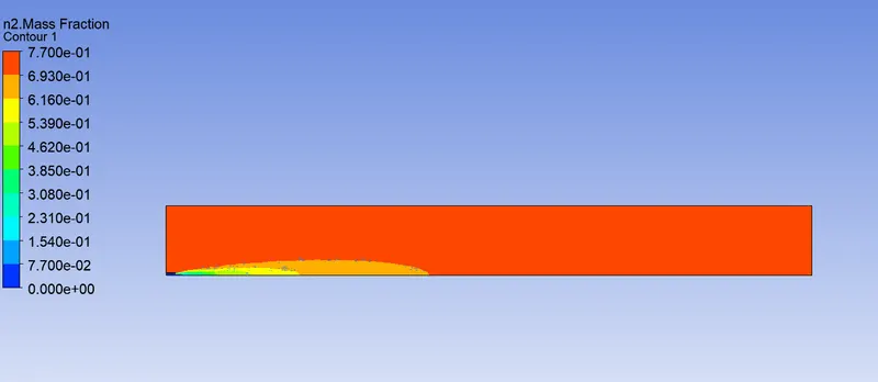
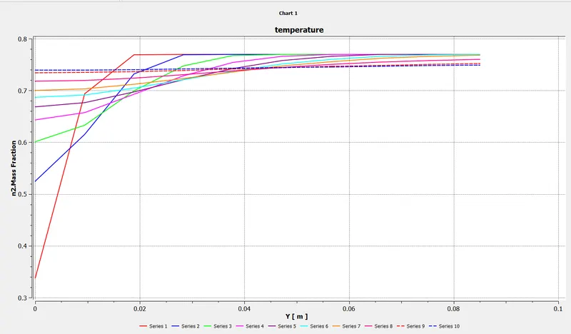
O2 mass fraction :
NOx mass fraction :
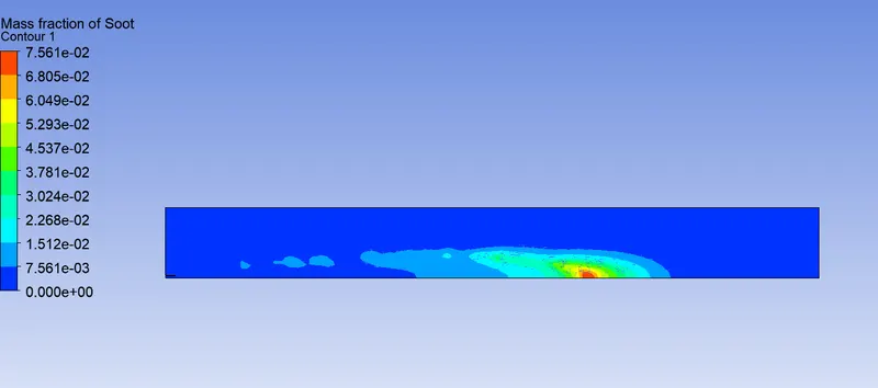
Soot formation mass fraction :
Part II : Supplying water to engine
To minimize the temperature peaks during the combustion process in diesel engines , hence NOx concentration in the exhaust gas can be done by means of supplying water into cylinder.
The emulasion supplied into the cylinder causes the increase of self-ignition delay which affects the flammable mixture becoming more homogeneous int he whole volume of the combustion chamber. The increased self ignition delay extends the time necessary to spread the injected fuel which results in fewer zones with not enough oxygen . This decreases intensity of soot and CO formation . Emulsifying mixture reduces local zones with temperature peaks which leads to deceasing nitrogen activity and NOx concentration.
1. 10% water addition
CO2 contour and mass fraction
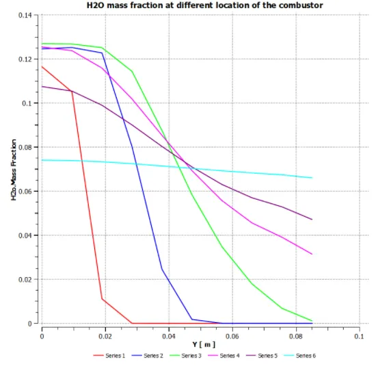
H2O contour and mass fraction chart
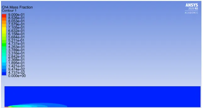
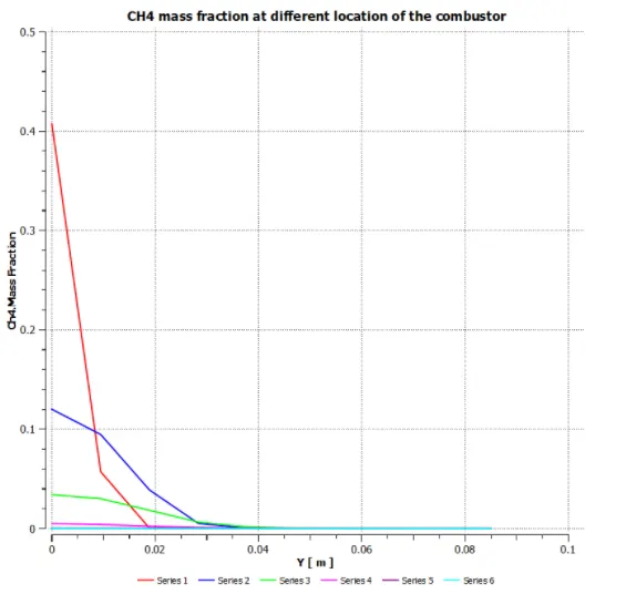
Ch4 contour and mass fraction
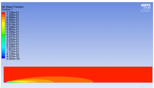
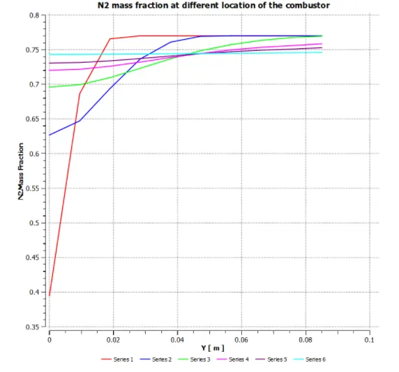
N2 contour and mass fraction
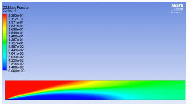
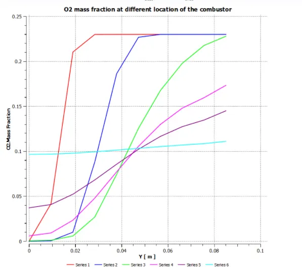
O2 contour and mass fraction
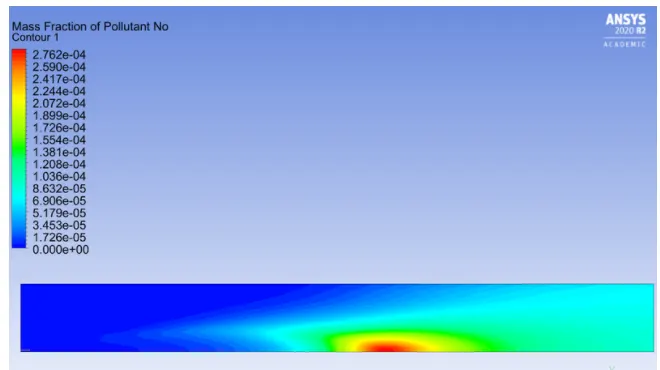
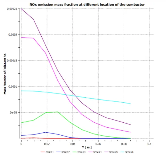
NOX emission contour and mass fraction
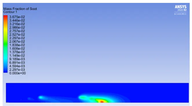
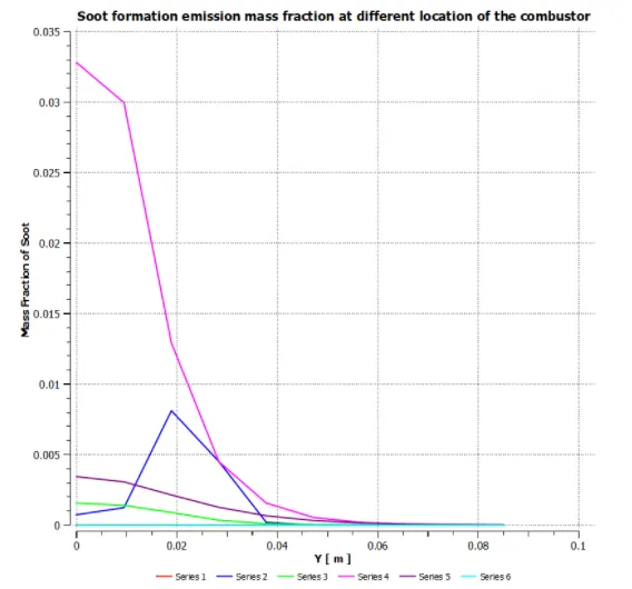
Soot formation contour and mass fraction
2. 20% water addition
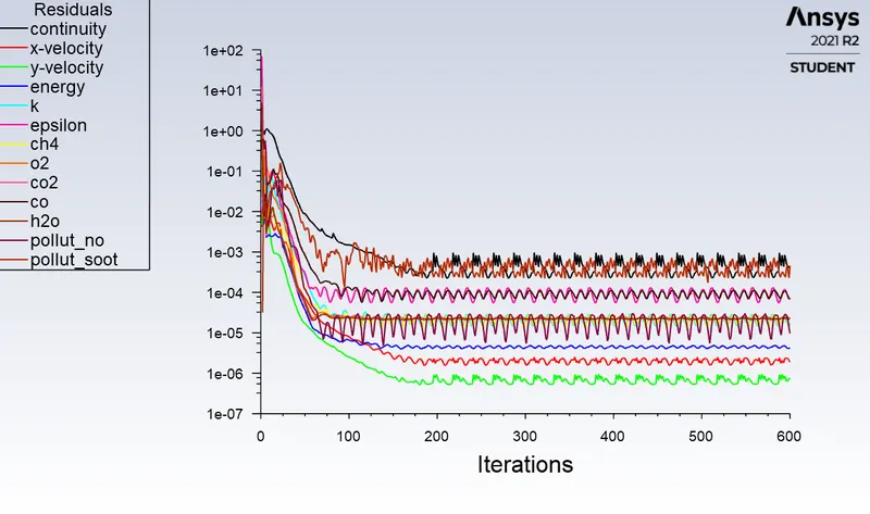
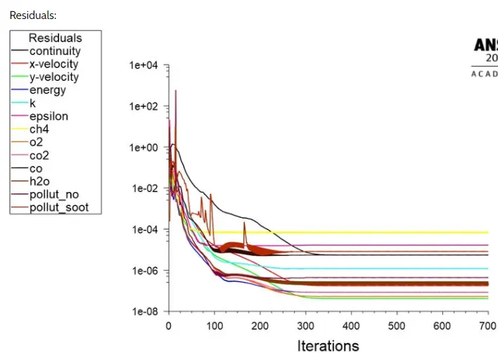
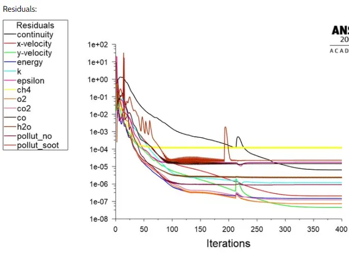
Residuals:
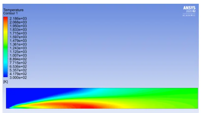
Temperature contour
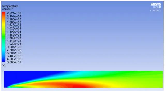
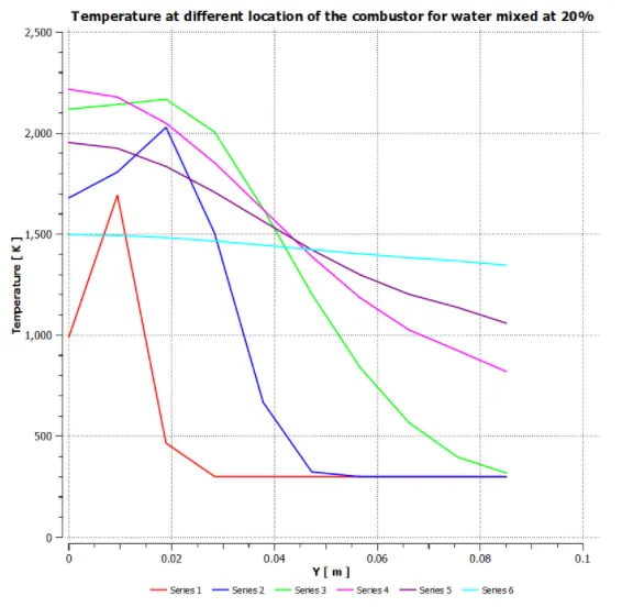
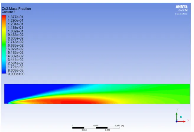
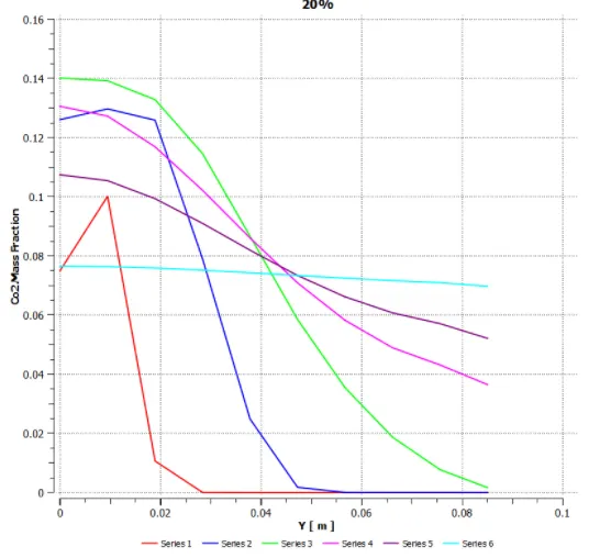
CO2 contour and mass fraction chart
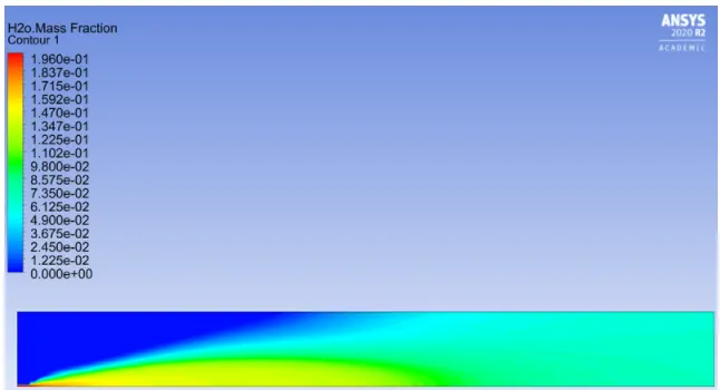
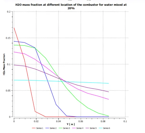
H2O contour and mass fraction chart
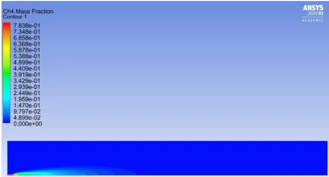
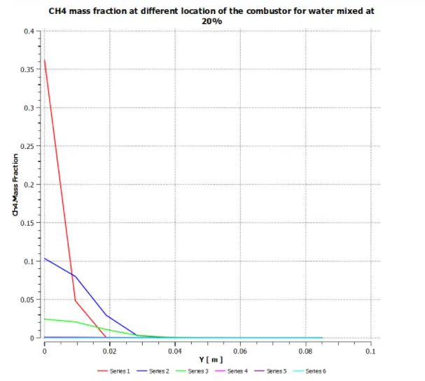
CH4 contour and mass fraction chart
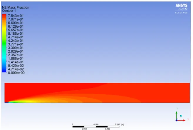
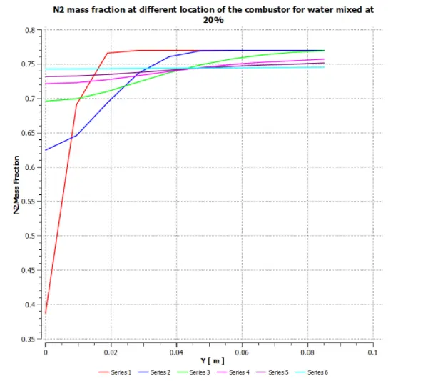
N2 contour and mass fraction chart
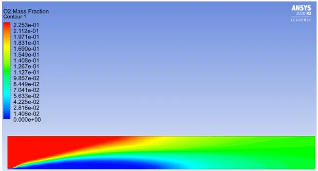
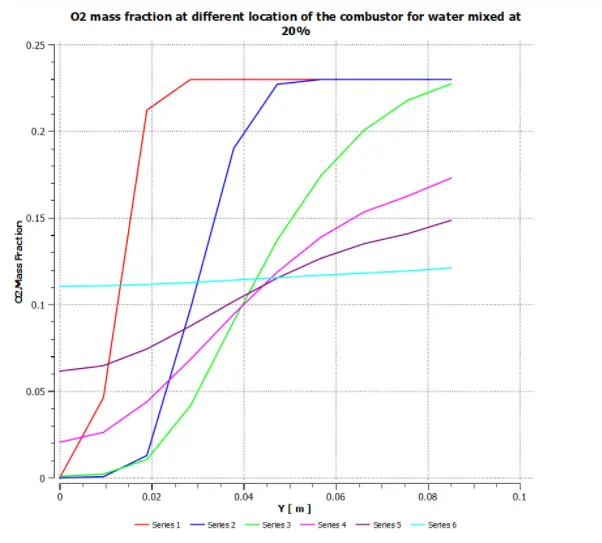
O2 contour and mass fraction chart
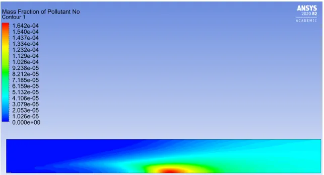
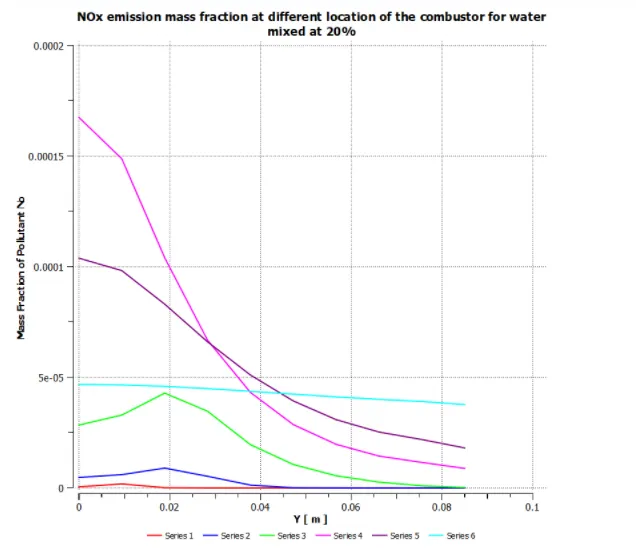
NOx contour and mass fraction chart
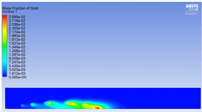
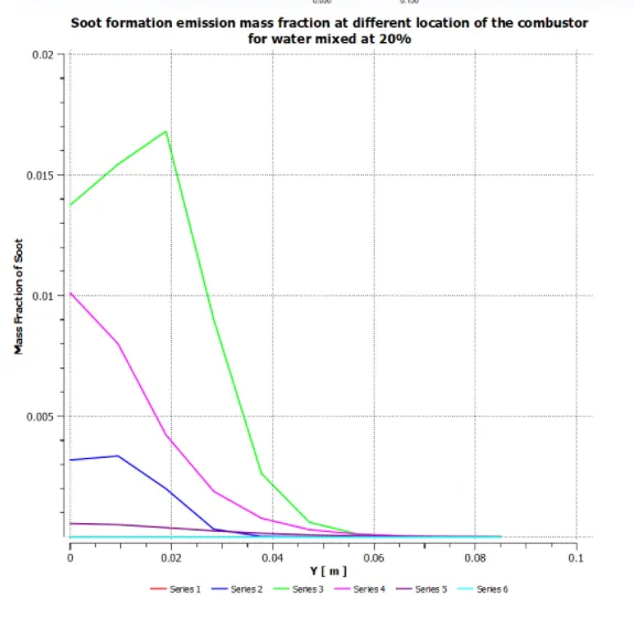
Soot contour and mass fraction chart
3. 30% water addition
Residuals:
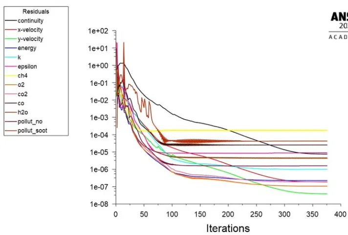
Temperature contour
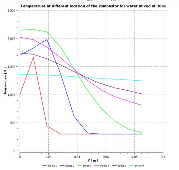
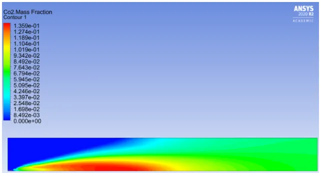
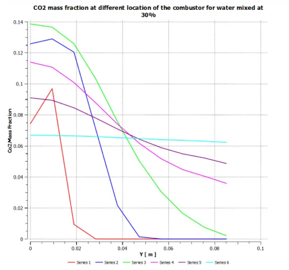
CO2 contour and mass fraction chart
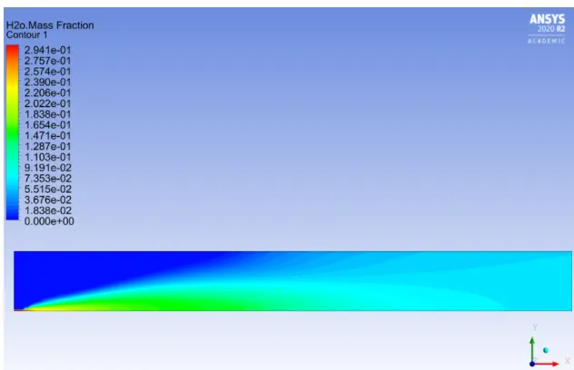
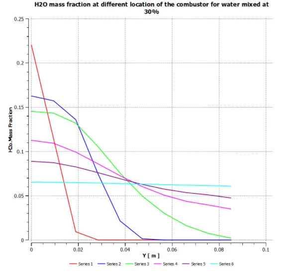
H2O contour and mass fraction chart
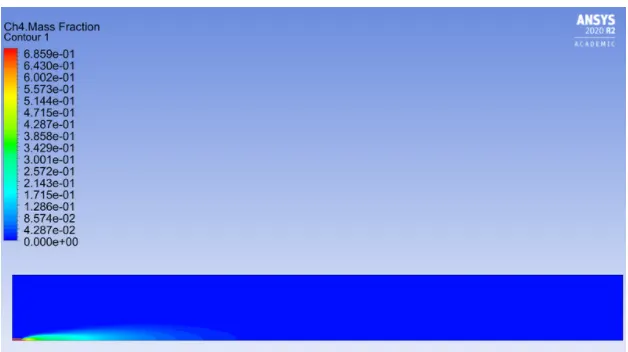
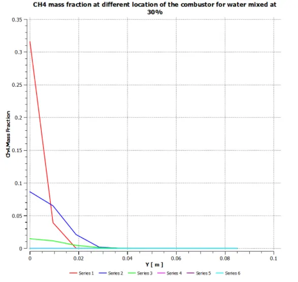
CH4 contour and mass fraction chart
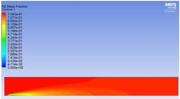
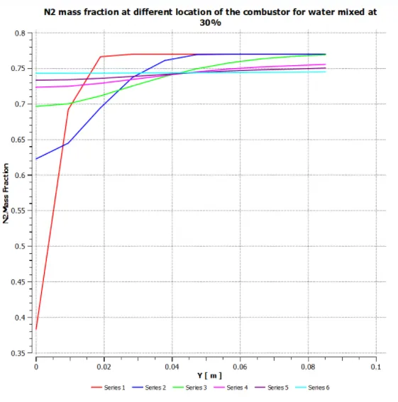
N2 contour and mass fraction chart
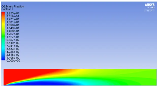
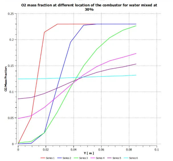
O2 contour and mass fraction chart
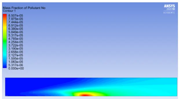
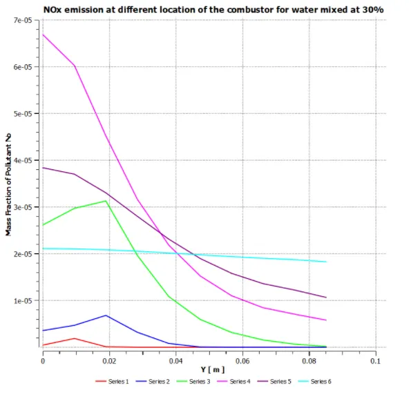
NOx contour and mass fraction chart
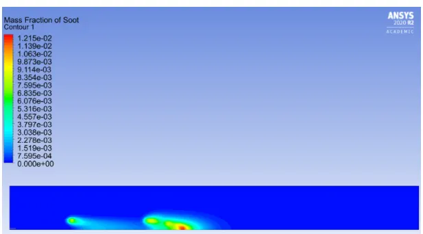
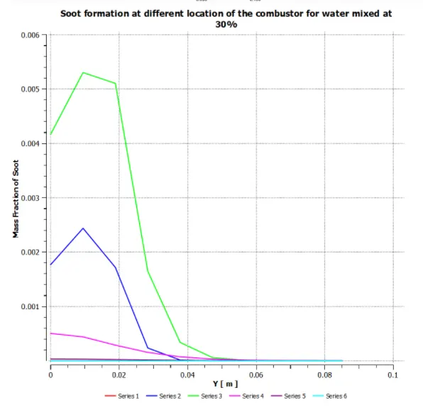
Soot contour and mass fraction chart
Conclusion:
Comparing NOX and soot levels for different water addiition levels :
% of water addition Ration of methane and water Mass fraction of NOx emissions Mass fraction of soot formations
10 0.9:0.1 2.68 e-4 4.01e-2
20 0.8:0.2 1.632 e-4 2.90 e-2
30 0.7:0.3 8.507 e-5 1.25 e-2
From above data, we can conclude below,
The concentrartion of NOx and soot formation is reduced with an increase in the mole fraction of water in the metahne-air mixture .With the addition of water in the fuel mixture , the temperature is reduced which in turn delays the combustion to take place which leads to an efficient mixing of air n fuel and with proper mixture of air and fuel complete combustion take place because of which nitrogen oxides formation is reduced as there is no oxygen left to react with oxygen left to react with nitrogen to form nitrogen oxides.
Soot is formed as a result of the burning of fuel in presence of less oxygen at low temperatures. As because of water addition, complte combustion takes place and hence efficient mixing of air and fuel takes place and there is less amount of air as well as fuel present after combustion as a result of soot formation is reduced.
With the increase in the mass fraction of water,
1. NOX pollutiojn is reduced,
2. Soot formation is reduced,
3. Efficient mixing of air and fuel is acheived,
4. Exhaust gas temperature is reduced .