Week 10: Project 1 - FULL HYDRO case set up (PFI)
Aim:
To simulate a full hydrodynamic simulation of a PFI Engine using CONVERGE.
Objectives:
- A brief introduction to the motion of the IC engine and its performance metrics
- Setting the full hydrodynamic case using CONVERGE Studio
- Calculating the performance parameters for the simulated PFI Engine
- Post processing the simulation results using Paraview
Theory:
The IC Engine is characterized by the 4 strokes of the piston which is translated using the crank shaft. The motion of the pistion from the bottom most to the top most position and vice versa is termed as the stroke of the pistion. The four strokes are classified as follows:
- Intake Stroke: The stroke initiates from the top dead center and terminates at the bottom dead center. The intake valve is open during this phase and the premixed mixture of the air and fuel enter in the combustion chamber because of the vaccum pressure created by the downward motion of the cylinder.
- Compression stroke: The stoke compresses the air-fuel mixture, by the upward motion of the pistion. Both valves of the intake and the exhaust are shut during this phase
- Combustion stroke: The compressed fuel air mixture is ignitied and this pushes the pistion to move from the top dead center to the bottom dead center thus providing power to the crank shaft. As a result, this stroke is called as the power stroke of the IC Engine. Both valves of the intake and the exhaust are shut during this phase
- Exhaust stroke: The crankshaft rotates the pistion from the bottom position to the top which pushes the combustion products of the fuel-air mixture out of the combustion chamber because the exhaust valve are open.
Compression ratio is defined as the ratio of the maximum volume of the cylinder when the piston as the bottom dead center and the minimum volume when the piston is at the top dead center.
The combustion efficiency of the engine is defined as the ratio between the energy released by the burnt fuel and the theoritical energy content of the fuel mass during one complete engine cycle.
ηbt=B.Pmf×C.V">ηbt=B.Pmf×C.Vηbt=B.Pmf×C.V
The combustion phase angles provide us the information about the proportion of the fuel that has been burned when the spark and the combustion has occured. For instance, the ca10, ca50, ca90 refer to the combustion phasing angle at which 10%, 50% and 90% of the fuel is consumed. These metrics are extremely important to calculate the start and the end of the combustion based on the spark angle.
The gross work of an engine is defined as the amount of the combustion energy converted to work. The torque of the engine is defined as rotational force generated by the crank shaft.
Wall heat transfer models are used because of the first cell size near the walls of the domain. As we have to perform the simulations in a feasible duration of the time, we have to use significantly coarse mesh and as a result cannot directly resolve the large temperature and velocity gradients. To mitigate this issue, we use wall heat transfer models and wall functions so that instead of providing boundary conditions to the wall we provide boundary conditon in the boundary layer of the fluid. This helps us to maintain some amount of accuracy in simultation but cutting the simulation time by order of magnitiude.
Geometry:
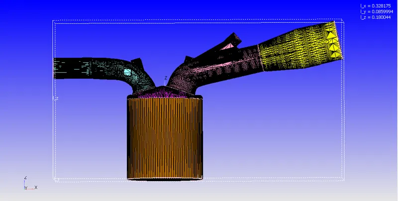
The geometry used for the current simulation study with appropriate boundary flagging and their dimensions in the direction of the Cartesian coordiantes is illustrated as follows:
Case Setup:
- Application Type:
- Since we are simualting a PFI engine, we choose a Crank Angle based IC Engine application
- The engine parameters are provided the following values: cylinder bore = 0.086 m, stroke = 0.09 m, connecting rod length = 0.18 m, Crank speed = 3000 RPM
- We set the references to the respective boundaries in the geometry
- Materials:
- We use the gas + parcel simualtion to model the air and the liquid fuel which is injected into the domain as parcels
- We choose the default parameters for the gas simulation and for the parcel simulation we choose the iso-octante (IC8H18) as the fuel for the current study. The thermodynamic and the physical properties of all the participating gaseous and parcel species is added using the custom therm.dat and mech.dat file
- The global transport parameters are set to default values
- Simulation Parameters:
- We use the tranisent, compressible solver for the flow of the gas while a transient, incompressible solver for the flow of the liquids. Both solvers temporal term type is set to Crank Angle based engine simulation and the simulation mode is chosen as fully hydrodynamic.
- The start angle of simulation is set to -500 degrees and the end time to 120 degrees so that an entire cycle of the IC Engine is simulated
- We choose the default density based PISO solver for solving the Navier Stokes equations.
- Boundary Conditions:
- Piston: Moving, translating wall and law of the wall at 450 K for the velocity and temperature boundary conditions and zero normal gradient for tke and wall model for eps
- Liner: Stationary, fixed wall and law of the wall at 450 K for the velocity and temperature boundary conditions and zero normal gradient for tke and wall model for eps
- Cylinder head: Stationary, fixed wall and law of the wall at 450 K for the velocity and temperature boundary conditions and zero normal gradient for tke and wall model for eps
- Spark plug: Stationary, fixed wall and law of the wall at 550 K for the velocity and temperature boundary conditions and zero normal gradient for tke and wall model for eps
- Spark plug terminal: Stationary, fixed wall and law of the wall at 600 K for the velocity and temperature boundary conditions and zero normal gradient for tke and wall model for eps
- Exhaust port: Stationary, fixed wall and law of the wall at 500 K for the velocity and temperature boundary conditions and zero normal gradient for tke and wall model for eps
- Outflow: Atmospheric Pressure of 1 bar and backflow temperature of 800 K and stochiometric combustion products as backflow species
- Exhaust valve top: Moving, translating wall and law of the wall at 525 K for the velocity and temperature boundary conditions and zero normal gradient for tke and wall model for eps
- Exhaust valve angle: Moving, translating wall and law of the wall at 525 K for the velocity and temperature boundary conditions and zero normal gradient for tke and wall model for eps
- Exhaust valve bottom: Moving, translating wall and law of the wall at 525 K for the velocity and temperature boundary conditions and zero normal gradient for tke and wall model for eps
- Intake port 1: Stationary, fixed wall and law of the wall at 425 K for the velocity and temperature boundary conditions and zero normal gradient for tke and wall model for eps
- Intake port 2: Stationary, fixed wall and law of the wall at 425 K for the velocity and temperature boundary conditions and zero normal gradient for tke and wall model for eps
- Inflow: Atmospheric Pressure of 1 bar and at temperature of 363 K with standard air as input species.
- Intake valve top: Moving, translating wall and law of the wall at 480 K for the velocity and temperature boundary conditions and zero normal gradient for tke and wall model for eps
- Intake valve angle: Moving, translating wall and law of the wall at 480 K for the velocity and temperature boundary conditions and zero normal gradient for tke and wall model for eps
- Intake valve bottom: Moving, translating wall and law of the wall at 480 K for the velocity and temperature boundary conditions and zero normal gradient for tke and wall model for eps
- Initial Conditions and Events:
- There are four regions: cylinder, exhaust port, intake port 1 and intake port 2
- The exhaust and cylinder regions are initialized with the exhaust products at a pressure of 1.85731 bar and 1360 K
- The intake port 1 which is closer to the combustion chamber is intialized with iso-octane fuel, oxygen and nitrogen at 1 bar and 390 K
- The intake port 2 is initialized with standard air at 1 bar and 370 K.
- Three events are set to connect the 4 regions. The 2 valve events connects the cylinder to the exhaust port and the intake port 1 respectively. the third permanent event connects the intake port 1 and the intake port 2 for the entire duration of the simulation.
- Physical Models:
- To model the iso-octane fuel parcel, we use the spray modelling feature. The following parameters were used to setup the fuel injection.
- Fuel flow rate= 7.5e-4 kg/s
- Injection start time= -480 degree
- Injection duration = 191.2 degree
- Fuel temperature = 330K
- The instabilty models such as the Kelvin-Helmholtz, Rayleigh-Taylor and Discharge model are used to model the cascade of the fluid parcels
- Four nozzles are used to inject the fuel into the intake port 1. The injection spray type is chosen as Solid Cone spary. The specifications of the four nozzles are as follows
- Nozzle 0: Diameter = 250 micrometers, Circular injection radius = Nozzle radius, spray cone angle = 10, center = 0.0823357 0.00100001 0.07019, align vector = -0.732501 0.210489 -0.647408
- Nozzle 1: Diameter = 250 micrometers, Circular injection radius = Nozzle radius, spray cone angle = 10, center = 0.0823357 -0.00099999 0.07019, align vector = -0.732501 -0.210489 -0.647408
- Nozzle 1: Diameter = 250 micrometers, Circular injection radius = Nozzle radius, spray cone angle = 10, center 0.0823357 -0.0004 0.07019, align vector = -0.5 -0.2 -0.647408
- Nozzle 3: Diameter = 250 micrometers, Circular injection radius = Nozzle radius, spray cone angle = 10, center =
- 0.0823357 0.0003 0.07019, align vector = -0.5 0.2 -0.647408
- The spark ignition is modelled by providing two spherical sources in the vicinity of the spark plug terminal, such that the real experimental profile is approximately modelled in form of two constant sources, such that the total heat released is same. The source 1 starts at -15 and ends at -14.5 with an energy of 20 mJ and the source 2 starts from -15 to -5 degree with the energy of 20 mJ
- The combustion is modelled using the default SAGE detaield chemistry solver. The combustion modelling begins just before the spark ignition form -17 and completes as soon as the exhaust valve opens at 130 degrees. Combustion temperature cutoff is set to 600 K and minimum hydrocarbon species mole fraction for combustion to take place is set to 10-8">10−810-8
- For the turbulence modelling, we choose the RNG k-eps model and the near wall treatment is done using the Standard wall functions and the wall heat transfer model is set to O'Rourke and Amsden with default values
- To model the iso-octane fuel parcel, we use the spray modelling feature. The following parameters were used to setup the fuel injection.
- Grid Control:
- We have a base grid of 4 mm in all principal directions
- Adaptive Mesh refinement in the intake port 1, intake port 2 and cylinder region is done so that the physical and chemical interactions between the air and the fuel and the combustion in these regions are captured accurately. The embedding based on velocity is set to permanent while the embedding based on the temperature is kept cyclic between the start and the end of the combustion
- To accuractely capture the flow and combustion physics and its gradients near the valves, injector and the entire cylinder region during combustion and the valves opening time, we give fixed embbedding so that the adapative mesh refinement works as expected.
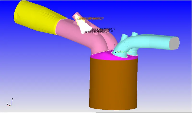
The figure of the geometry after the case setup is complete is as follows. We can clearly observe the injection nozzles and the source terms which models the ignition.
Observations & Calculations:
The animation of the fuel parcels in the combustion chamber is available:
https://drive.google.com/file/d/1044avpuSovJGR5_oIsQ3imFAknv27yCB/view?usp=sharing
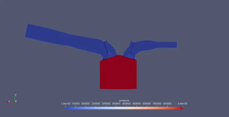
The contours and the plots of the simulation are as follows:
Temperature Contours:
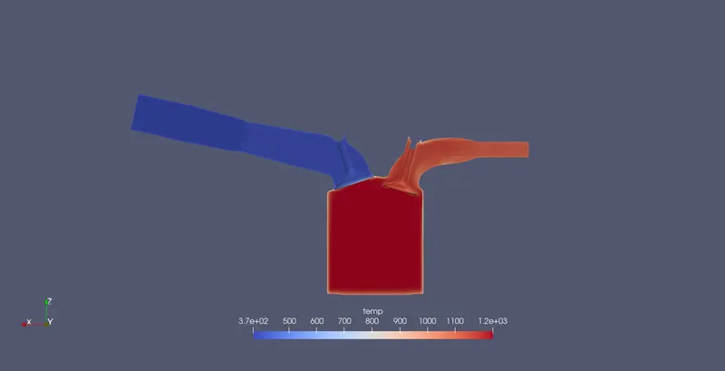
Temperature Contour @ Crank angle = -500
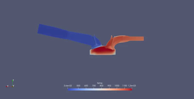
Temperature Contour @ Crank angle = -400
Temperature Contour @ Crank angle = -300
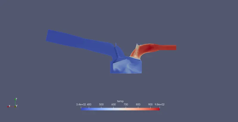
Temperature Contour @ Crank angle = -200
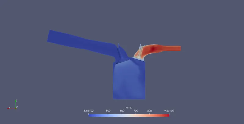
Temperature Contour @ Crank angle = -150
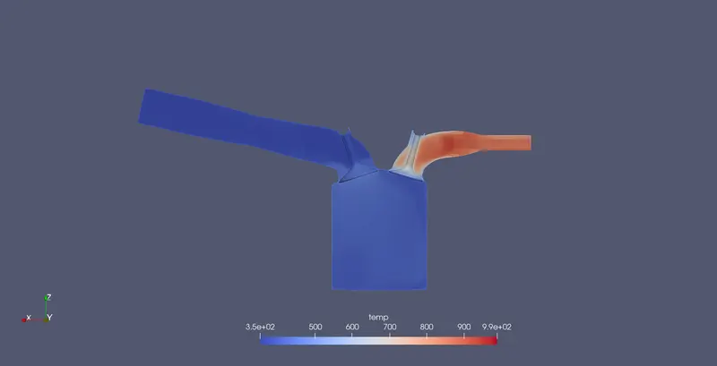
Temperature Contour @ Crank angle = -100
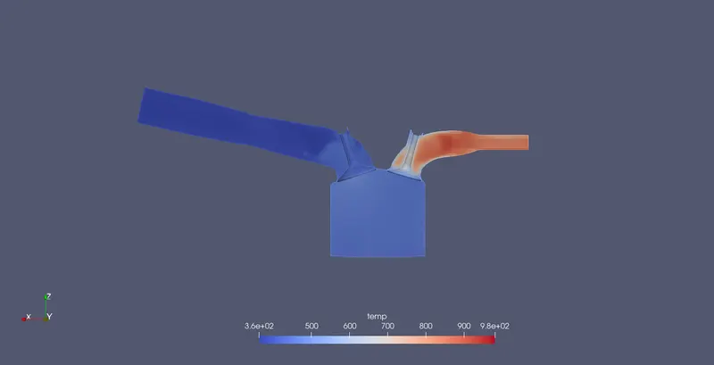
Temperature Contour @ Crank angle = 0
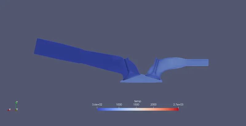
Temperature Contour @ Crank angle = 100
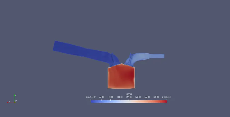
Pressure Contours:
Pressure Contour @ Crank angle = -500
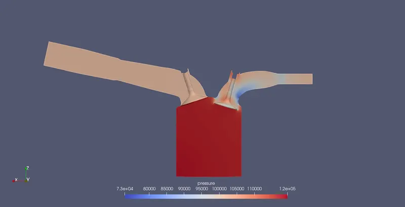
Pressure Contour @ Crank angle = -400
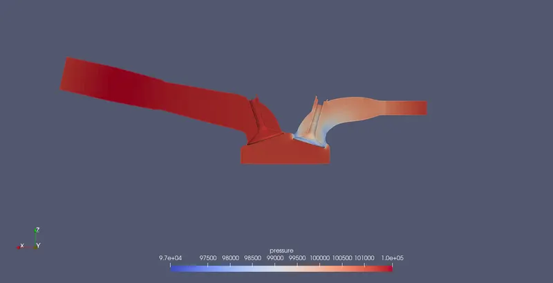
Pressure Contour @ Crank angle = -300
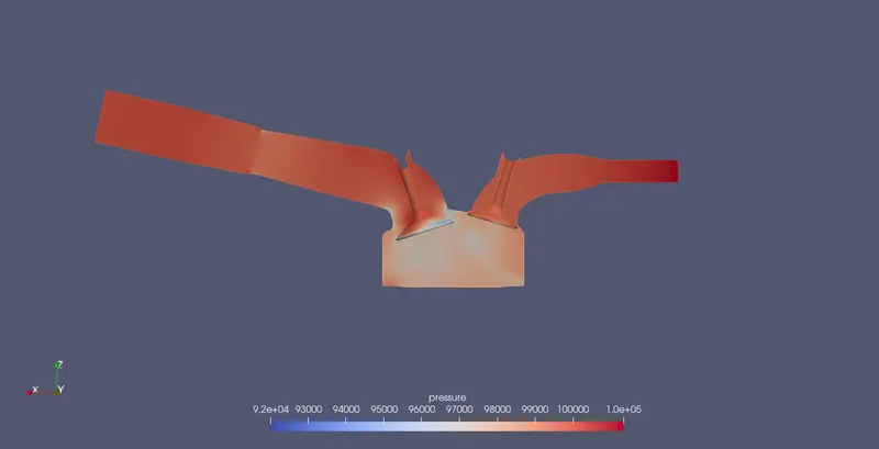
Pressure Contour @ Crank angle = -200
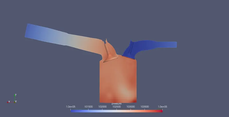
Pressure Contour @ Crank angle = -150
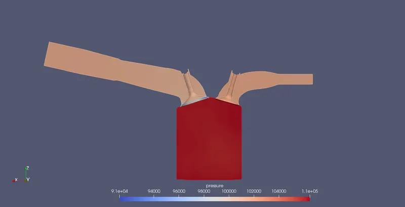
Pressure Contour @ Crank angle = -100
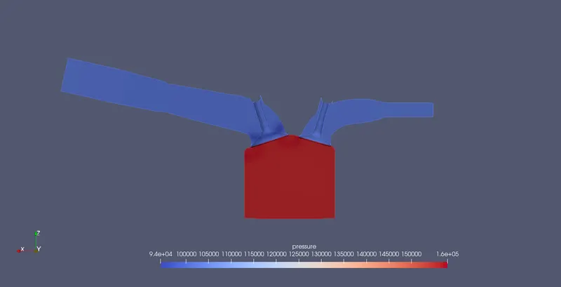
Pressure Contour @ Crank angle = 0
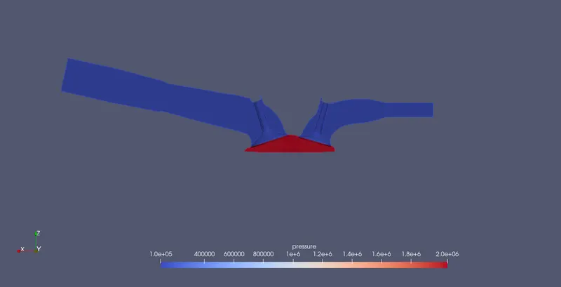
Pressure Contour @ Crank angle = 100
Velocity Contours:
Velocity Contour @ Crank angle = -500
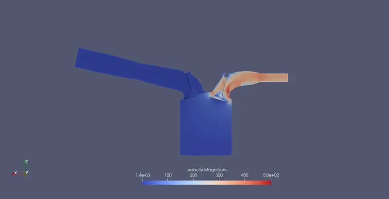
Velocity Contour @ Crank angle = -400
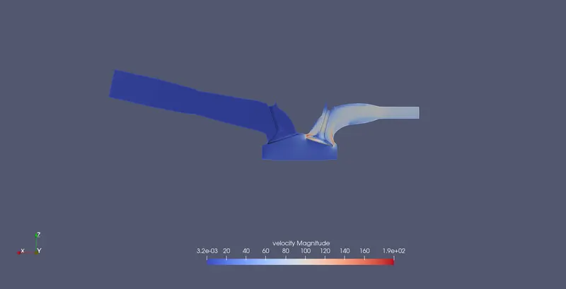
Velocity Contour @ Crank angle = -300
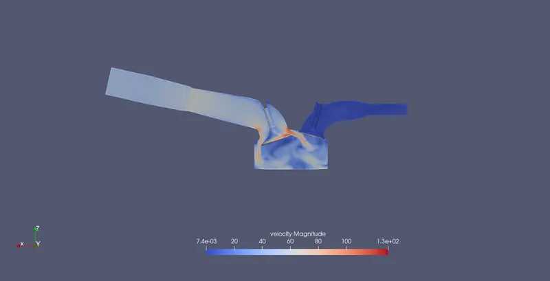
Velocity Contour @ Crank angle = -200
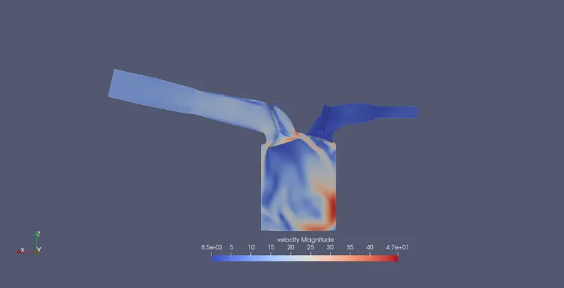
Velocity Contour @ Crank angle = -150
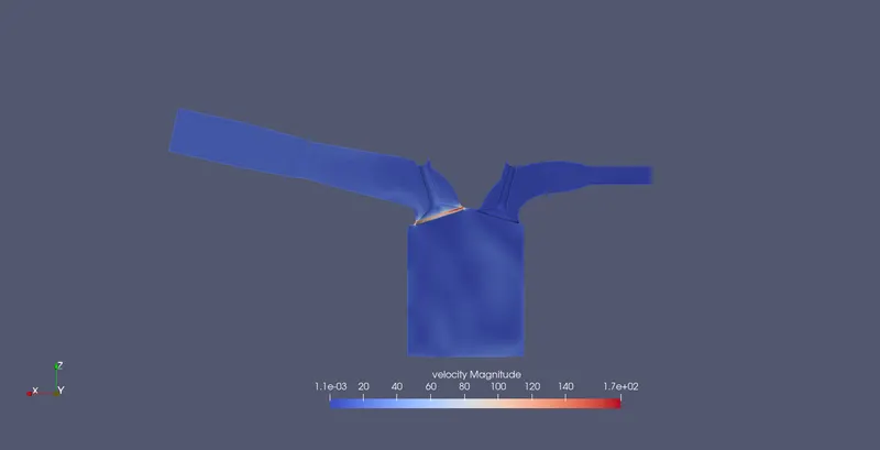
Velocity Contour @ Crank angle = -100
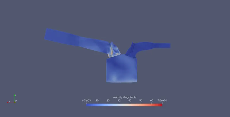
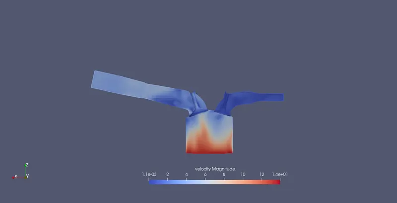
Velocity Contour @ Crank angle = 0
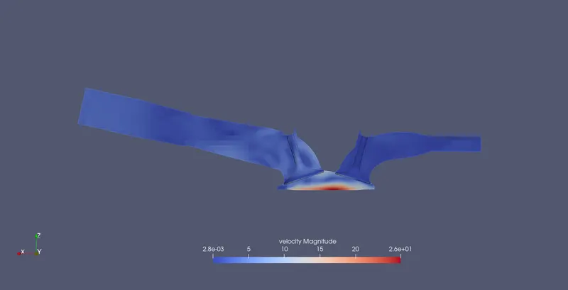
Velocity Contour @ Crank angle = 100
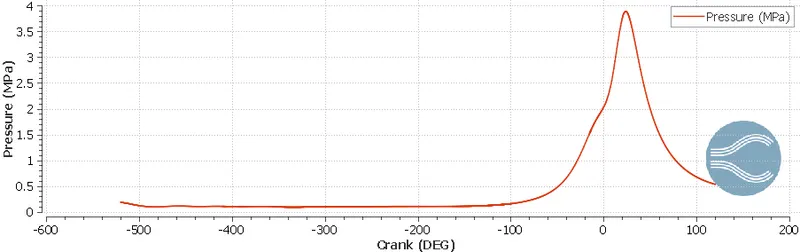
Pressure variation inside the cyliner with respect to crank angle
Volume variation inside the cylinder with respect to crank angle
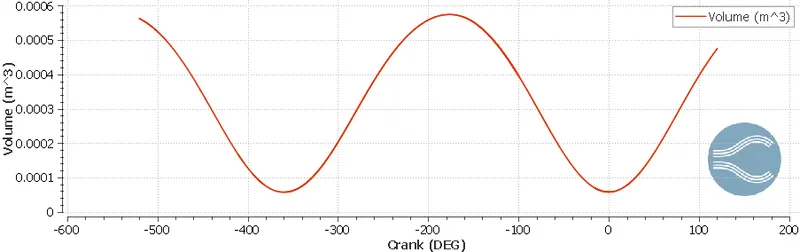
The compression ratio is defined as the ratio of the volume of the combustion chamber when it is at the bottom dead center and the volume of the combustion chamber when it is at the top dead center. Mathematically, it can be represent as,
Compressionratio=VolB.D.CVolT.D.C">Compressionratio=VolB.D.CVolT.D.CCompressionratio=VolB.D.CVolT.D.C
From the above graphs, we can extract the maximum volume and the minimum volume and find the compression ratio.
Compressionratio=9.98">Compressionratio=9.98Compressionratio=9.98
Temperature variation inside the cylinder with respect to crank angle
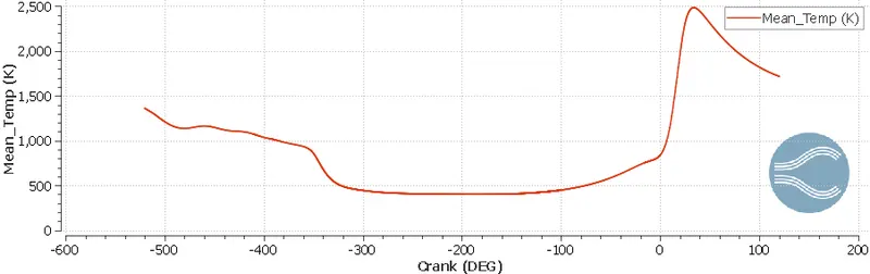
Heat Release rate variation inside the cylinder with respect to crank angle
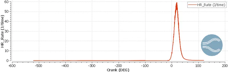
Integrated heat release rate variation inside the cylinder with respect to crank angle
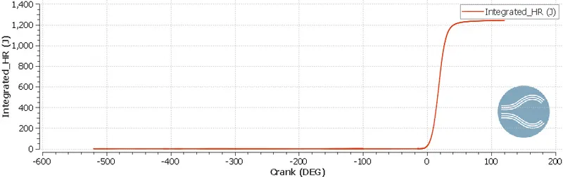
To calculate the combustion efficiency, we observe the intergrated heat release after the combustion stroke is over and then normalize this value with the amount of the energy inputed in the system. We represent the combustion efficieny as ηc">ηcηc.
Mathematically, we represent the formula for combustion efficiency as,
ηc=I.H.Rmf×C.V">ηc=I.H.Rmf×C.Vηc=I.H.Rmf×C.V
From our results = I.H.R=1241.1646J">I.H.R=1241.1646JI.H.R=1241.1646J, mf=3×10⁻⁵kg">mf=3×10⁻⁵kgmf=3×10⁻⁵kg, Cv=44000kJkg">Cv=44000kJkgCv=44000kJkg. Substituting these values in the in the above equation we get,
ηc=0.9403">ηc=0.9403ηc=0.9403.
Hence, the combustion efficiency of the PFI engine is 94.03%.
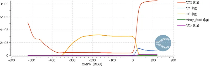
Emissions generated inside the cylinder with respect to crank angle
Performance parameters of the PFI Engine
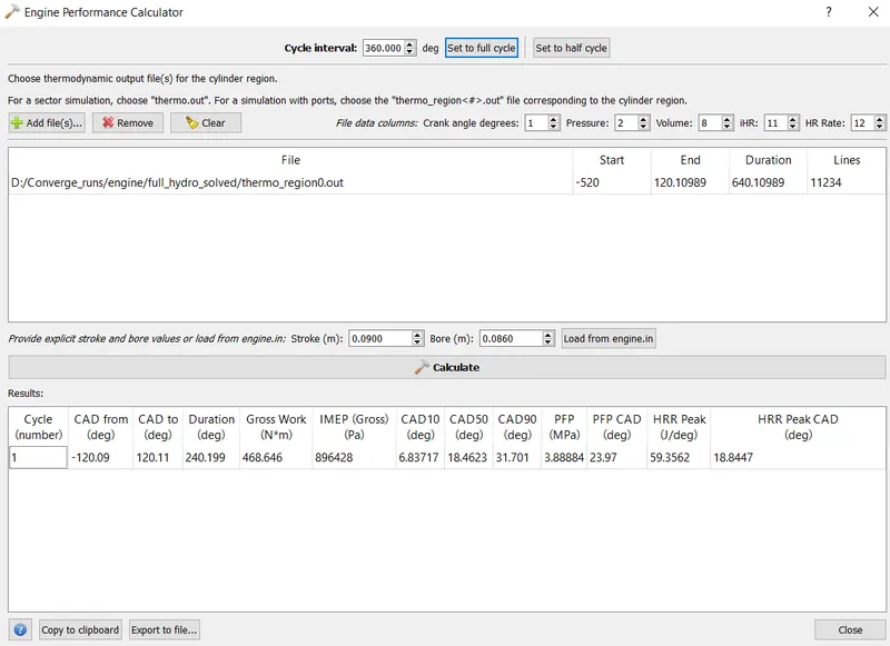
From the above performance metrics, we can calculate the power generated by the engine.
Mathematically power is represented the rate of work done per unit time,
P=dWdt">P=dWdtP=dWdt
From the starting and ending angles of the combustion, we can calculate the duration of the time for which ignition took place for an engine working at 3000 RPM.
t=240.2×60360×3000=0.01334s">t=240.2×60360×3000=0.01334st=240.2×60360×3000=0.01334s
Therefore, power is equal to
P=Wt=486.6460.01334=35.13kW">P=Wt=486.6460.01334=35.13kWP=Wt=486.6460.01334=35.13kW
The torque (T) and the power (P) are connected by the following formula
T=60×P2π×N">T=60×P2π×NT=60×P2π×N
Substituting all the known values, we get the value of torque as
T=111.879Nm">T=111.879NmT=111.879Nm
Conclusions:
We have successfully performed a full hydrodynamic simulation of PFI Engine which has generated over ~300 GBs of data for post processing. The combustion efficiency of this engine is 94.03 %. The power and the torque generated by the engine is 35.13 kW and 111.879 Nm respectively. From the emissions we can conclude that the relatively high amount of CO compared to other emission gases is due to incomplete combustion.