Simulation of PFI (Port fuel injection) engine using Converge
Aim: To set up and perform Fullhydro simulation of PFI (Port fuel injection) engine using Converge.
Objective:
- Set up full hydro simulation using Converge Studio.
- Obtain the compression ratio of the given engine.
- Calculate the combustion efficiency of the engine.
- Use the engine performance calculator, to determine the power and torque for this engine.
PFI engine
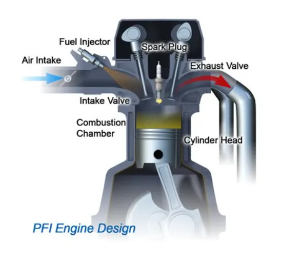
In PFI engines the fuel is sprayed into the intake ports to mix with incoming air. The fuel injectors in PFI configurations are typically mounted in the intake manifold and the air/fuel mixture is pulled into the cylinder head as the intake valve opens.
Geometry
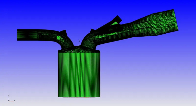
Import the STL file in converge studio and perform surface preparation. After removing all the surface errors, flag the boundaries.
Case setup
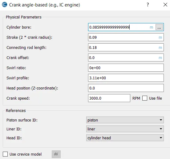
Application type: Crank angle based
Engine parameters
Material
'mech.dat' file is imported to the reaction mechanism. Gas thermodynamic data is given as a 'therm.dat' file. For the parcel simulation, parcel liquid and species are defined as the fuel. In this case IC8H18.
Simulation parameters
Solver: Transient
Simulation mode: Full hydrodynamic
Gas flow solver: Compressible
Liquid flow solver: Incompressible
Navier Stokes solver scheme: PISO
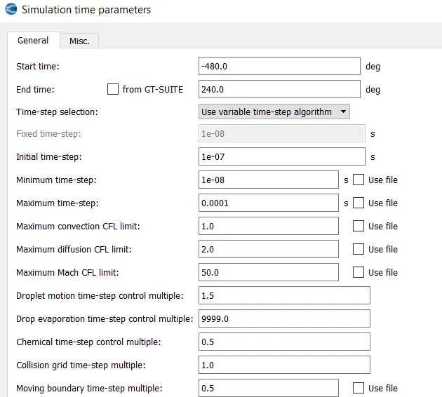
Simulation time parameters
Regions and initial conditions
| Region | Pressure(Pa) | Temperature(K) | Species |
| Cylinder region | 101325 | 300 | CO2(0.192304),H2O(0.088559),N2(0.719137) |
| Intake port 1 | 101325 | 390 | IC8H18(0.025508),N2(0.77292),O2(0.20157) |
| Intake port 2 | 101325 | 370 | O2(0.23),N2(0.77) |
| Exhaust port | 185731 | 1360 | CO2(0.192304),H2O(0.088559),N2(0.719137) |
Events
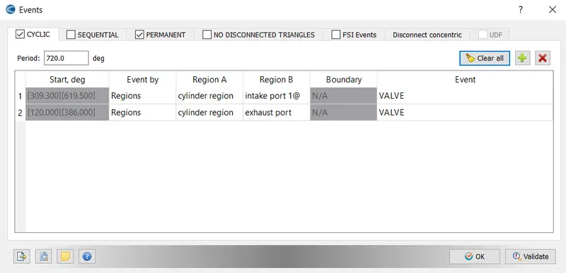
For this simulation 2 cyclic events were created for connecting the intake port and exhaust port to the cylinder region. The event is a valve type. Valve profile is taken from boundary conditions. A permanent event is also created for connecting intake port 1 and intake port 2 regions.
Boundary conditions
| Boundary | Boundary type | Wall motion type | Temperature (K) | Pressure (Pa) | Region |
| Inflow | Inflow | _ | 363 | 101325 | Intake port 2 |
| Intake port 1 | Wall | Stationary | 425 | _ | Intake port 1 |
| Intake port 2 | Wall | Stationary | 425 | _ | Intake port 2 |
| Intake valve top | Wall | Translating | 480 | _ | Intake port 1 |
| Intake valve angle | Wall | Translating | 480 | _ | Intake port 1 |
| Intake valve bottom | Wall | Translating | 480 | _ | Cylinder region |
| Cylinder head | Wall | Stationary | 450 | _ | Cylinder region |
| Spark plug | Wall | Stationary | 550 | _ | Cylinder region |
| Spark plug terminal | Wall | Stationary | 600 | _ | Cylinder region |
| Liner | Wall | Stationary | 450 | _ | Cylinder region |
| Piston | Wall | Translating | 450 | _ | Cylinder region |
| Exhaust valve top | Wall | Translating | 525 | _ | Exhaust port |
| Exhaust valve angle | Wall | Translating | 525 | _ | Exhaust port |
| Exhaust Valve bottom | Wall | Translating | 525 | _ | Cylinder region |
| Exhaust port | Wall | Stationary | 500 | _ | Exhaust port |
| Outflow | Outflow | _ | 800 | 101325 | Exhaust port |
Wall motion profile for intake valve and exhaust valve are given as files 'intake_lift.in' and 'exhaust_lift.in'. The motion of the piston is defined as piston motion.
Grid control
Base grid size=0.004m
Adaptive mesh refinement (AMR)
AMR refine the mesh when the gradient of a parameter is higher than a particular value (Sub grid-scale value). In this case, AMR is given on cylinder, intake port1, and intake port2 regions. AMR is created for temperature and velocity with SGS 2.5 and 1 respectively. The maximum embedding level for both the AMR is 3.
Base grid size=4mm
Maximum embedding level = 3
Minimum cell size= `4/(2^3)=0.5 mm`
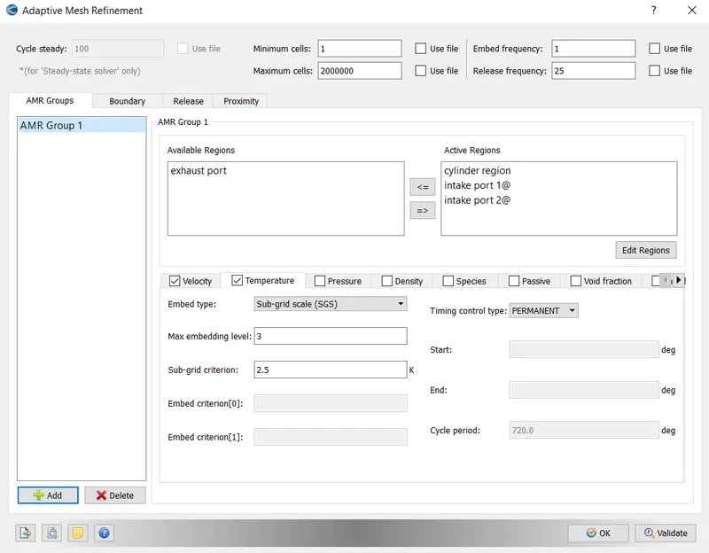
Also, a fixed embedding is created for intake valve angle and exhaust valve angle to avoid cell pairing. In order to capture the cylinder region a region-based embedding is given to it. A cyclic embedding is given to the injector also.
Physical models
Spray modeling
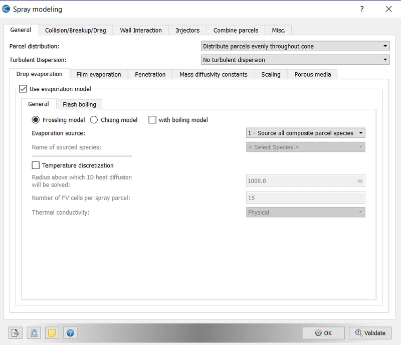
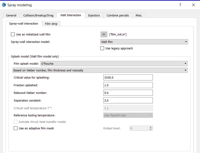
Spray modeling is used for simulating fuel injection. For gaseous spray, CONVERGE uses an Eulerian solver, and for liquid spray, CONVERGE uses a Lagrangian solver to model discrete parcels and an Eulerian solver to model continuous fluid domain.
The different parameters selected are shown below,
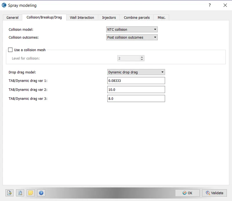
We need to set up an injector and nozzles. In this case, we use a single injector with 4 nozzles.
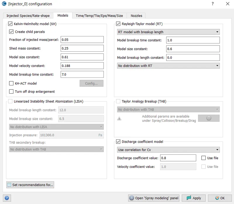
Nozzle diameter = 250 micro-meter
Circular injection radius = Nozzle radius
Spray cone angle = 10
- Nozzle 0
- center 0.0823357 0.00100001 0.07019
- Align Vector -0.732501 0.210489 -0.647408
- Nozzle 1
- center 0.0823357 -0.00099999 0.07019
- Align Vector -0.732501 -0.210489 -0.647408
- Nozzle 2
- center 0.0823357 -0.0004 0.07019
- Align Vector -0.5 -0.2 -0.647408
- Nozzle 3
- center 0.0823357 0.0003 0.07019
- Align Vector -0.5 0.2 -0.647408
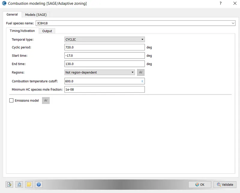
Combustion modeling
For capturing the combustion of fuel combustion modeling is used. In this simulation, the SAGE model is used with fuel as IC18H18.
Turbulence model
RNG K epsilon
Result
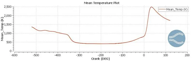
Temperature change inside the combustion chamber
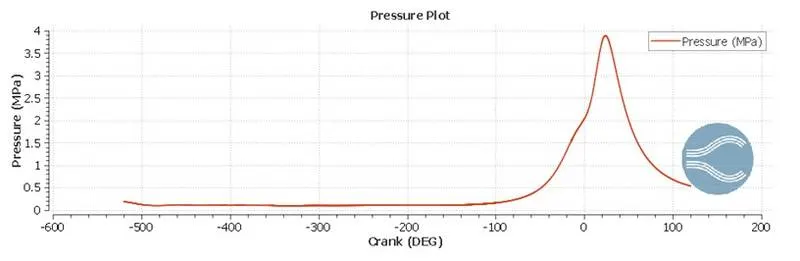
Pressure change inside the combustion chamber
Emission
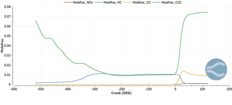
The mole fraction of exhaust products is shown in the plot above.
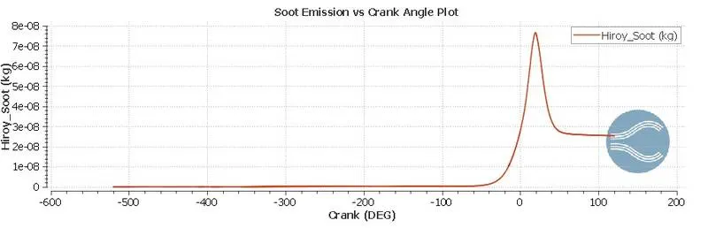
Soot emission
Total cells
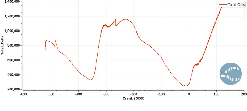
Since AMR is added the number of cells increases when the gradient is higher than the SGS value.
Compression ratio
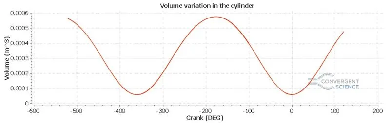
Cylinder volume vs crank plot
Compression ratio=`(V_d+V_c)/V_c`
 = displacement volume
 = clearance volume
Minimum volume of the cylinder=0.00005 m3
Maximum volume of the cylinder=0.00055 m3
Compression ratio=`0.00055/0.00005`=11
Combustion efficiency
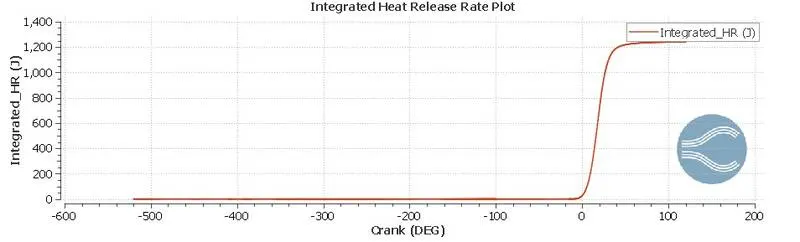
Peak integrated heat release rate=1240 J
Combustion efficency=(Total energy released/Energy content of fuel per cycle)*100
Mass of fuel=3e-5 Kg
LHV of fuel=43.44 MJ
Energy content of fuel per cycle= 3e-5*43.44 MJ =1303.2 J
Combustion efficency=(1240/1303.2)*100= 95.15 %
Power and torque
Work done=468.86
Combustion duration= 240 deg
Crank speed =3000 rpm= 50 RPS
Degrees per second= 18000
Time=240/18000=0.0133 s
Power= work done / Time= 468.86/0.0133=35252.6 W
Power(P) = (2*π*N*T)/60
Hence torque `T=(P*60)/(2 piN)`
T=`(35252.6*60)/(2*pi*3000`=112.21 N-m
Animation
Piston and valve motion
Flame propagation
Conclusion
The simulation of the PFI engine is performed and plotted different parameters and calculated engine performance.