Week 10: Project 1 - FULL HYDRO case set up (PFI)
Aim: Full-scale simulation of port fuel ignition (SI8)
Note: Please refer to the No- Hydro case for more information about the case setup .
In this project spray modelling and postprocessing, results are discussed.
Spray Modelling:
Injection Parameters
Fuel flow rate :7.5e-4 kg/s
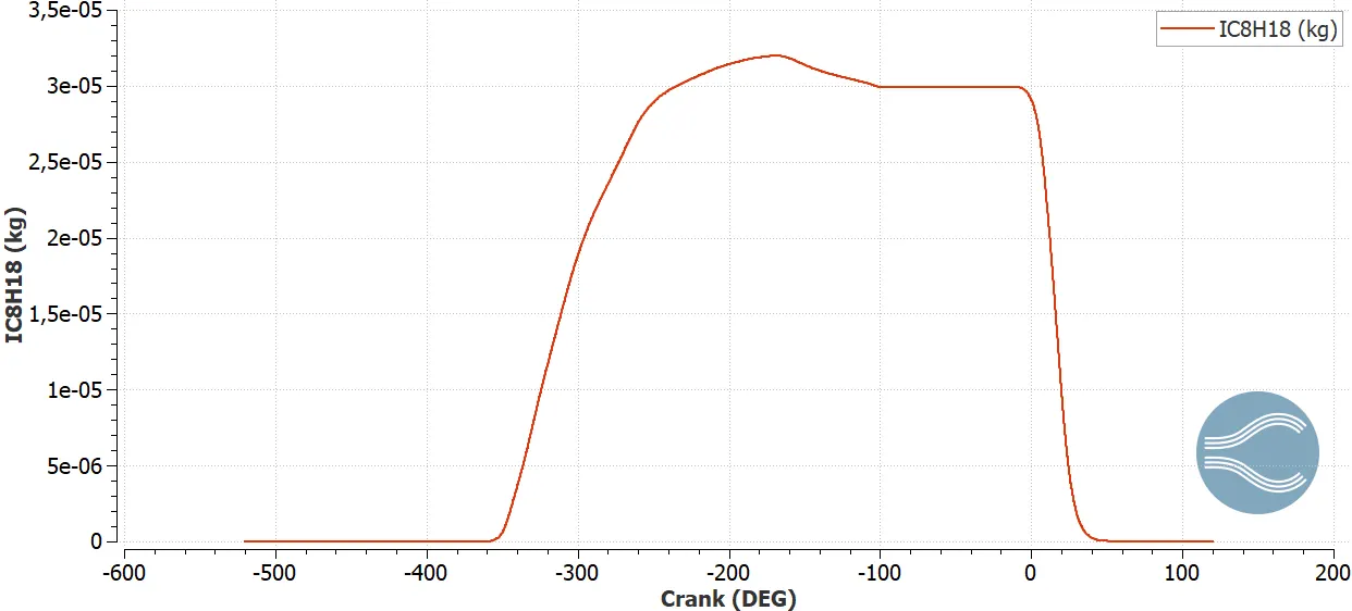
Since for every 720 degree fuel is being injected with a rpm of 3000 -> Total mas per cycle results in 3e-5 kg=30 mg
Injection timing: -480 degree
Injection duration :191.2 degree
Fuel species : IC8H8
Fuel temperature : 330 K
Nozzle Parameters :
Nozzle diameter :250 `mu`m
Circular Injection Radius : 125 `mu`m
- Nozzle 0
- center 0.0823357 0.00100001 0.07019
- Align Vector -0.732501 0.210489 -0.647408
- Nozzle 1
- center 0.0823357 -0.00099999 0.07019
- Align Vector -0.732501 -0.210489 -0.647408
- Nozzle 2
- center 0.0823357 -0.0004 0.07019
- Align Vector -0.5 -0.2 -0.647408
- Nozzle 3
- center 0.0823357 0.0003 0.07019
- Align Vector -0.5 0.2 -0.647408
Source/Sink Modelling:
Spark Ignition parameters
Start of spark : -15 degrees
Duration of spark :10 degrees
spark location :[-0.003 0, 0.00915]
spark radius : 0.0005 m
Energy Source for spark
Source Shape:Sphere
Source Mode :Cyclic
Period:720 degrees
For source 0,
energy :0.02 J
start time :-15 degrees
End time : -14.5 degrees
For source 1,
energy :0.02 J
start time :-15 degrees
End time : -5 degrees
Combustion Modelling :
Fuel Species:IC8H8
Temporal Type:Cyclic
start time : -17 degrees
end time : 130 degrees
Combustion model: SAGE
Pressure plot :
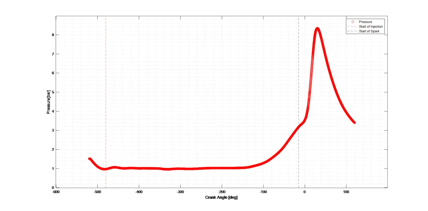
Above plot depicts the pressure rise in the cylinder. At -15 before TDC spark is initiated and there after combustion proceeds and which leads to rise in the pressure .
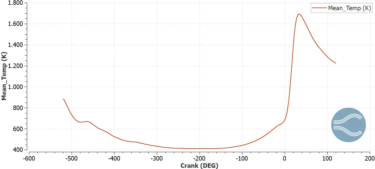
Mean Temperature:
IC8H8 - Fuel mass
Heat wall transfer Model :
Wall Heat transfer model is essential because it also influences the overall efficiency of the engine. In this simulation, only the fluid domain is modelled and wall heat transfer is not considered. Hence it's not possible to compute the wall temperatures due to the absence of the physical properties of the wall. However, modelling wall heat transfer will result in increased simulation time. The idea is to focus on the objective of the research and accordingly investigations are made else it would be computational very expensive .
Volume (m^3)
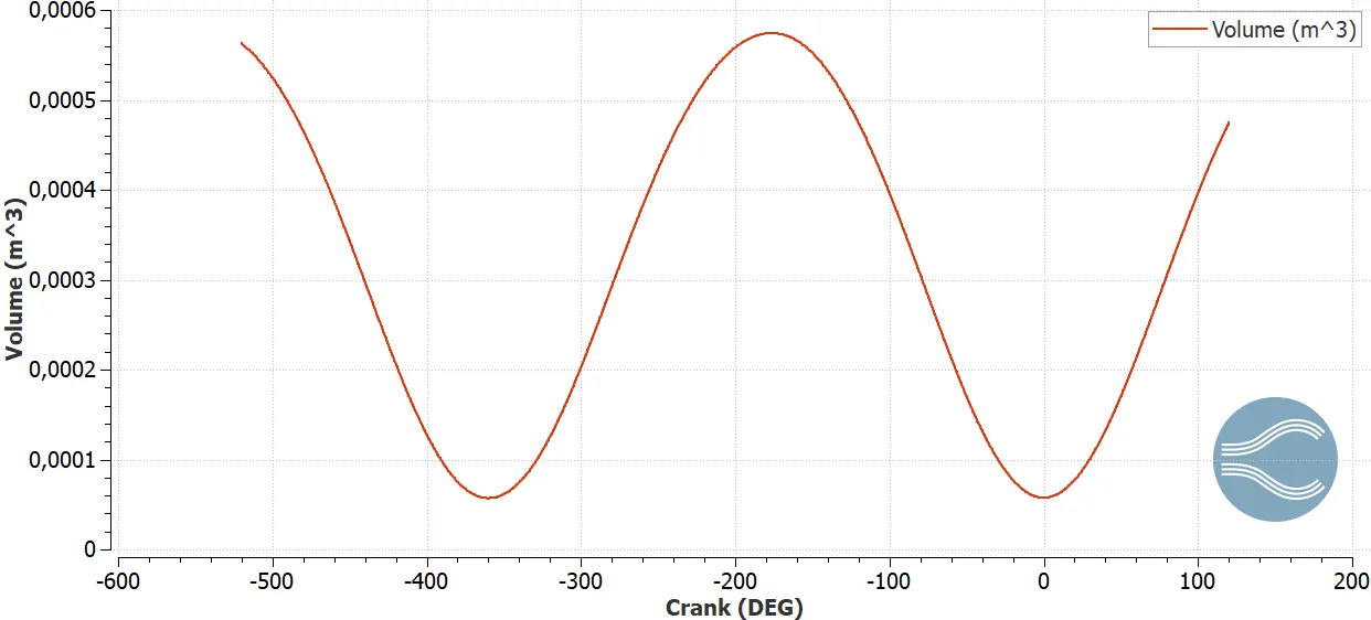
Minimum Volume(trough) : 5.70298e-5
Max Volume(crest) : 0.000574218
Compression ratio : Max Volume/Minimum Volume=10.06
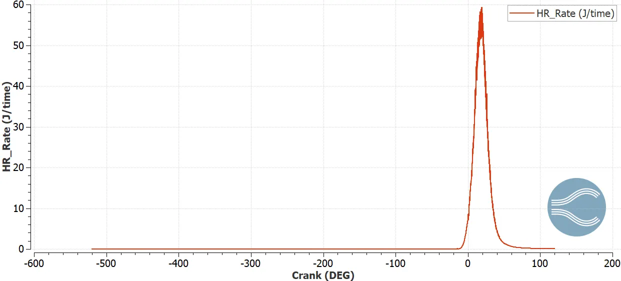
Heat Release rate :
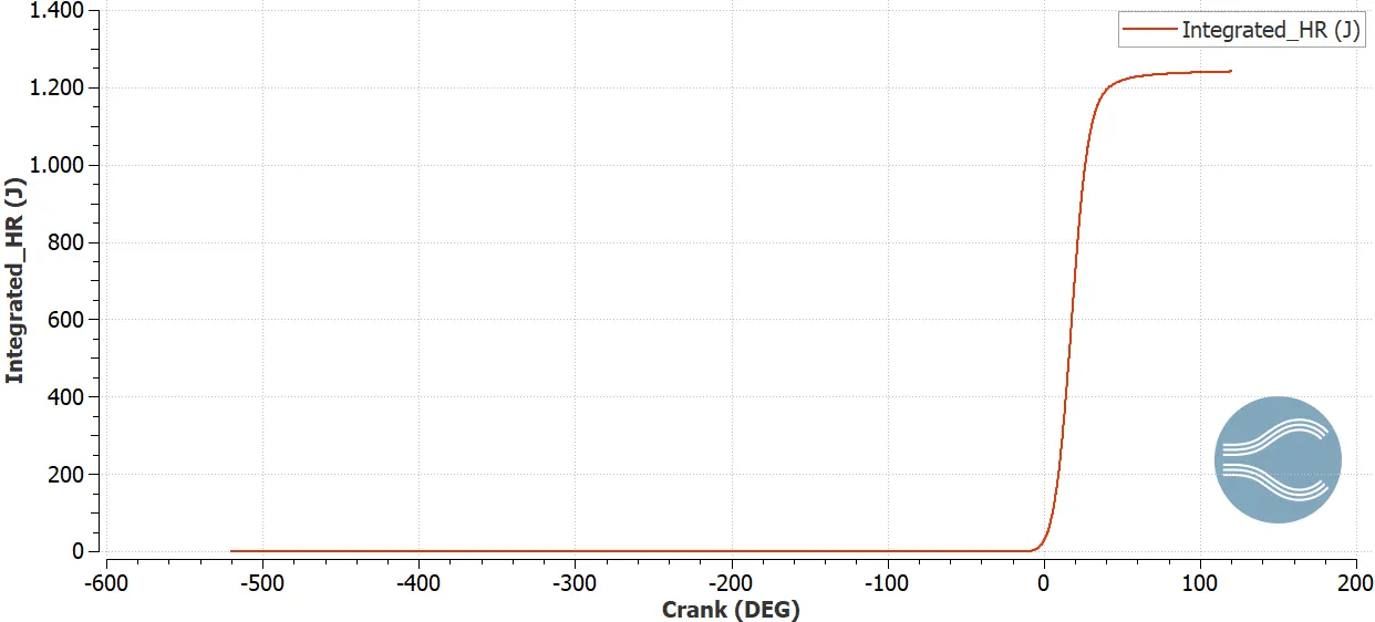
Integrated Heat Release Rate
HRR
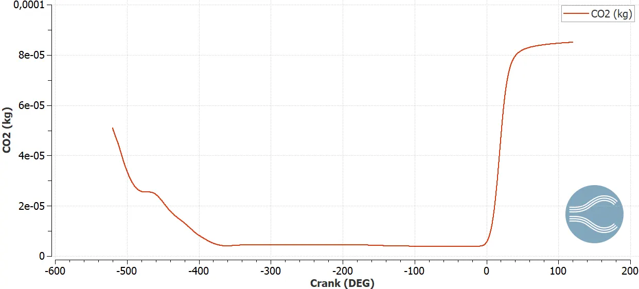
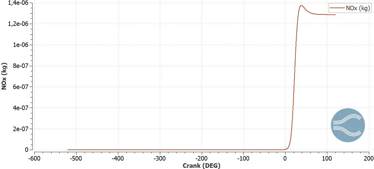
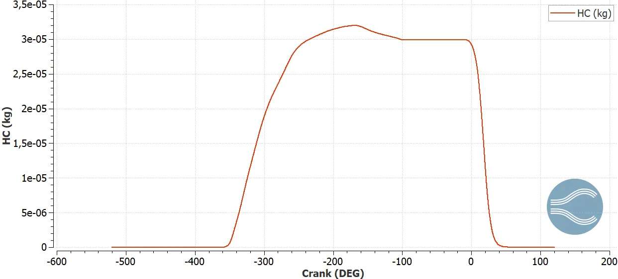
Emissions:
CO2
Nox
HC
Performance parameters:
Efficiencies can be computed using the rate of heat release
Int_HRR = 1241.14 J % Total heat release from above plot
Total Mass of fuel = 3e-5 kg = 30mg
LHV = 44 Mj/kg
Qin = Total mas of fuel * LHV
Combustion efficiency = Int_HRR/44e6 =1241.14 /Qin =94.03 %
Work :468.646 N-m
Power
Speed: 3000 rpm
RPS = Speed/60 = 50
Degrees per second = 50 * 360 =18000
Time of combustion :Combustion Duration/ Degrees per second=0.0133 sec
Power : Work /Time of combustion =468.646/0.0133=35236.54 Watt
We know
P= 2*pi*N*T/60
Re-arranging the above equation
T=60*P/2*pi*N= 2*35236.54/(2*3.142*3000)=112.16 N-m
Engine Performance Tool :
:
Significance of CA10, CA50 and CA90 :
CA10 CA50 and CA90 represent the crank angles at which the 10,50 and 90 % of the fuel is burned respectively. Most of the engine researcher focuses on the CA50, where 50 % of the fuel is burned. These basically start, mid and endpoint where combustion takes place.