PORT FUEL INJECTION SIMULATION (Converge Studio)
AIM:
Full Hydro simulation of Port Fuel Injection.
OBJECTIVE:
To simulation full hydro transient simulation of PFI engine
Suface preparation and Boundary Flagging.
To calulate:
Compression Ratio.
Combustion Efficiency.
Power and Torque
Significance of CA10,CA50,CA90
GEOMETRY:
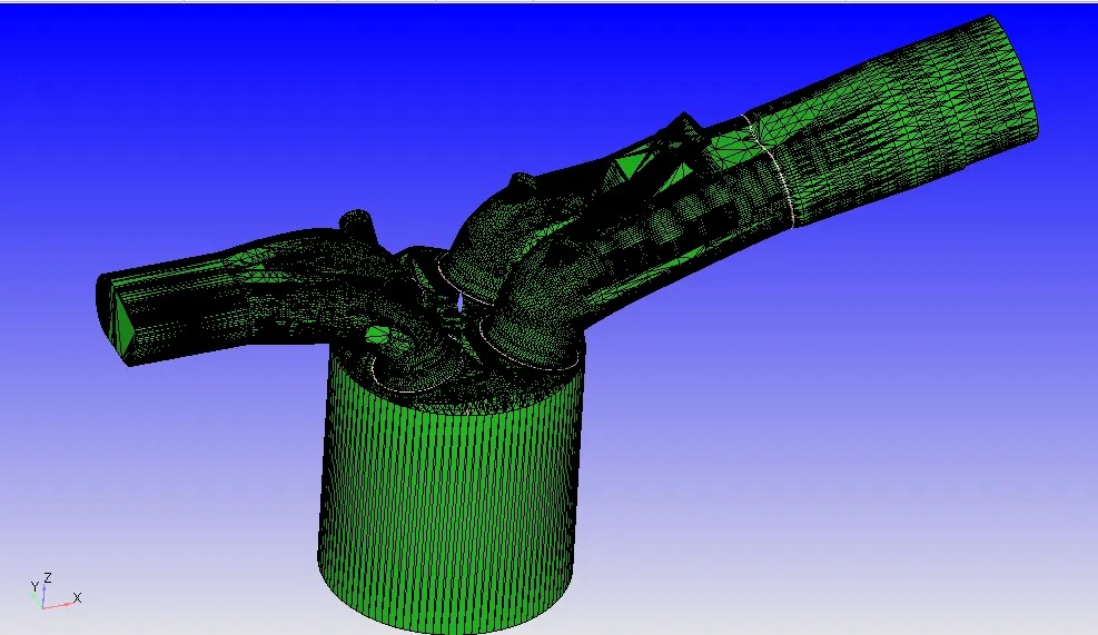
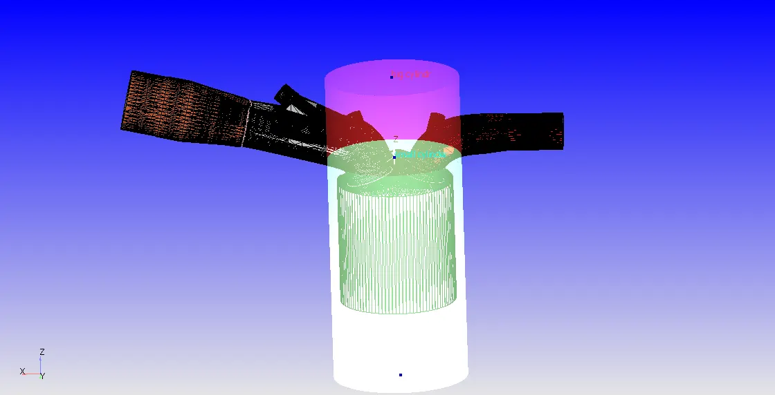
PFI geometry is imported as an Stl file. This is a base geometry have lot of errors for this errors surface preparation and boundary flagging is done along with the case setup.
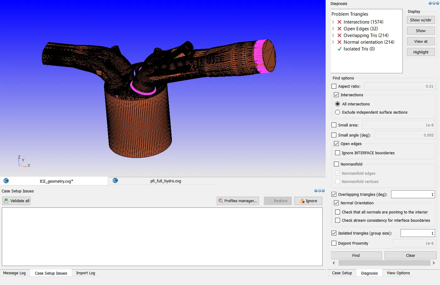
Diagnosis:
By doing Diagnosis ther is a lot of error in the geometry to simulation the case this error should be fixed.
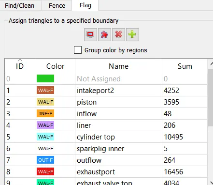
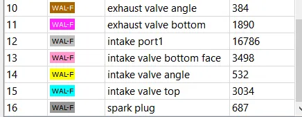
BOUNDARY FLAGGING:
SURFACE PREPARATION:
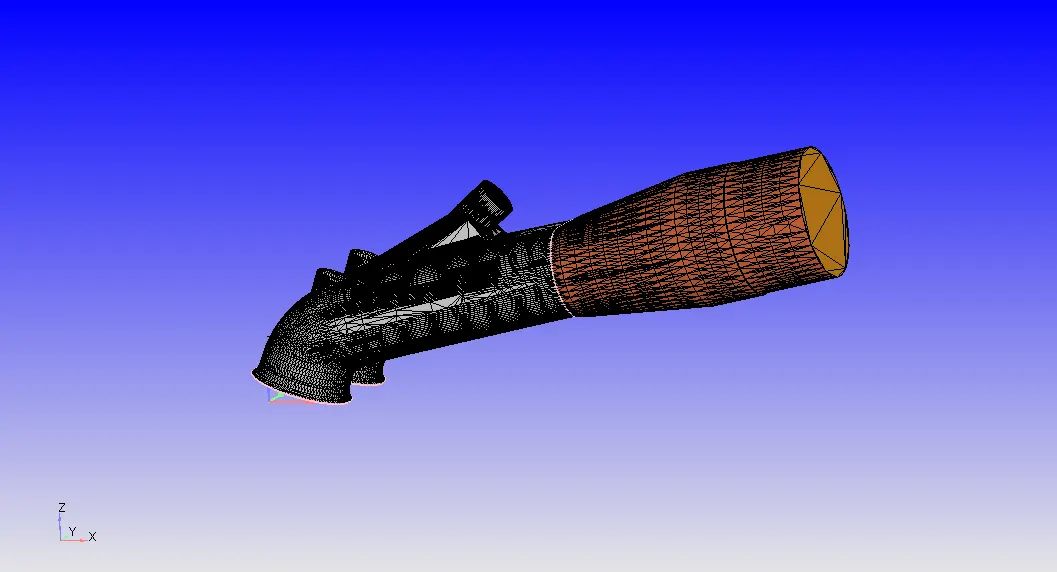
Intake ports:
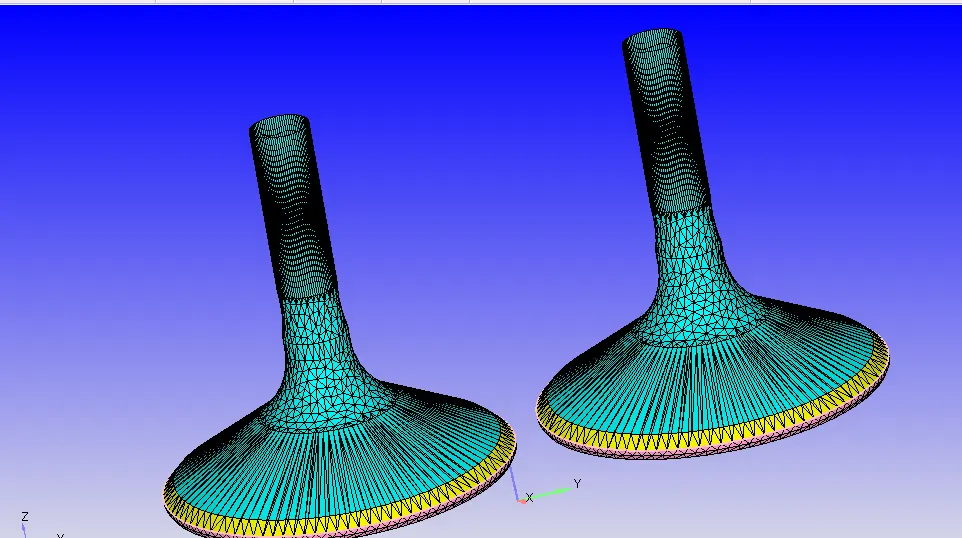
Intake valves, angles and bottom:
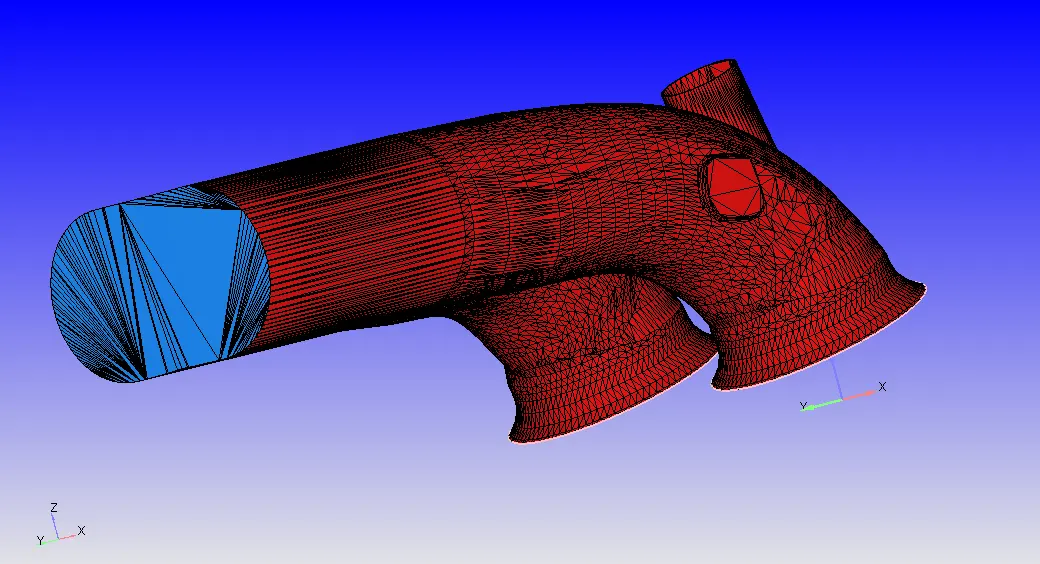
Exhaust ports:
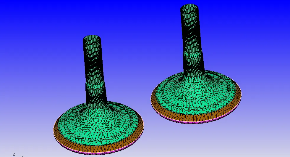
Exhaust valves, angles and bottom:
Liner and Piston:
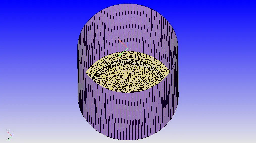
Cylinder:
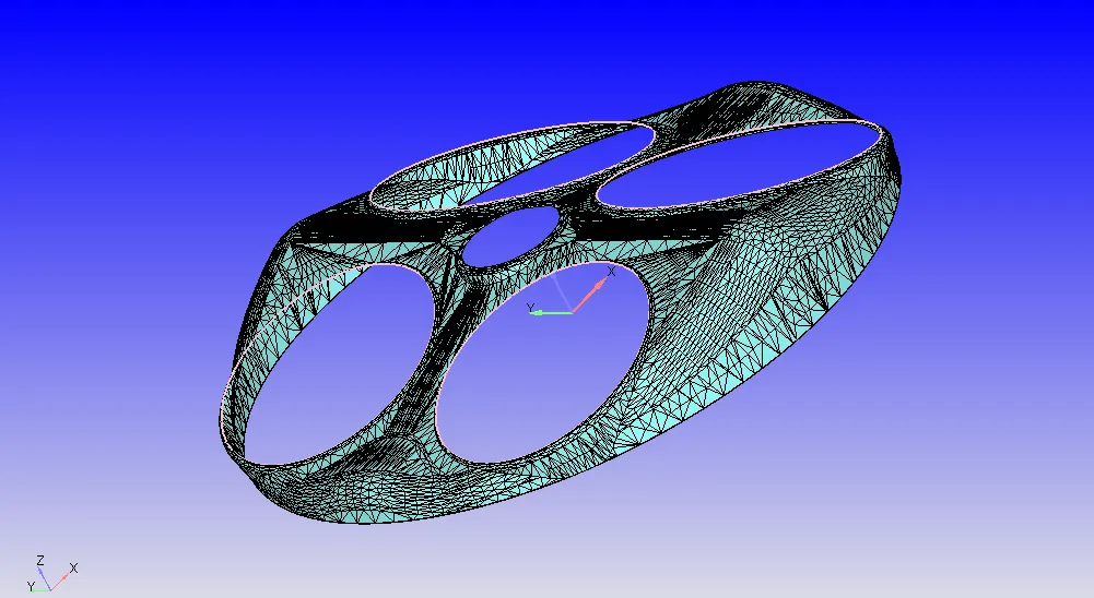
Spark plug:
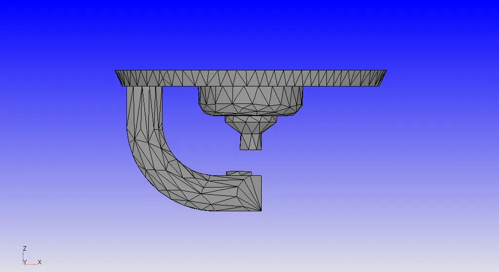
FINAL GEOMETRY:
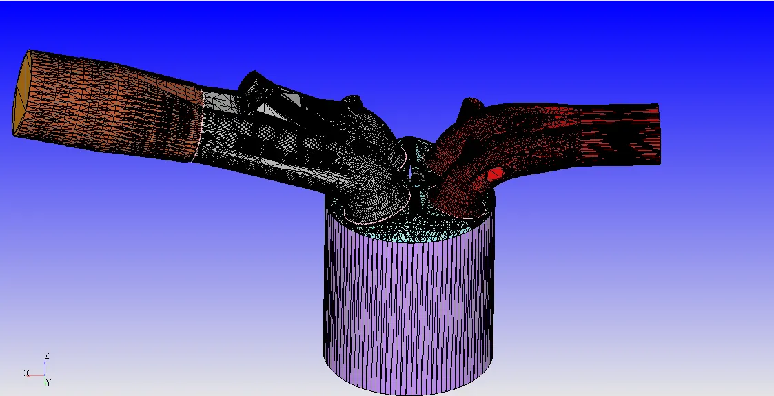
After doing the case setup by provding fixed Embedding for the geometry looks like the below image
INTRODUCTION:
-Port Fuel Injectors is one of the most widely used Fuel Injection system.
-Port fuel injectors, The air and fuel are combined outside the combustion chamber i.e, at intake manifold. From there the mixture flows through the intake tract and intake valve to the combustion chamber. Since the fuel is injected right before the cylinder, most of the fuel will drawn into the cylinder causing less collection of fuel in the manifold and the intake manifolds for PFI engines are not necessary to be made of metal as intake mostly contains air at atmospheric pressure. this can reduce the weight of the engine.
-In this simulation of Port fuel injection Ico Octane fuel is used as fuel which has same properties as gasoline.
-Full hydro case setup with transient case is done for the simulation.
THEORY:
Converge CFD:
Converge CFD is a complete package that was designed for simulating engine based applications. Now it has emerged as top software for many CFD applications. like IC engines, Oil and gas, compressors fans and blowers, Gas Turbines etc.,
Combustion Modelling:
-Combustion facilitates the energy tranfer in an engine. Converge contains detaied chemistry solver and simplified combustion models.
SAGE detailed chemistry solver:
-Most predictive and accurate way to model combustion
-Accurately model ignition and laminar flame propagation
Simplified Combustion Models:
-Generally less computationally expensive and predictive than SAGE
-May provide acceptable resulta for specific applications
SAGE:
- It is detailed chemistry solver that accurately models ignition and falme propagation.
- It solves detailed chemical kinetics during combustion and determines kinetically limited engine knock and emissions.
-Uses Local conditions to calculate rates based on principles of chemical kinetics.
-Each time-step, the chemistry solver calculates the new species mass fractions immediately prior to solving the transport equations.
-solving detailed chemistry in every cell can be expensive.
-Converge includes options to reduce the compuatational time by Increase the minimum cell temperature and minimum HC species mole fraction to reduce number of cells in which combustion calculations are performed
Mutizone model:
Multizone reduces the number of SAGE calculations by.
-Grouping cells into bins.
-calculating average quantities
-Mapping solved quantities to all cells in bins.
-Invoking the SAGE solver once per bin instead of once per cell.
Spary Modelling:
In converge It solves both liquid and gaseous sprays
State of art models for spray Process including liquid atomization, drop breakup,collision and coalescence, turbulent dispersion, and drop evaporation.
To perform detailes anlysis of spraying for accurate results
Lagrangian based model is used for spray modelling this is mathematical equations for solving spray.
gaseous sprays, converge uses Eulerian solver sets the species mass fractions and mass flow rate at the INFLOW boundary
Liquid sprays, converge uses lagrangian solver to model discrete parcels and the Eulerian solver to model the continuous fluid domain.
Heat, momentum and mass transfer occur between the discrete and continuous phase cia soure terms and transport equations.
Parcels:
Collection of drops into domain at the injector. Each parcels represents a group of identical drops coverge solves as per parcel basis and not per drop basis(because the drops in parcels are identical. The parcels Statically represents the entire spray field.
It undergoes several physical process
-Primary breakup
-secondary breakup
-Drop drag
-collision and coalescence
-Turbulent dispersion
-Evaporation
Sub grid modelling:
When fuel injection takes place Due to interaction of liquid with surrounding tends to drag force which causes disturbances in length when it occurs breakup should occur.
-Primary break up means to break up parcels into small parcels and it break up further and tends to secondary breakup and the tiny parcels interact with the ambient air shapes could affect and it causes vaporization that is called drop drag and it is larger drop and gets evaporated in some instance and it looks like a tiny drop this process is due to evaporation. Fluctuating velocity in gas phase how does it affects the drop known as turbulent dispersion.
Spary modelling:
-Here Ico octane is used as parcels this has same configuration like gasoline
-Converge assumes the injectio is in conical shape. Pracel distribution is distributed evenly through out the cone.
Evaporation modelling:
-Selecting the desired method for calculating the drop radius rate of change and rate at which mass is transfered. Frossling model is used
Evaporation source:
-Selecting Evaporation source to specify how converge simulates multi-component vaporization
-Source Specified species - Parcels evaporate to the specifeid species
-Soure all composite parcel species - If composites defined,multi-component liquid species evaporate into composite species. If it is not defined species evaporate into base species.
-Source of all base parcel species- Multi-componet liquid species evaporate into base species(for both composite and base species.
-Maximum radius is provied for ODE Droplet heating, which will control if the drop temperature is uniform or radially varying.
Spray Penetration:
-When fule is injecting some of the fuel is vapouraize if ambient temperature is high. Initially,Lquid is penetrating in to domain and at certain time it converts to Steady state and no longer pentration is happen.
-For liquid penetration length specify the liquid fuel mass fraction for the injector. converge calulate spray penetrated mass by total liquid mass by the total liquid mass in the domain.
-For vapour penetration length for each nozzle. Converge calculates fuel vapour mass fraction in each cell inside the spary cone.
Collision/Coalencence:
No two parcels never collide they can only pass through each other.
Drop collison Options:
-O'Rourke numerical algorithm
-NTC numerical algoritm
Outcome options:
-O'Rourke collision outsomes
-Post collision Outcomes
Collison Mesh:
-parcels can collide only with parcels in the same cell which can lead to grid sensitivity. converge has an adavtive mesh collision option to reduce grid sensitivity.
Drop wall interaction:
-Rebound/slide- Drops rebound or slide along the wll after impingement.
-Wall film - Drop actions are calculated with hybrid approach based on particle-based quantities or film-based quantities
-Vanish- Drops vanishes after hitting a wall boundary.
Drop Drag:
when parcel is entering into the domain it encounters air resistance
-Spherical drop drag - The drag coefficient calculation assume the drops are perfect sphers
-Dynamic drop drag - The drag coefficient calculation accounts for variation in the drop shape. This model invokes the TAB model to determine the drop distortion.
Regions and Events:
Region is a collection of boundaries used to delineate different areas in geometry.
Regions helps for variety of reasons
-specifying initial conditions by regions.
-control flow between the regions
-specify combustion models by events
-output results on a region-by-region basis
Events:
Events are used to close and opening of two boundaries. when 2 regions are in contact with each other with no boundary in between events are used. The events creates traingles in the place between the 2 regions called Disconnect triangles.
Disconnecting Traingles:
Disconnect traingles are created by the converge itself when solving but provide the events correctly.
Impotance of Interface:
The interface that are very important in disconnecting the traingles they should not intersect with any of the geometry.
Ring Triangles:
Ring Traingles are used for the valves which are connect to the manifold this helps in the movent of valve if ring triangles are not provided valves movement takes place with the movement of manifold but movement of manifold does not makes sense so fro making the valve movement ring triangles are made.
Adaptive Mesh Refinement:
AMR inputs a parameter sub grid scale which refines the mesh size when the curvature of the selcted parameter goes beyond the set value. SGS can be applied on any of the parameters.
- AMR automatically increases the grid resolution based on curvature(second derivatives in field variables.
- AMR can be permanent or activated at specific times.
Converge calculates Sub-grid scalar field as `phi' = phi-phi^_`
phi'= sub-grid scalar field
phi= is actual field
phi^- = is the resolved field
converge uses truncated infinite series to approximate the sub-grid field for any scalar
`phi' = -dx^2/24(partial^2phi^-)/(partialx^2)`
dx^2 is grid spacing
CASE SETUP:.
Crank angle-based:
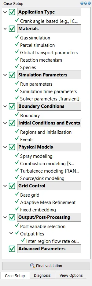
Physical Parameters like bore, stroke, connecting rod length are shown in the below image.
Materials:
Gas Simulation:
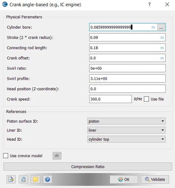
In this IC engines are basically gas simulation so gas simulation is enabled in materials section and provided fluid properties.
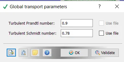
Global Transport Parameters:
There parameters are set as default values.
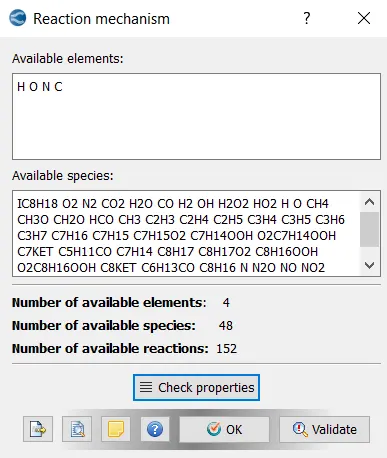
Reaction Mechanism:
These mechanisms are used to provides the elemts species and reactions of the material properties.
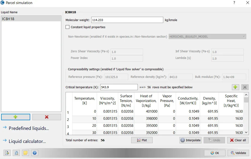
Parcel simulation:
Ico octane is used as parcel species.
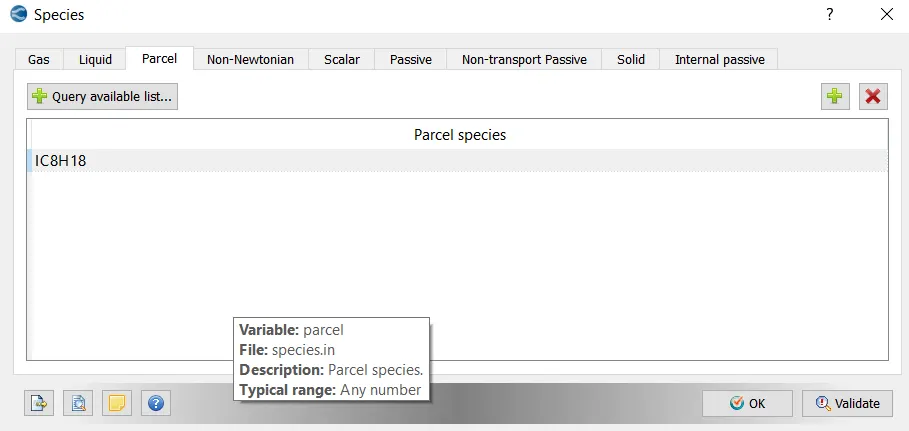
Species:
Parcels:
Parcels are the collection of drops. The fulid is lagrangian based spray model Ico Octance flel is used as parcel in PFI Engine.
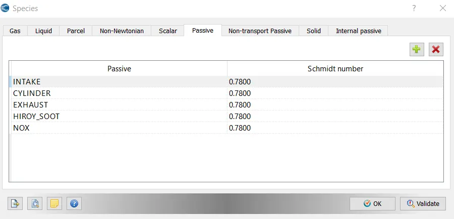
Passive:
Quantity computed in a given cell. It can also be solved transport equations but donot affect the flow field. It helps in visualizing the givien passives during post processing.
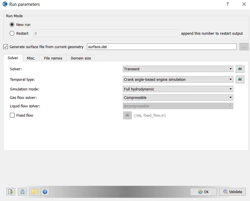
Run Parameters:
Full hydro Transient solver is used for this simulation.
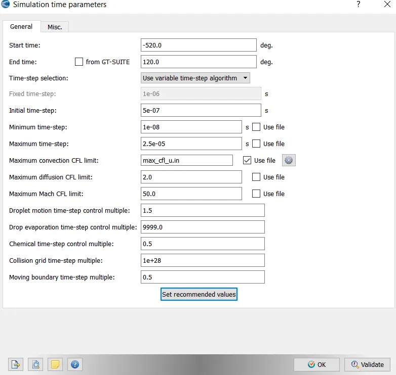
Simualtion time parameters:
Start time and end time is givena and as this is crank angle based simualtion time is given in degrees.
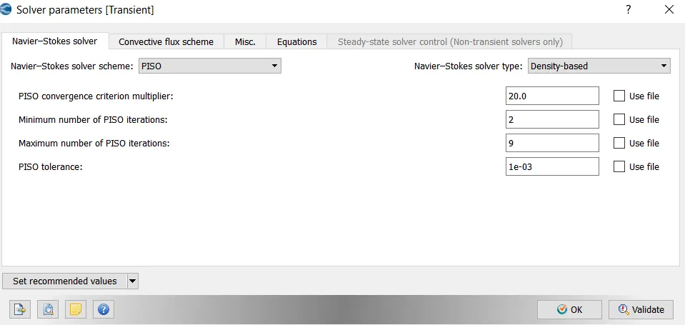
Solver Parameters:
PISO solver is used to calulate the navier stokes eqaution as this is pressure based velocity coupling method to solve pressure equations in Navier stokes eqaution and density based solver is used because this type is used for high speed compressible flows.
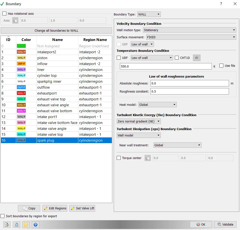
Boundary Conditions:
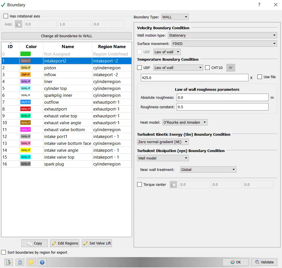
Intake Port2:
Wall motion is sationary and surface movement is fixed.
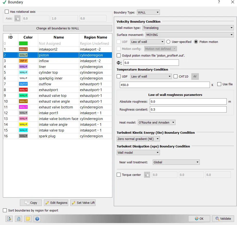
Piston:
Wall motion type is translating and suface is moving.
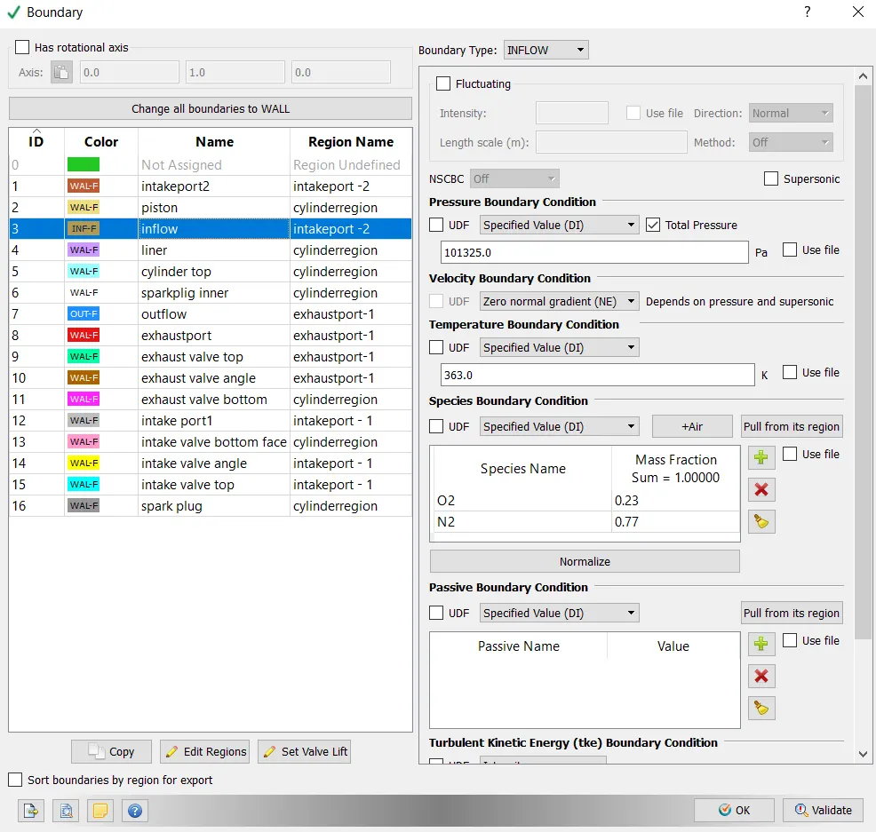
Inflow:
Pressure boundary condition is specified as total pressure(101325) and Temperature is specified as 363k.
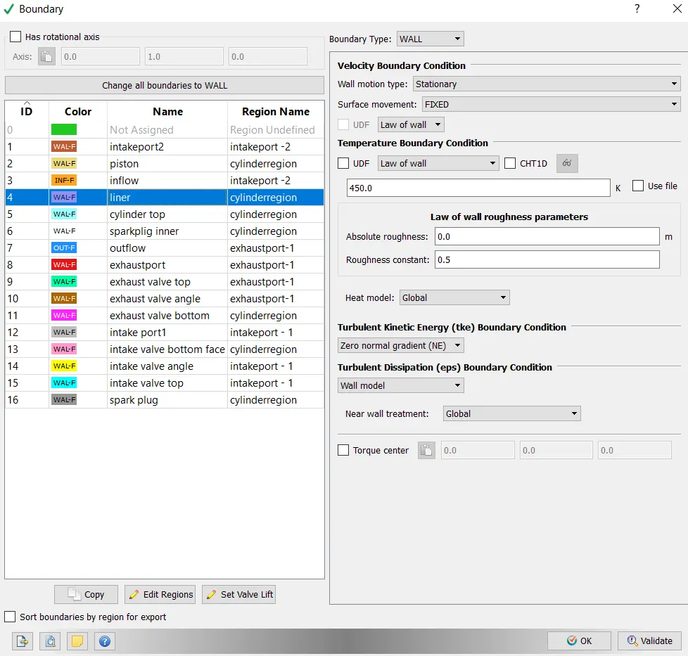
Liner:
Wall motion is sationary and surface movement is fixed and Temperature is specified as 450k.
Cylinder Top:
Wall motion is sationary and surface movement is fixed and Temperature is specified as 450k.
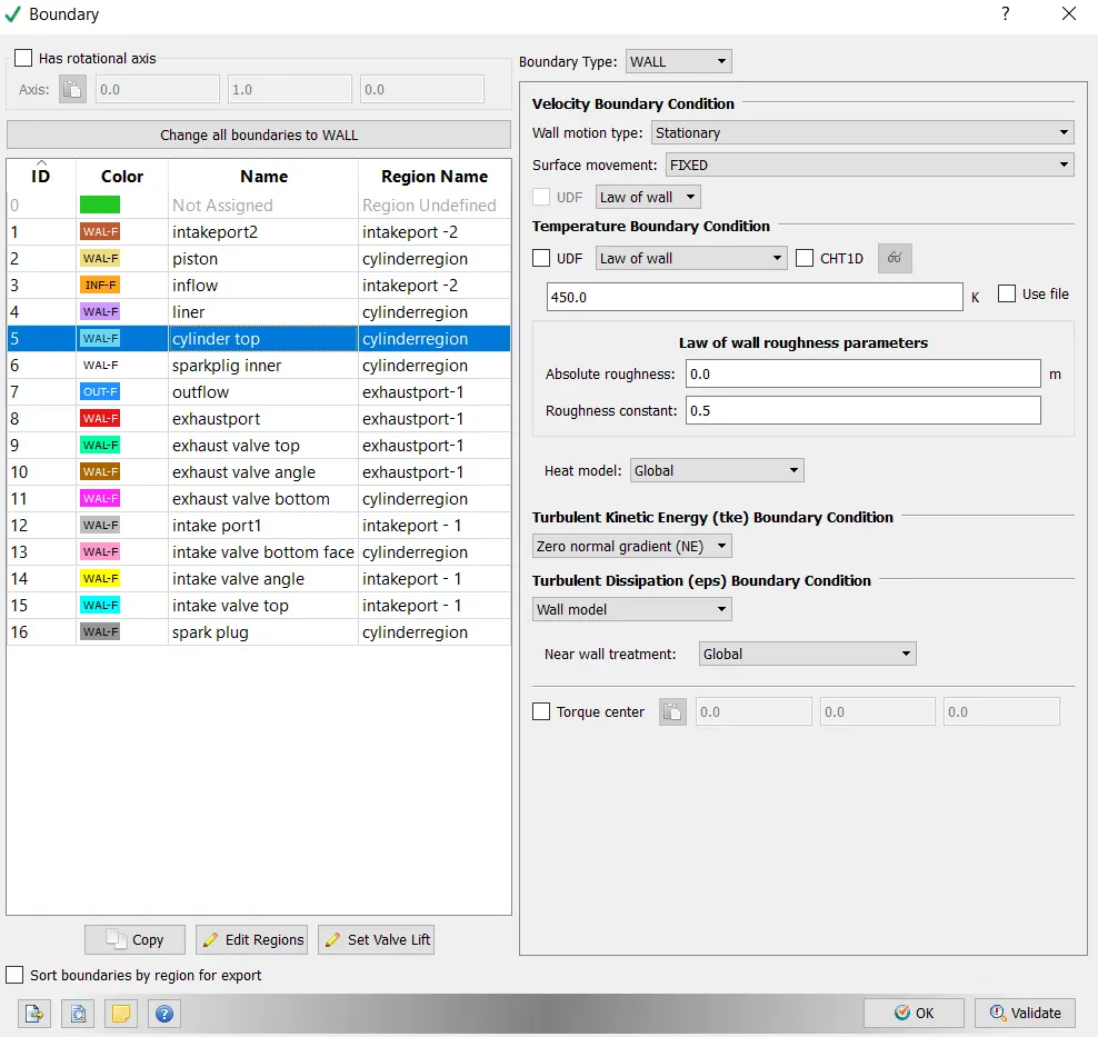
Sparkplug liner:
Wall motion is sationary and surface movement is fixed and Temperature is specified as 600k.
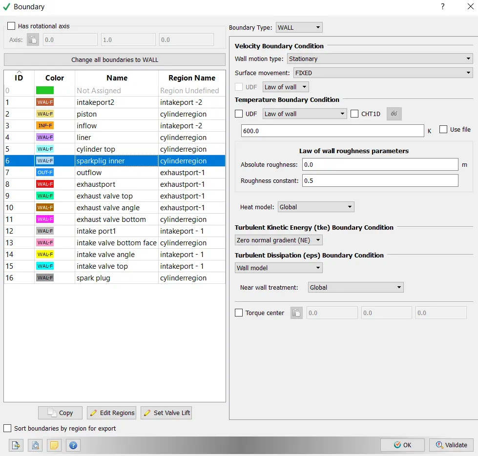
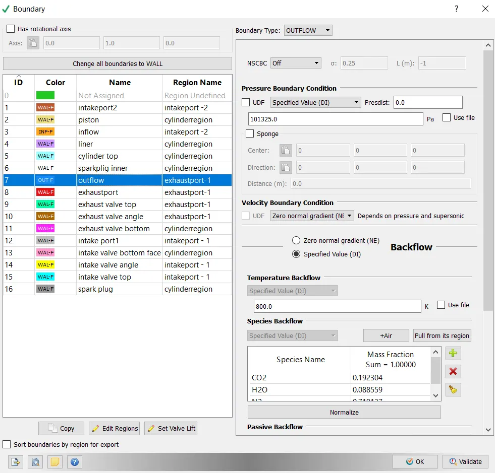
Outflow:
Pressure is specified (101325) , Temperature is specified as 450k.
Stiochiometric eqaution = C8H18 +12.5(O2+3.76N2) --- CO2 + 9H2O + (3.76*12.5)N2
mass = MW*moles
mass fraction = mass of particular species/ total mass
mass fraction of CO2 = 352.08/1830.847 = 0.192304
mass fraction for all the species is equal to 1 as this is balanced and done using stiochiometric .
| Species | moles | MW(g/mol) | mass | mass fraction |
| CO2 | 8 | 44.01 | 352.08 | 0.192304 |
| H20 | 9 | 18.01528 | 162.1375 | 0.088559 |
| N2 | 47 | 28.0134 | 1316.63 | 0.719137 |
= 1830.847 = 1
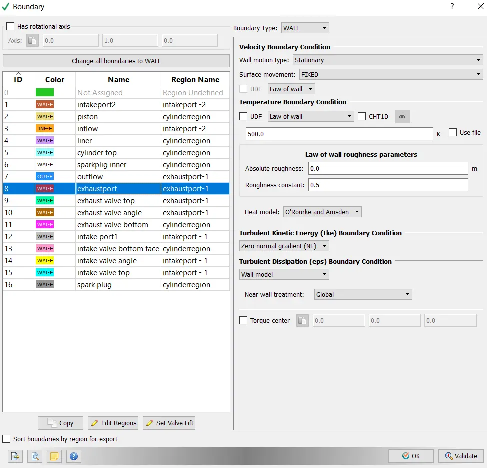
Exhaust port:
Wall motion is sationary and surface movement is fixed and Temperature is specified as 500k.
Exhaust Valve Top:
Wall motion is Translating and surface is moving and Temperature is specified as 525k.

Exhaust valve angle:
Wall motion is Translating and surface is moving and Temperature is specified as 525k.
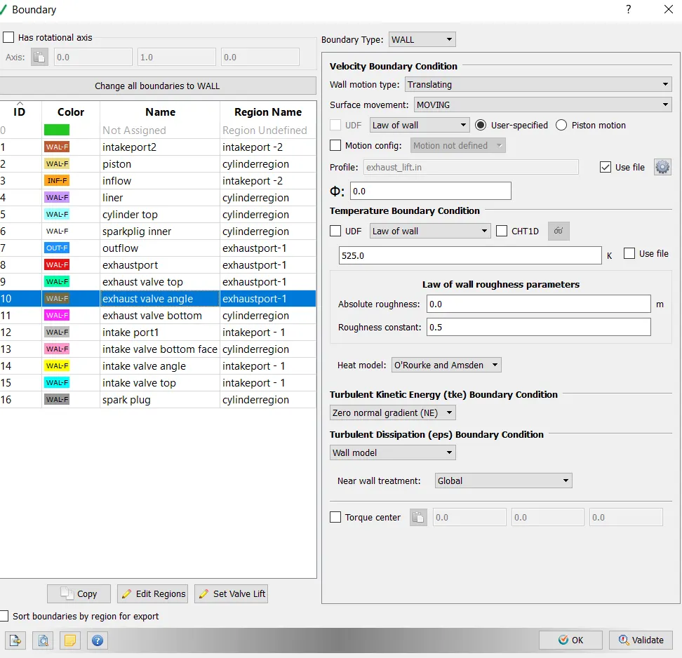
Exhaust valve bottom:
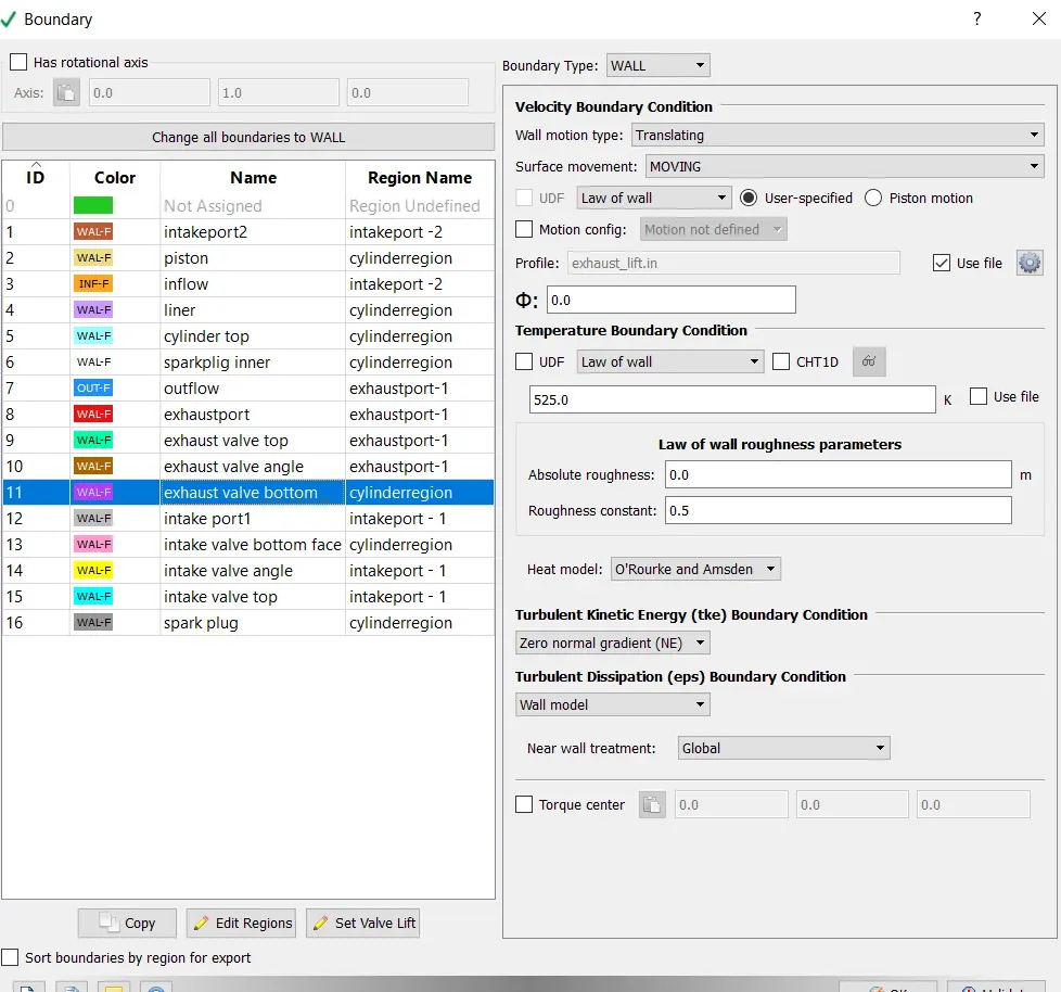
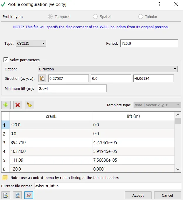
Exhaust lift:
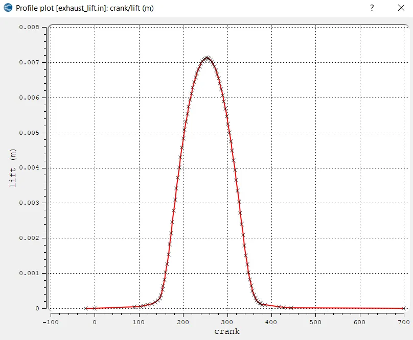
Profie plot for Exhaust lift:
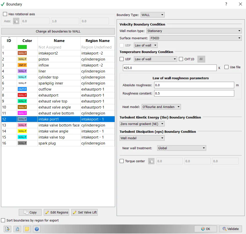
Intake port:
Wall motion is stationary and surface is fixed and Temperature is specified as 425k.
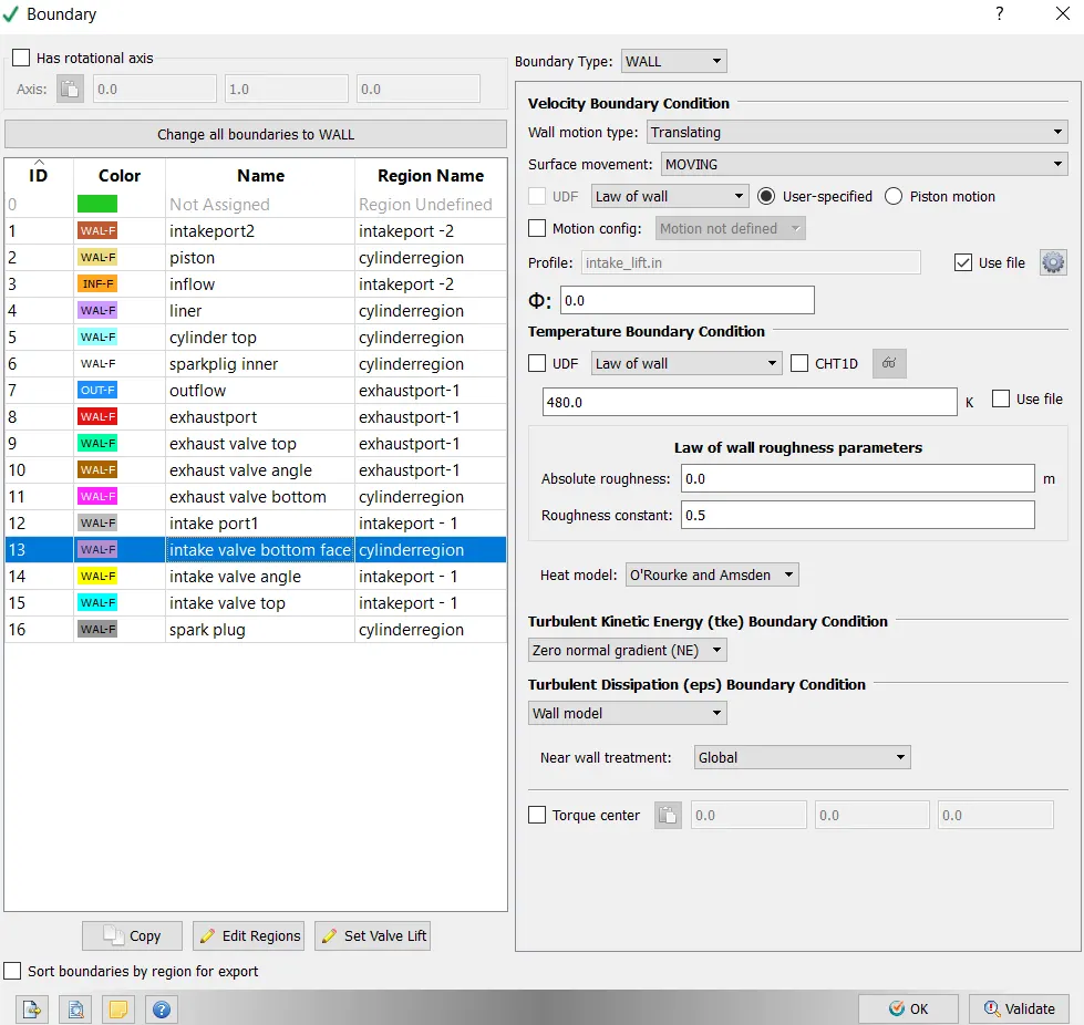
Intake Valve bottom:
Wall motion is Translating and surface is moving and Temperature is specified as 480k.
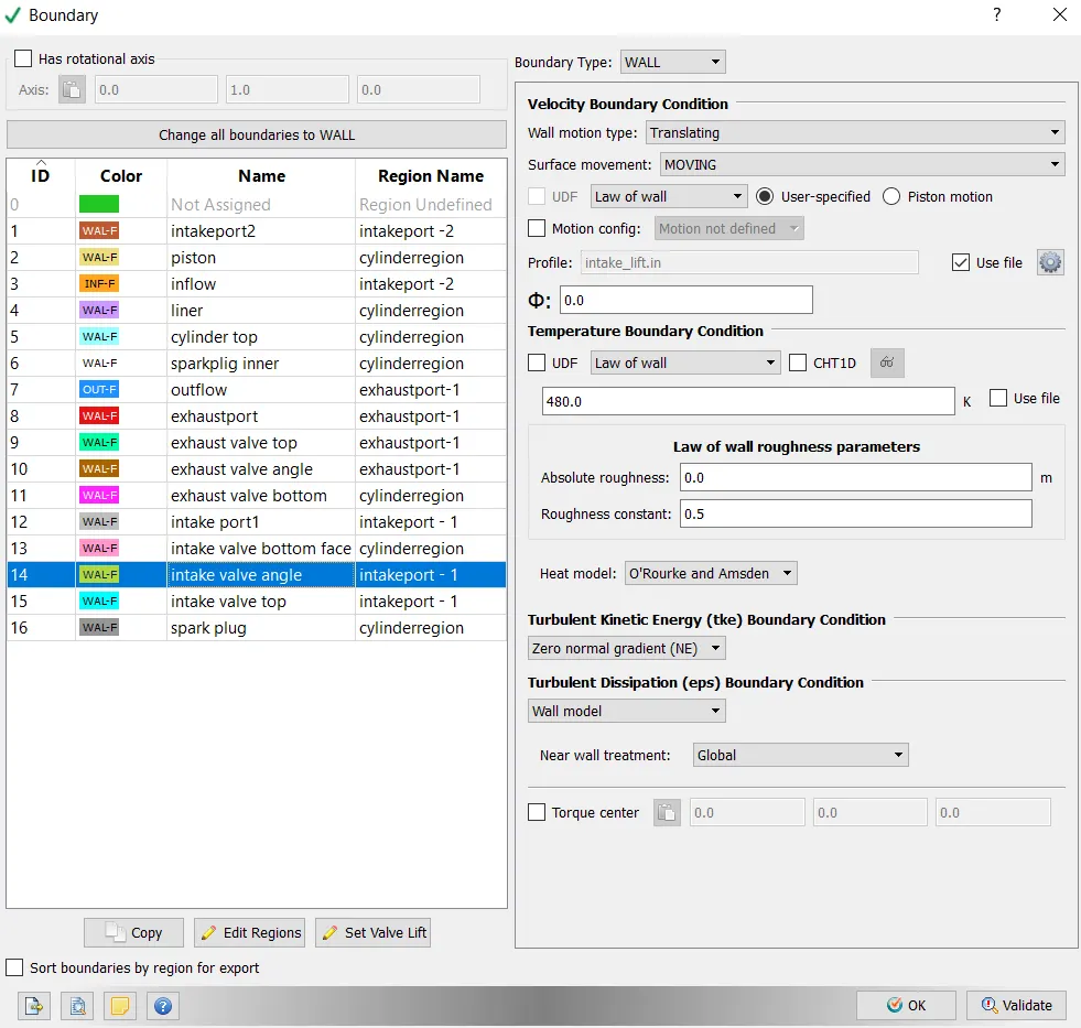
Intake valve angle:
Wall motion is Translating and surface is moving and Temperature is specified as 480k.
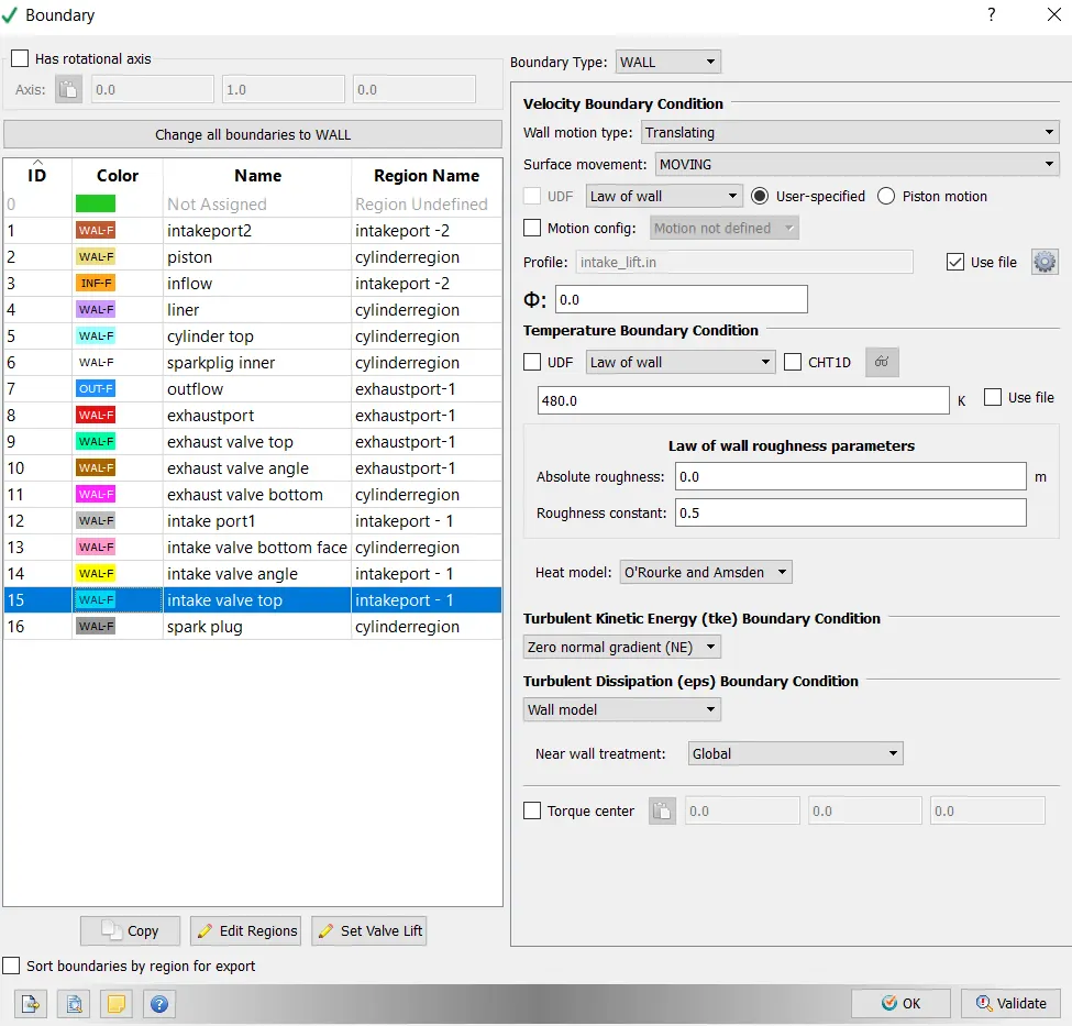
Intake valve top:
Wall motion is Translating and surface is moving and Temperature is specified as 480k.
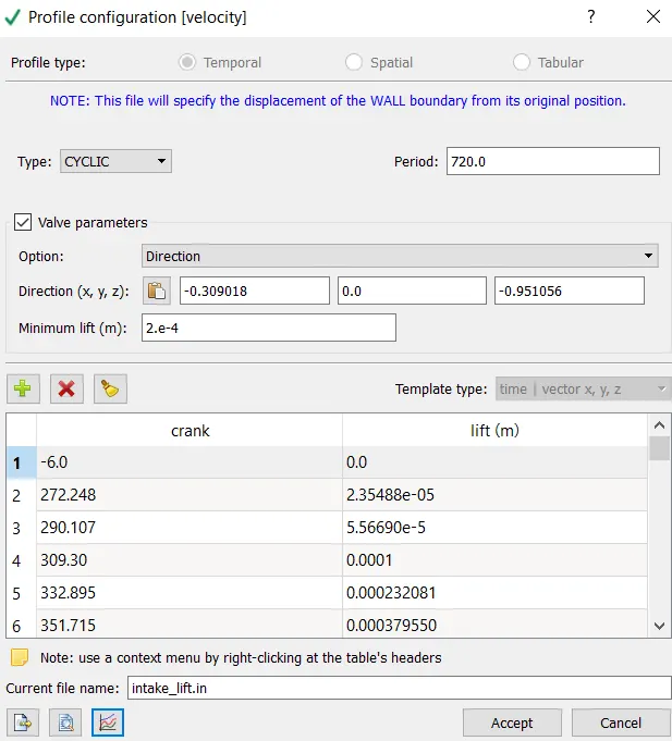
Intake lift:
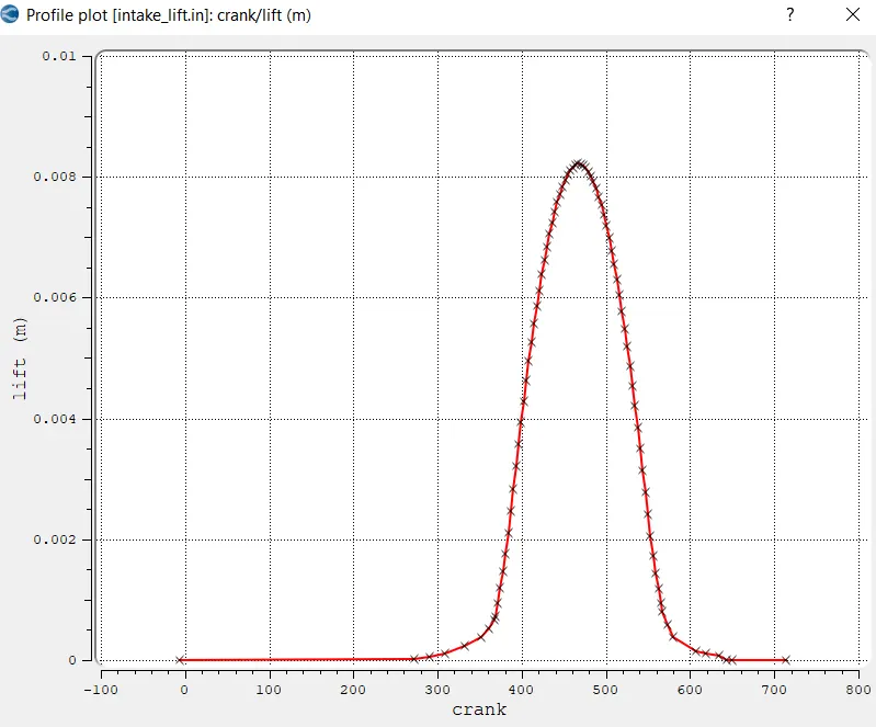
Profile plot for Intake Lift:
Spark plug:
Wall motion is stationary and surface is fixed and Temperature is specified as 550k.
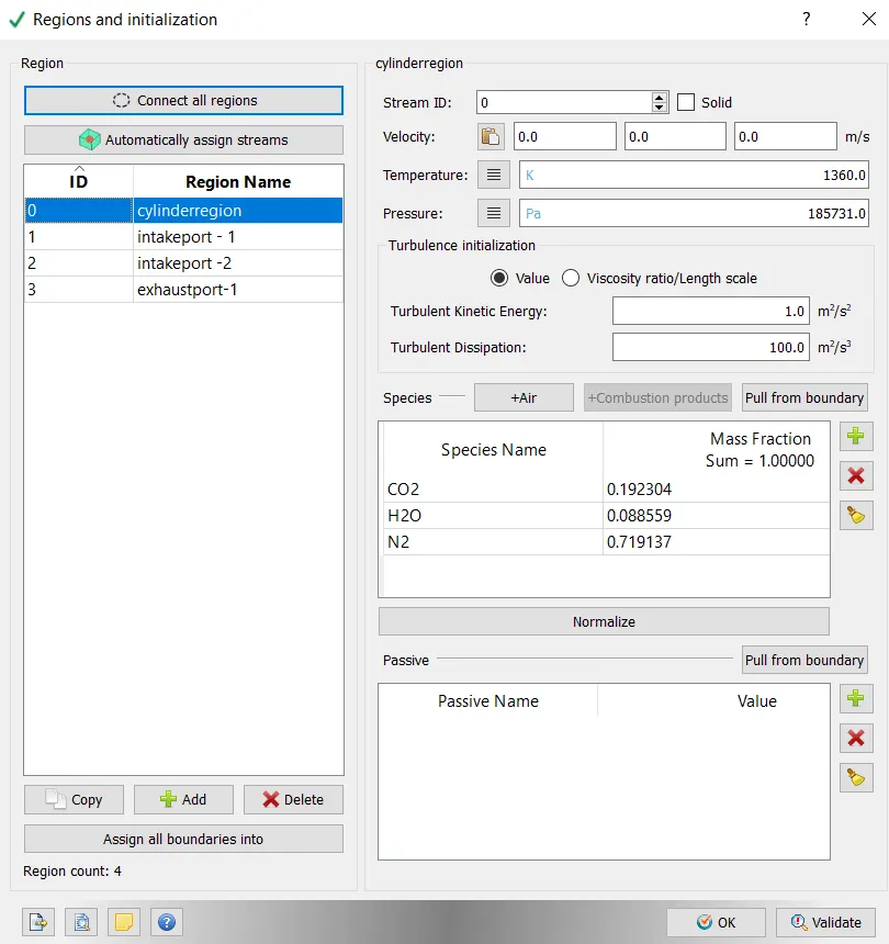
Region and Initialization:
Cylinder Region:
Pressure and Temperatures are specified and species (CO2,H20,N2) is equal to mass fraction 1
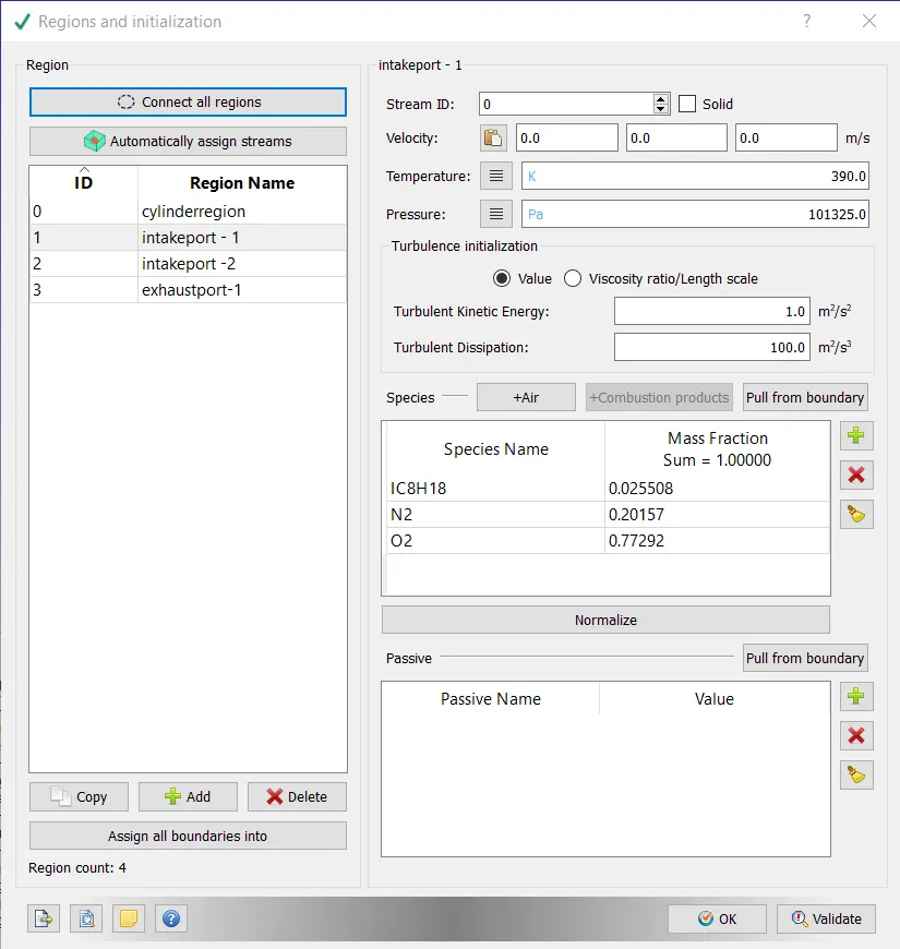
Intake port1:
Pressure and Temperatures are specified and species (IC8H18,02,N2) is equal to mass fraction 1
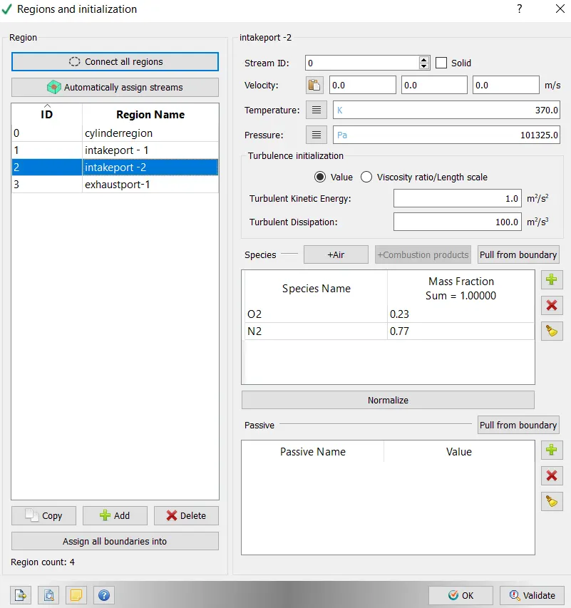
Intakeport 2:
Pressure and Temperatures are specified and species (O2,N2) is equal to mass fraction 1
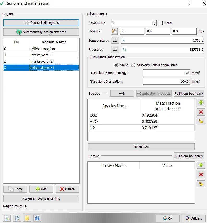
Exhaustport:
Pressure and Temperatures are specified and species (CO2,H20,N2) is equal to mass fraction 1
| Species | moles | MW(g/mol) | mass | mass fraction |
| CO2 | 8 | 44.01 | 352.08 | 0.192304 |
| H20 | 9 | 18.01528 | 162.1375 | 0.088559 |
| N2 | 47 | 28.0134 | 1316.63 | 0.719137 |
= 1830.847 = 1
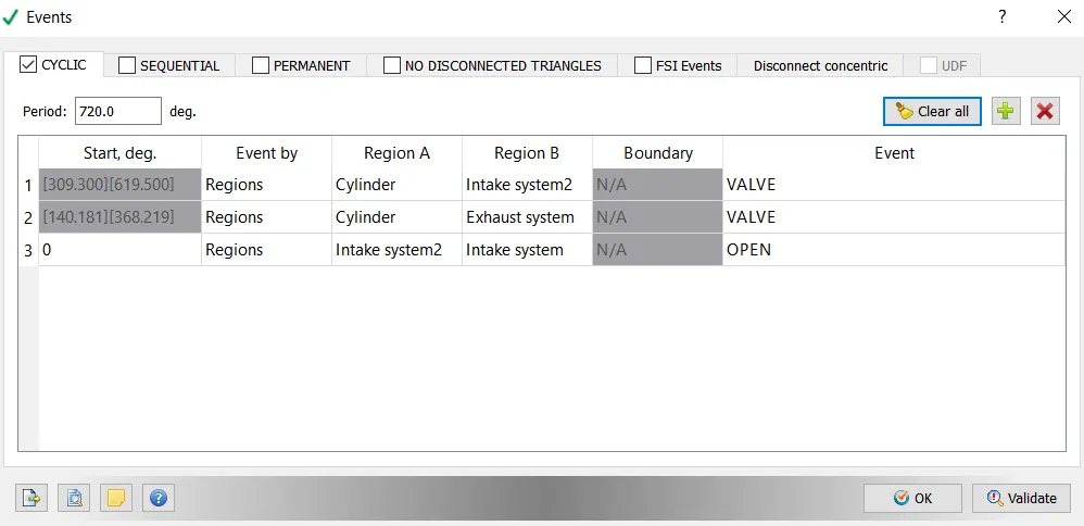
Events:
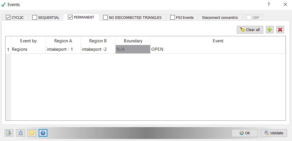
Events helps to open and close for a given regions amd for particular period. In an IC engines, converge uses concentric circle disconnection to control the flow between the cylinder and the port regions.
Close Events: Intake valve closing, exhaust valve closing.
Open Events:
Intake valve opening, Exhaust valve opening
For these events, specify Cyclic and period.
Permanent:
Spray modelling:
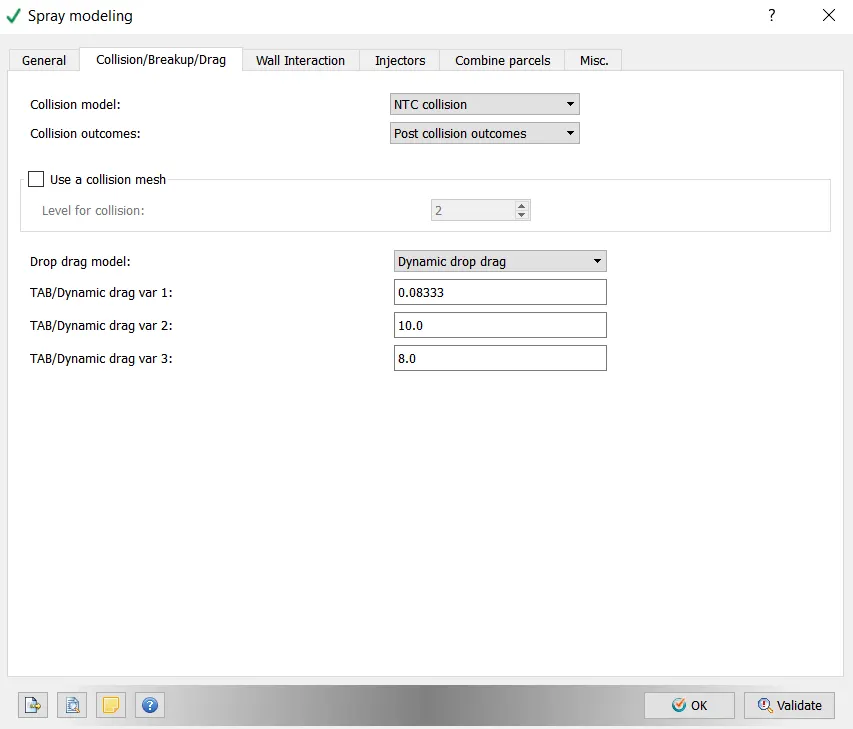
Dynamic drag model with default values is used.
Wall Interaction:
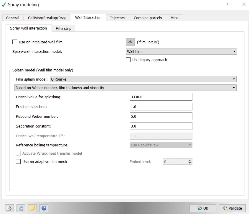
Spray wall interaction model is wall film this is mainly used model and splash film model is O'ROurke.
General:
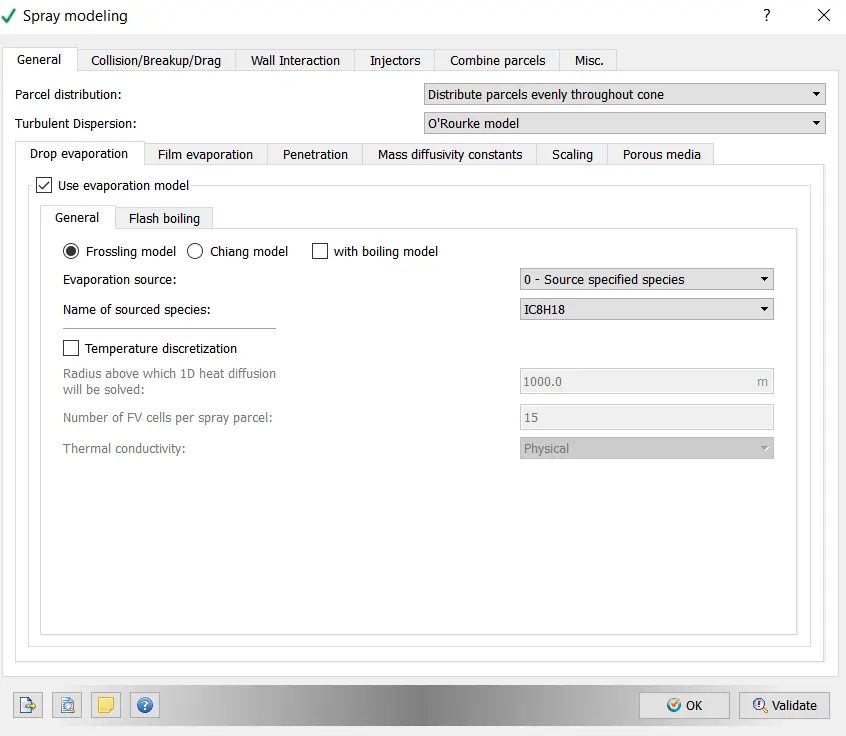
Distribute parcels evenly through out the cone is used for parcel distribution and O'Rourke model for turbulent dispersion. For evapouration model Frossling model is used.
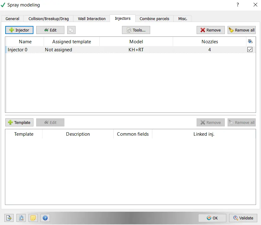
Injectors:
specifying injector in the intake port manifold.
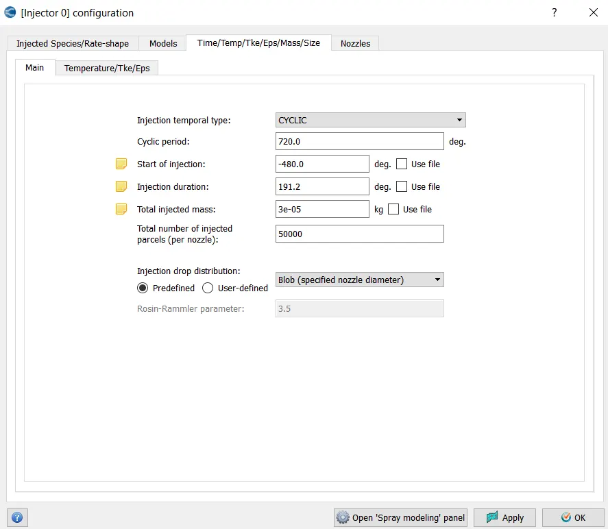
Injector Configuration:
Cyclic Injection with star of injection is at -480 deg and duration of injection is 191.2 deg and Total mass Injected 3e-05 kg and number of parcels injected is about 50000.
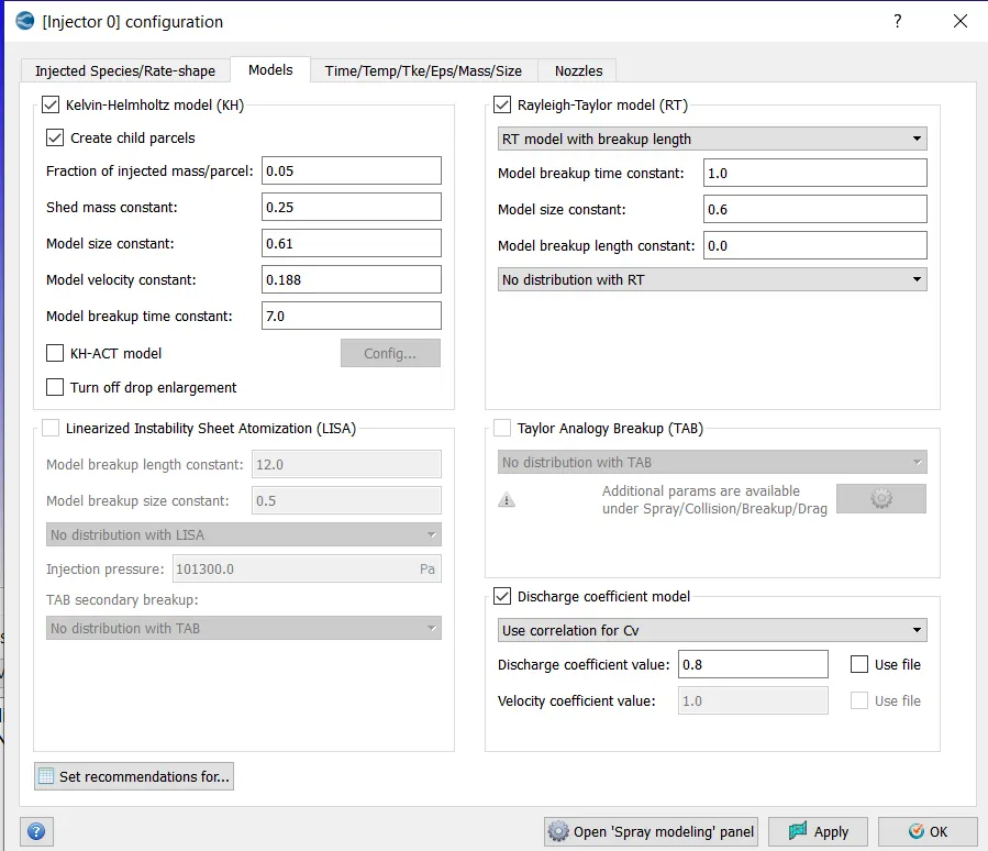
Models:
Kelvin Helmolz and Rayleigh taylor model is used
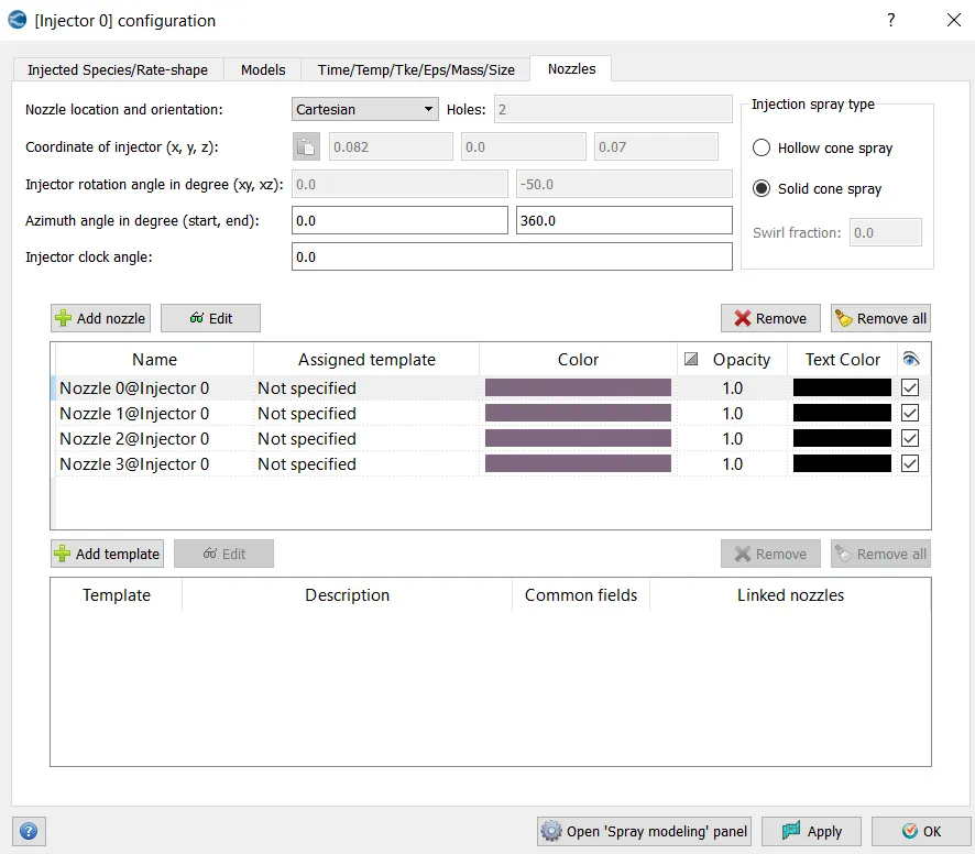
Nozzels:
Four nozzles is created because when injection takes places are transported through nozzles into the combustion chamber.
Combustion Modelling:
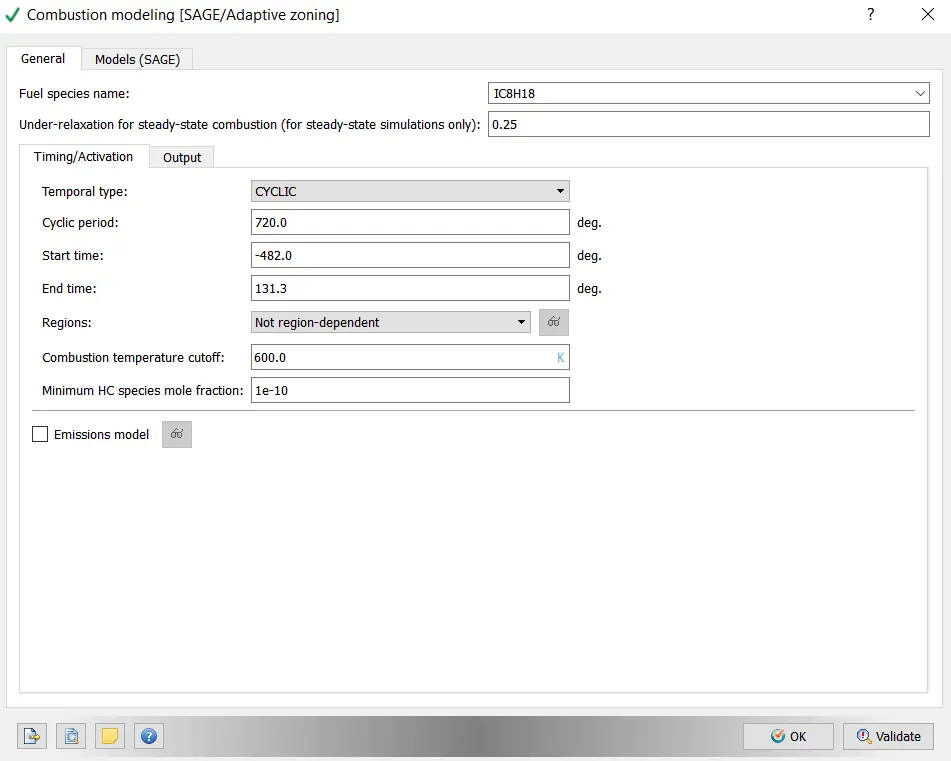
Cyclic type and combustion statrs at -482 deg and ends at 131.3 deg and not region dependent with minimum HC species of 1e-10.
SAGE:
Adaptive Zoning:
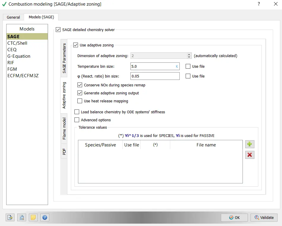
In combustion modelling the simulation takes place through bins and not at each computational cell and the total temperature bin size is 5 with the reaction ratio of 0.05. SAGE helps to create bins with adaptive zonig.
SAGE Parameters:
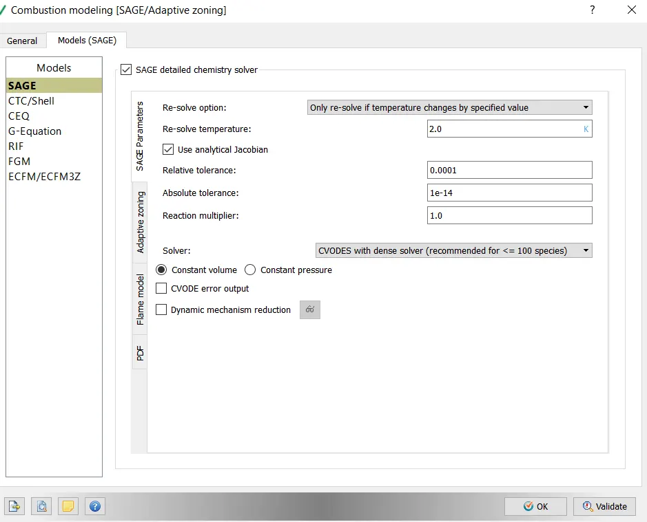
CVODES are the ODE solver to calculate the rate of species of reaction mechanism.
Turbulence Modelling:
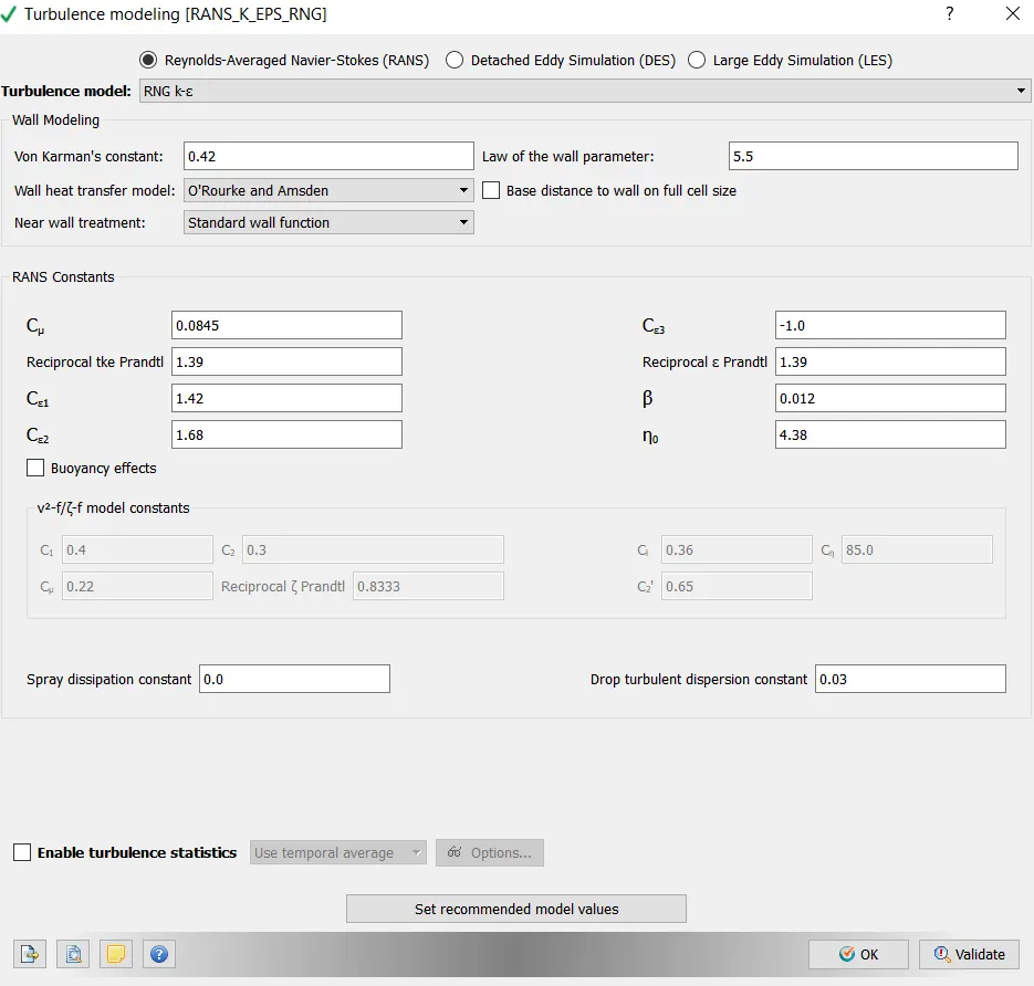
RNG k-epsilon turbulence model is used for this PFI engine.
Source/sink Modelling:
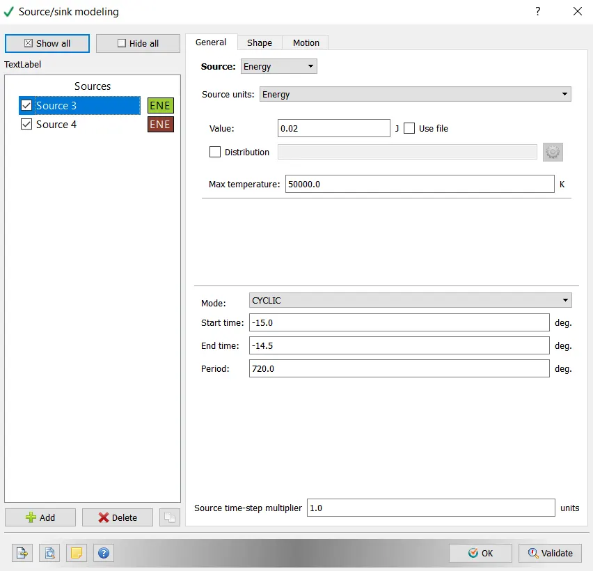
Cyclic mode with -15 deg start time and -15.5 deg end time. This is basically energy eqautions this increases the temperature of the species in species transport eqaution this is introdued as a source term produces more species reduces the temperature in the enrgy eqaution and then increase the temperature again.
Base grid:
Adaptive Mesh Refinement:
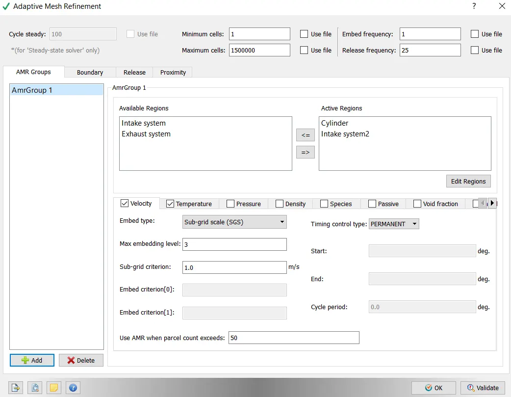
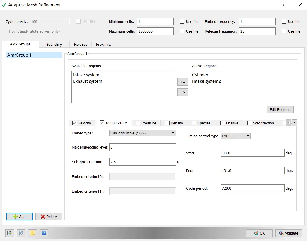
Adaptive mesh refinement is done for velocity and temperature it analyses the curvature and redues the mesh size at particualr regions for a given Embedded type, Max embedding level and Sub-grid criterian
velocity:
SGS
Max embedding level = 3
Sub-grid criterian = 1.0
For velocity the sub-grid criterion is minimum value should 1 to calculate AMR and type is permanent
AMR is done for cylinder and intake system
Temperature:
SGS
Max embedding level = 3
Sub-grid criterian = 2.5
Type is cyclic at start time is -17 and end time is 131
AMR is done for cylinder and intake system
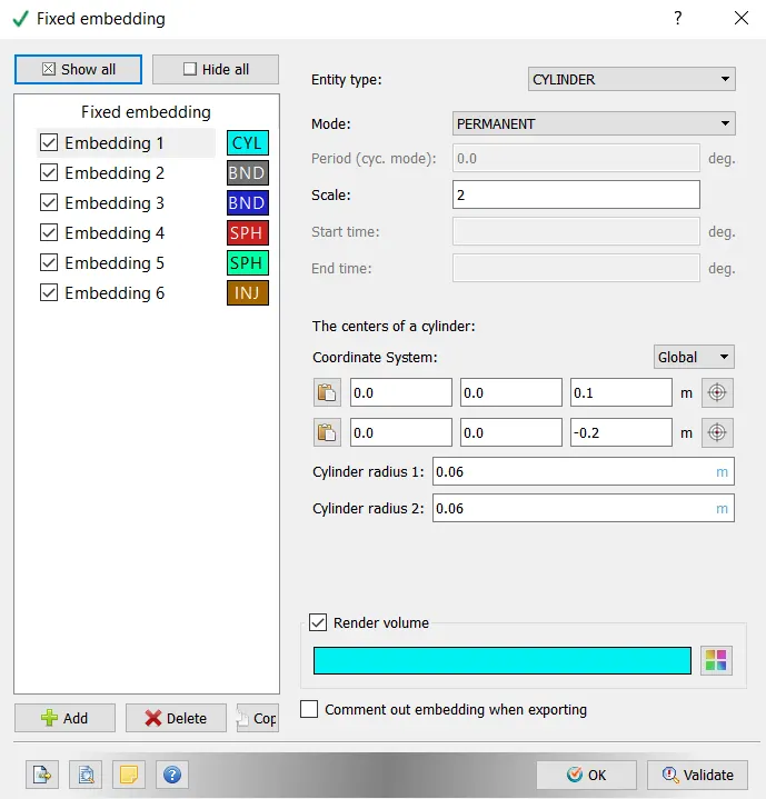
Fixed Embedding:
Cylinder:
Permanent mode scale of 2 and the coordinate system is provided.
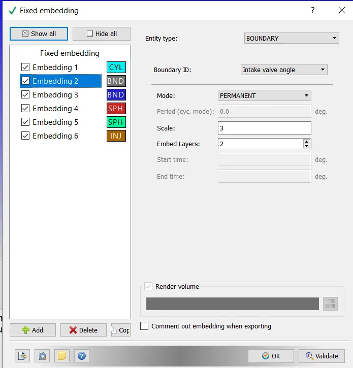
Boundary Inlet valve angle:
Permanent mode scale of 3, embedded layers of 2 and the coordinate system is provided.
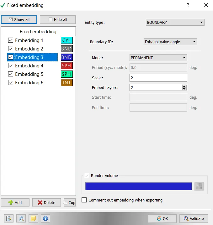
Boundary Exhaust valve angle:
Permanent mode scale of 2, embedded layers of 2 and the coordinate system is provided.
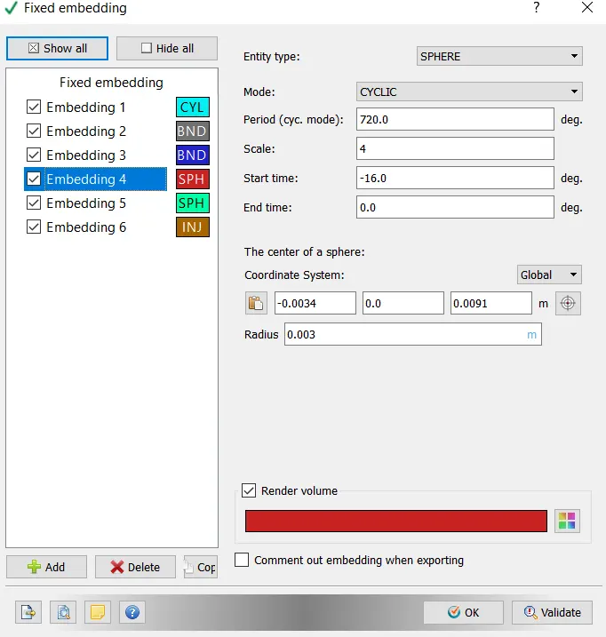
Sphere cyclic (spark plug):
Spherical cyclic mode with a scale of 4 and start time is -16 near the spark plug is provided.
Sphere cyclic (spark plug):
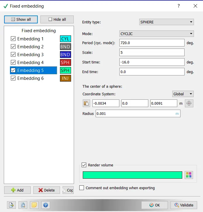
Spherical cyclic mode with a scale of 5 and start time is -16 near the spark plug is provided.
Injector:
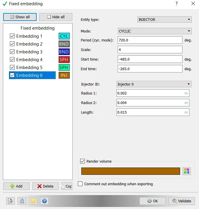
Spherical cyclic mode with a scale of 4 and start time is -485 and end time is -265 for the Injector is provided.
Fuel mass:
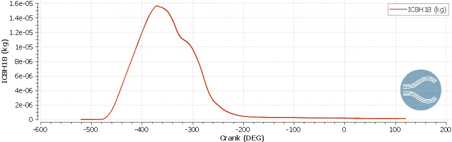
Mass of the fuel is shown in the below graph represents the release of mass from starting of crank to the end and the increase of mass from -500 to -390 and then it gradully decreases and came to steady state where the injection of fuel is no taking place.
Hiroy soot:
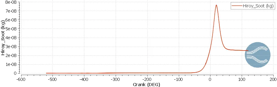
Hiroy soot is basically an incomplete combustion the graph represents the overall crank angle from starting to end and the incomplete combustion is taking place between -10 to 40deg where the combustion is taking in that crank angle.
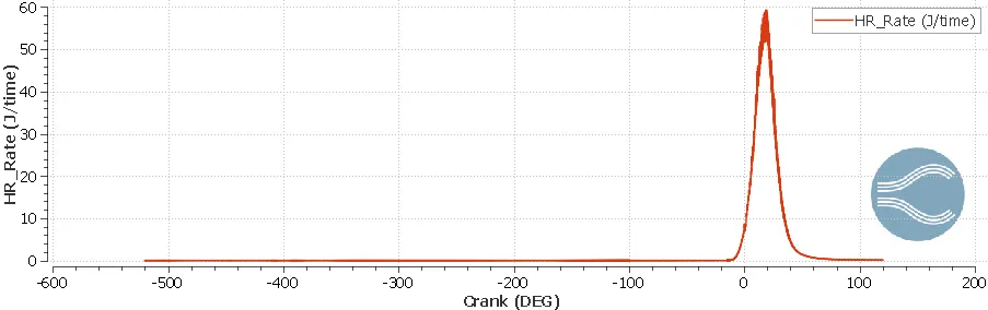
HR:
HR is energy released from the PFI when it undergoes combustion process from -10 to 40 deg the energy increses as the combustion is taking place in that crank angle.
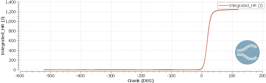
Integrated HR:
Intergrated Hr is the release of energy from the engine the maximum value at the end timestep helps to calculate the power output.
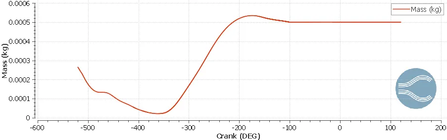
Mass:
The graph represents the mass in PFI engine from the starting of the crank to the end the increase of mass from the -460 to -210 deg and then decreases slightly and then came into steady state.
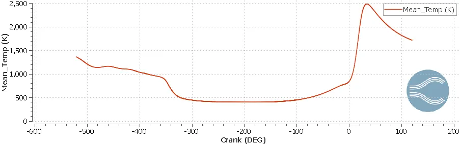
Mean temperature:
The below plot represents the mean temperature of PFI engine Full hydro simulation from Starting of the crank angle to the end of the crank the temperature increses when the combustion takes places as this is clearly visible in the plot.
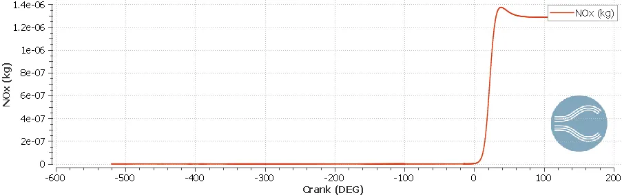
NOx:
Nox are the emissions release from the simulation of PFI engine but those are small emissions that doesnot have any effect as this not experimental the release of NOx from the ENgine takes place after the combustion.
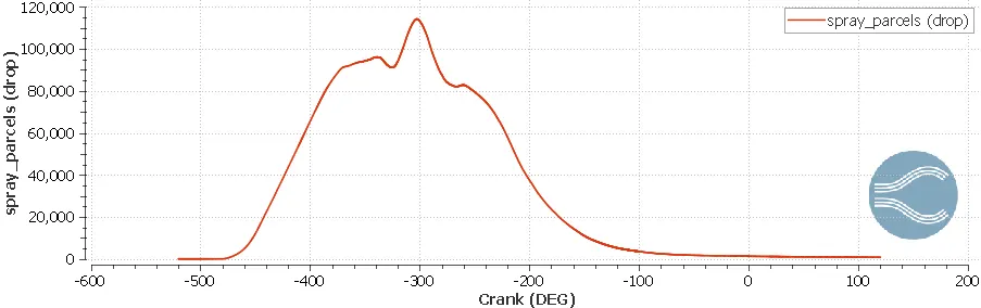
Parcel drops:
Parcel drops are the collection of fuel drops or spray parcels in PFI engine the below plot represents the Injection of the parcels into the domain.
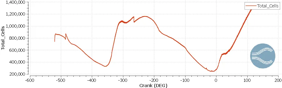
Total cells:
The changing of total cells for timestep due to changing of Adaptive Mesh Refinement
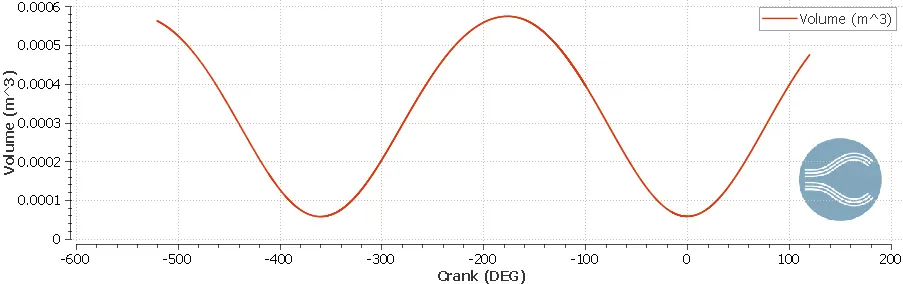
Volume:
This helps in analysing the maximum clearence and minimum cleasrence values to get the compression ratio.
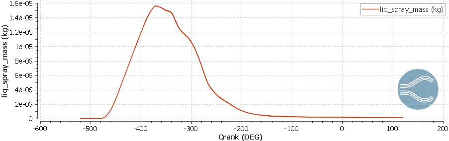
Spary mass liquid:
Liquid spray mass In PFI engine with the help of injectors and nozzles the Liquid spary into the domain is happen the below plot represents the mass of the liquid sparying into the domain.
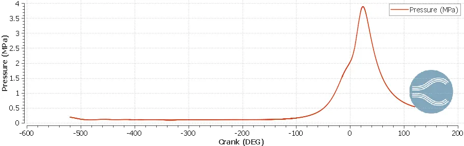
Pressure:
Pressure increase when the combustion is taking place the max pressure attained whne the combustion is taking place is mearly 3.9 MPa
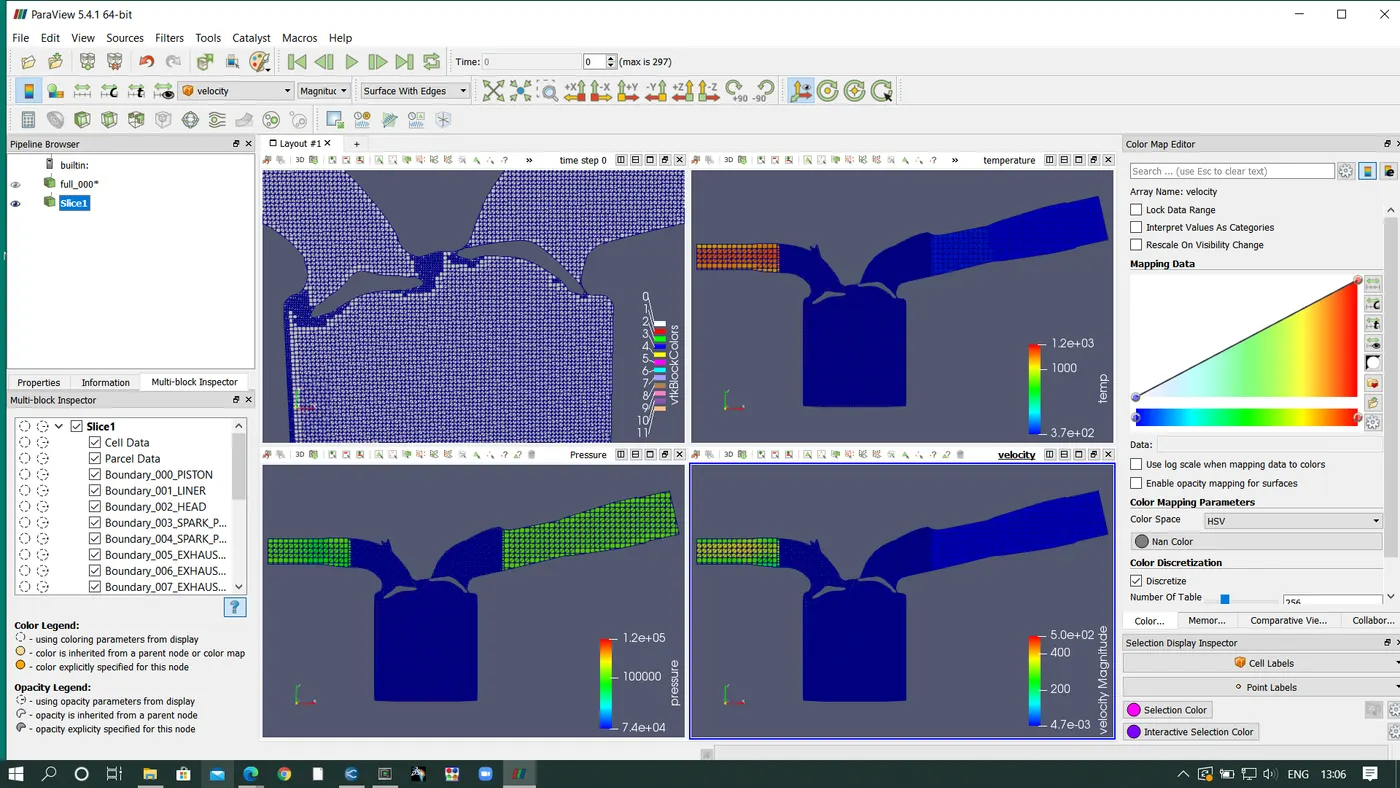
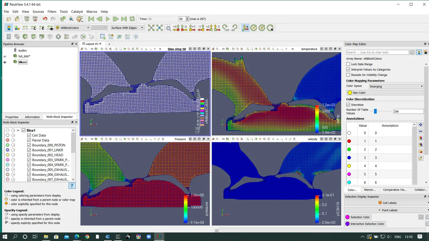
Post processing:
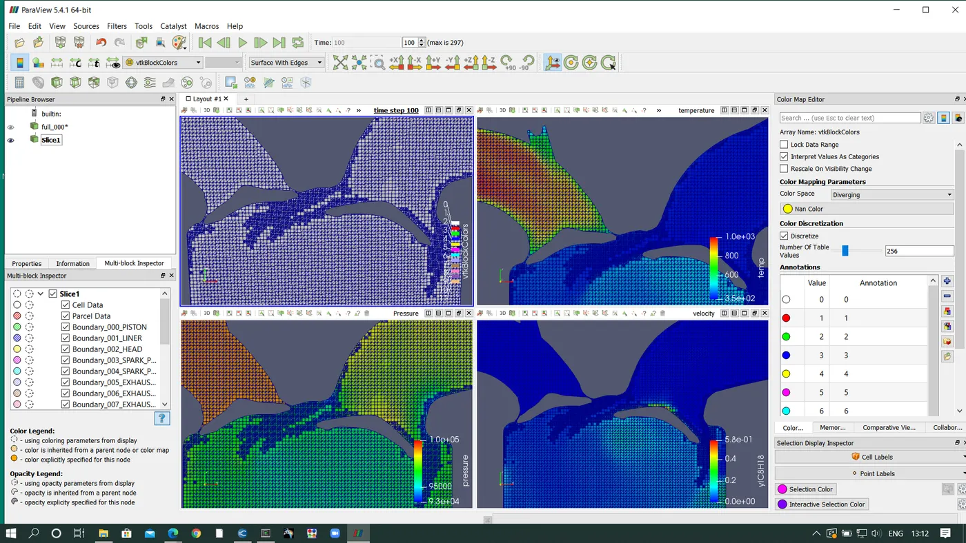
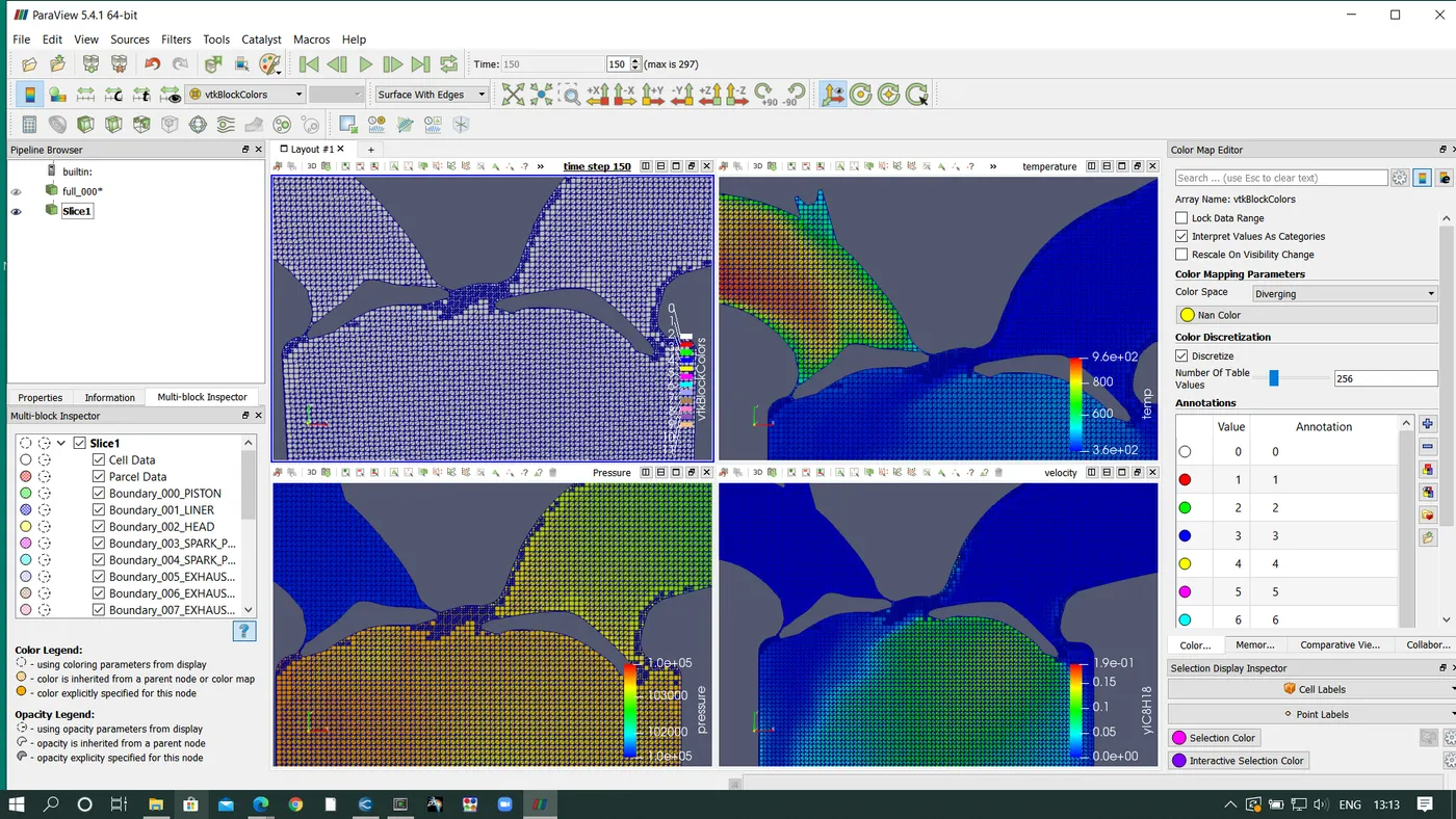
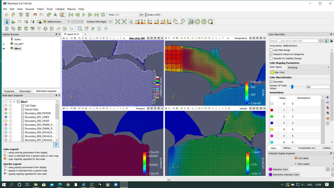
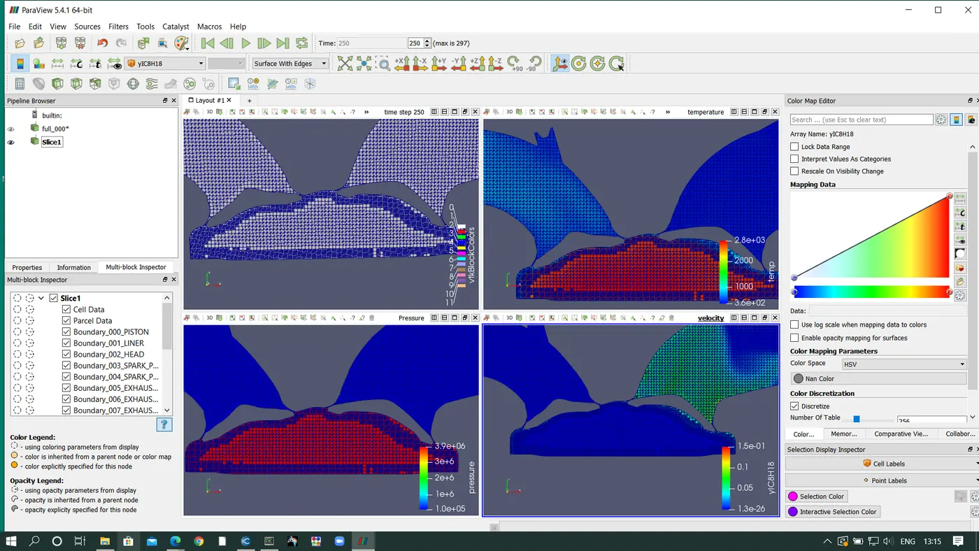
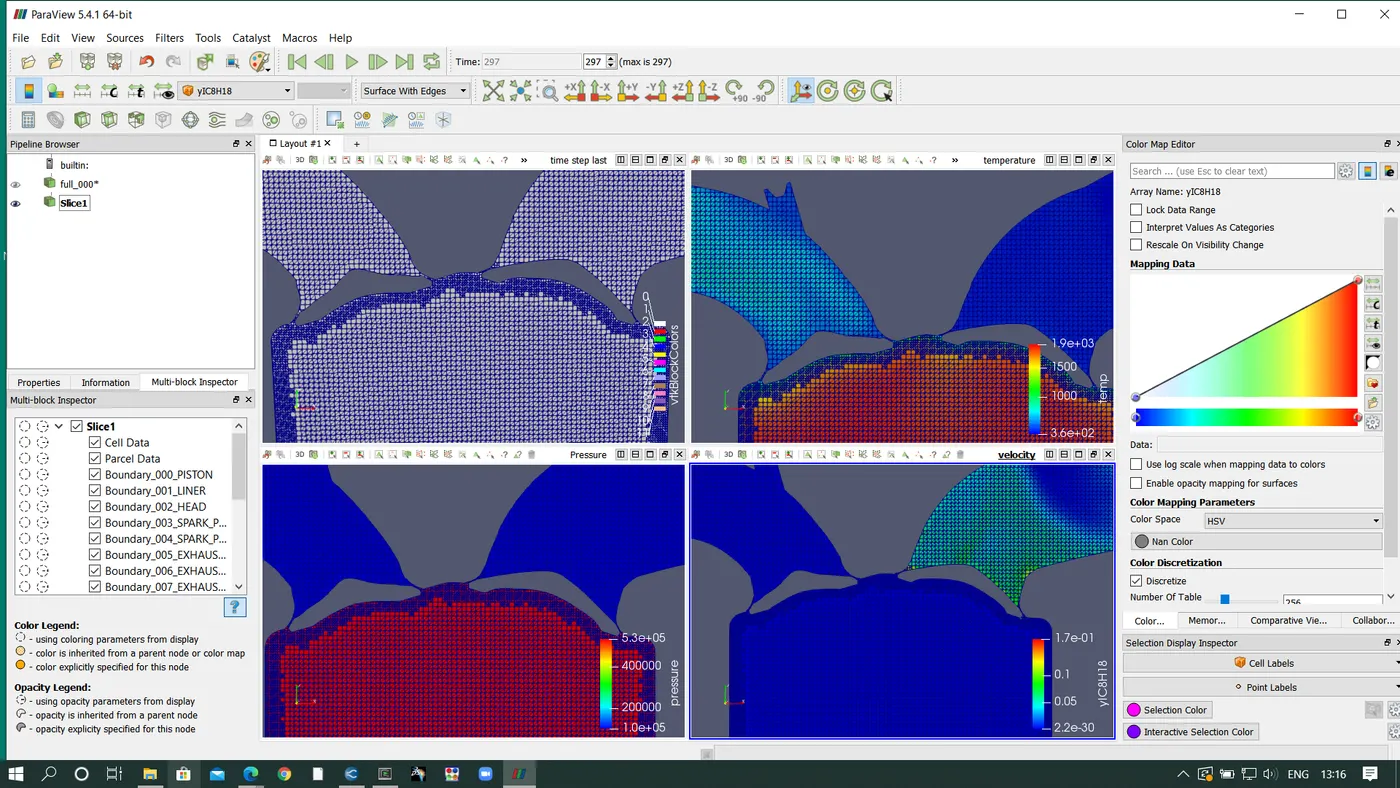
Meah Generation at different time steps with temperature, pressure and IC8H18
1.
What is compression Ratio?
compression ratio = Vmax/Vmin
vt = 0.000574193
vc = 5.76567e-5
CR = 9.959
2.
Why do we need a wall heat transfer model? Why can't we predict the wall temperature from the CFD simulation?
Heat transfer in IC engines has direct effect on engine performance. In this simulation the setup of streamID's for the solid boundary is diasabled Navier stokes equation, turbulence model and species transport equation are used to solve governing equation. Therefore making use of energy equation for solving sollid boundary.
A spark is responsible for ignition of fuel and air when compressed inside the cylinder which emits the flame spreads through the cylinder. After a few times the falme gets vanished as soon as it makes contact with the liner which tells the heat is transfered to the solid boundary and inside the cylinder because of turbulence some parameters are affected.
3.
Calculating Combustion Efficiency:
The combustion efficiency is defined as the ratio between the energy released by burnt fuel and the energy content of the fuel mass
output power = 1241.06J
Energy content of fuel = mass of fuel induced per cycle*Fuel LHV
Fuel LHV of ICO Octane is 44.651 MJ/Kg
mass induced = 3e-5
Combustion Efficiency = 1241.06/(44.651e6*3e-5)
0.9317 = 93.17%
4.
Power output:
Duration = 240degress
1 rotation = 360deg
RPS of engine = 50
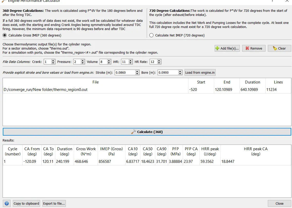
work done is 468.646n-m
RPM = 3000
power = work done/time
Degrees per second = 50*360 = 18000
Time per degree = 60/(360*3000)
Time per 240 deg = (240.2*60)/(360*3000)
= 0.01333
power = 468.646/0.01333
P = 35236.541 watt
Power= 2*pi*N*T/60
35236.54 = (2*pi*3000*T)/60
T = 112.218 N-m
5.
Significance of CA10 CA 50 and CA 90 is crank angle where the combustion is taking place.
CA 10 Crank angle combustion at 10deg 6.83717 means 10% combustion occurs.
CA 50 Crank angle combustion at 50deg 18.4623 means 50% combustion occurs.
CA 90 Crank angle combustion at 90deg 31.701 means 90% combustion occurs.
Animations:
Mesh generation:
Temperature:
Conclusion:
Full Hydro simulation setup of PFI engine was done using converge studio and simulation using cygwin and post processing using paraview.
From the simulation the power output is calculated and the power,toruque combustion efficiency and compression ratio produced by the engine is:
Power Output = 35236.541 watt
Torque = 112.218 n-m
Combustion Efficiency= 93.117%
Compression Ratio = 9.959