Project: Port Fuel Injected SI Engine Simulation
Objective: To simulate the Full Hydro Case Setup of a Port Fuel Injection Engine using Converge CFD and with the inputs provided in the challenge description, find out the following
1. What is the compression ratio of this engine?
2. Why do we need a wall heat transfer model? Why can't we predict the wall temperature from the CFD simulation?
3. Calculate the combustion efficiency of this engine
4. use the engine performance calculator, to determine the power and torque for this engine.
5. What is the significance of CA10, CA50 and CA90?
Valve motion in PFI Engine ---->
Case Setup:
The following parameters are required to run a full hydrodynamic simulation -
- Engine Geometry
- Materials definition (Gas species involved in combustion)
- Boundaries
- Simulation parameters
- Initial conditions (Region definition)
- Events
- Spray Modeling
- Combustion modeling
- Turbulence modeling
- Mesh definition
After running the no-hydro setup to validate the set parameters for full-hydro setup and boundary flagging, the full-hydro simulation case is required to be setup.
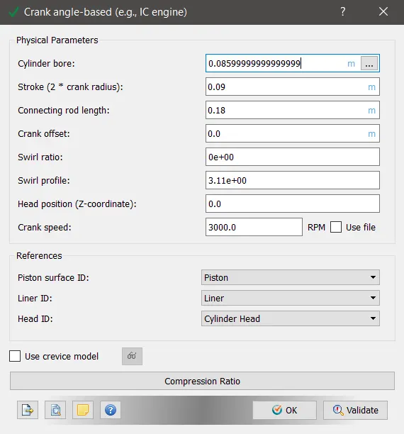
The engine geometry parameters for a PFI engine are setup as shown below:
Engine Geometry:
Materials:
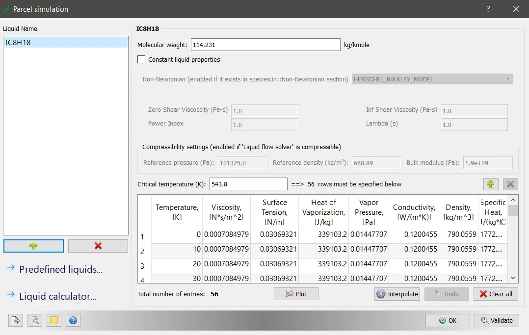
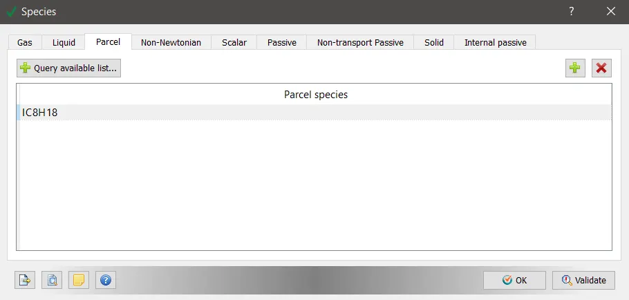
In the full-hydro setup of the IC engine simulation, it is required to specify which fuel is injected into the cylinder and what type of reactions are taking place inside the combustion chamber. In order to simulate the reaction happening inside the combustion chamber , the species participating inside the combusion chamber need to be analyzed and also the rate of reaction needs to be controlled. The parcel simulation option allows to control the flow pattern or to be more specific ensures that flow parcels are maintained at specific temperatures and physical properties inside the combustion chamber.
IC8H18 (Iso-octane): The IC8H18 fuel is close to Gasoline in physical properties. Hence, the IC8H18 fuel is chosen as 'parcel species' and hence more thermodynamic data will require more species to be included inside the reaction mechanism whose data is available in the file 'therm.dat'
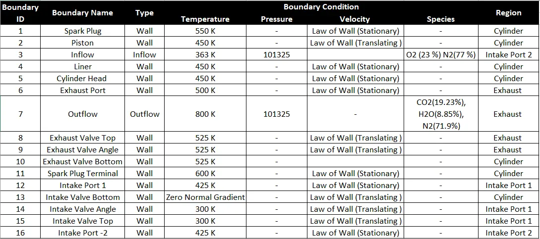
Boundary Conditions:
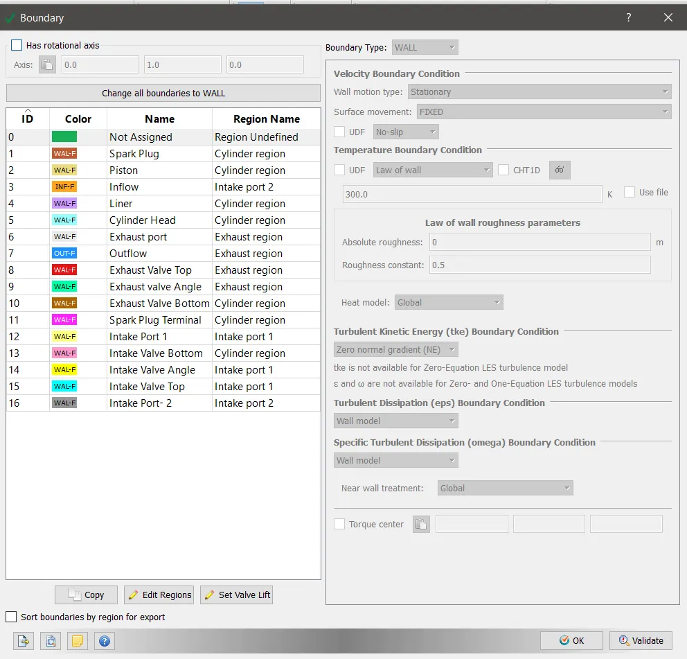
The boundary conditions for the given simulation are setup with the following important properties such as temperature, pressure,velocity and species with specific regions assigned to each boundary.
Simulation parameters:
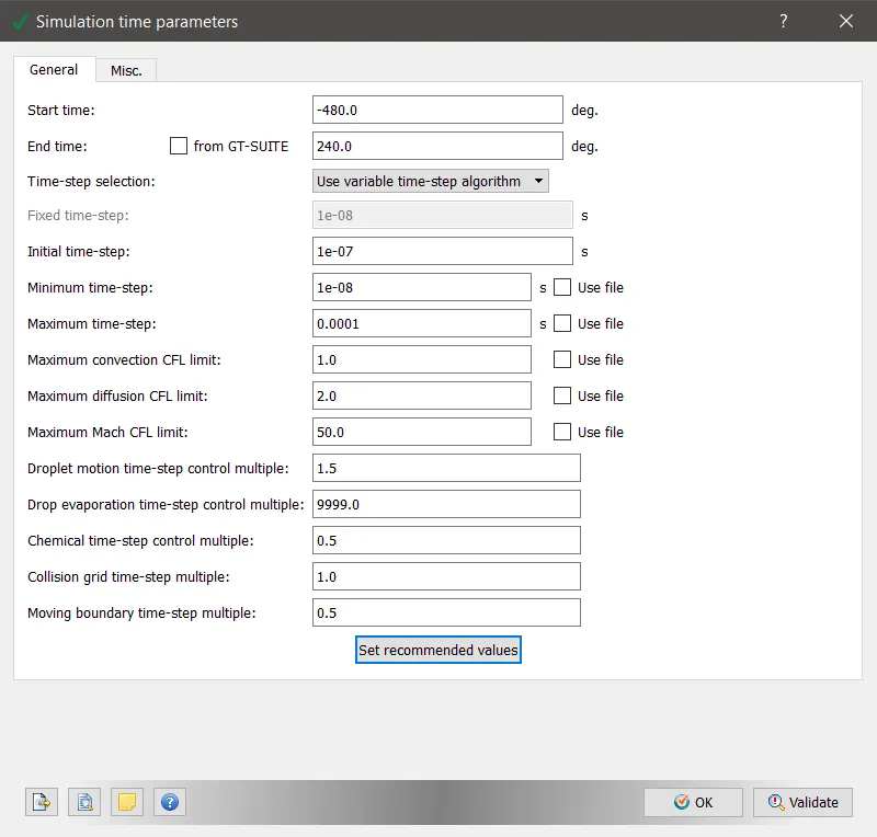
The solver parameters are taken as default values.
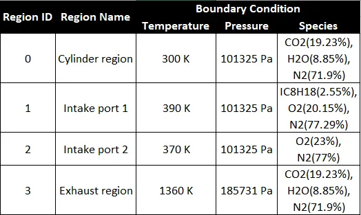
Volumetric regions:
The PFI geometry is divided into 4 distinct regions with each bounadry bifurcated and assigned to a specific region. Since, the temperature inside a combustion chamber is higher than the intake port same as that of the temperature of the species in the exhaust are at a higher temperature than the cylinder we need to assign different regions with different temperature and pressure conditions.
Events:
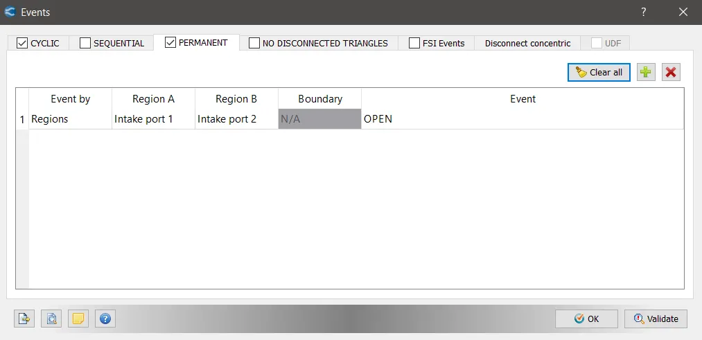
Converge does not allow two regions to intersect unless a timing event is enabled using the events section. For a flow event happening through different boundaries and ensure a continuous simulation the 'Events' option is used.
The intake and exhuast valve lifts are executed after providing both intake and exhaust valve lift profiles.
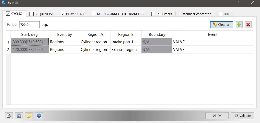
The intake port is divided into two regions since in the intake port 1 region the fuel is sprayed while in the intake port region 2 air is present. Though the intake port is divided into two parts, there is no movement of surfaces during this event. Hence, the event is an 'Open event'
Physical Models:
In order to capture the flow physics accurately inside the IC engine, following models have been incorporated accordingly,
- Spray Modeling
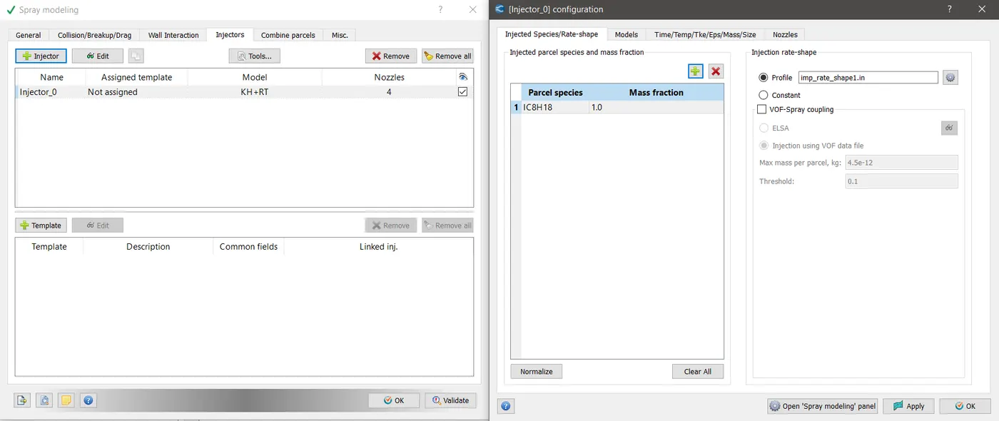
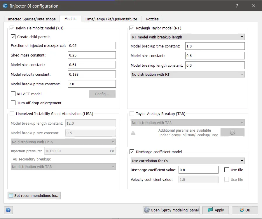
The Kelvin - Helmholtz model (KH) and Rayleigh- Taylor model (RT) are common models used for injectors and are studied from the literature.
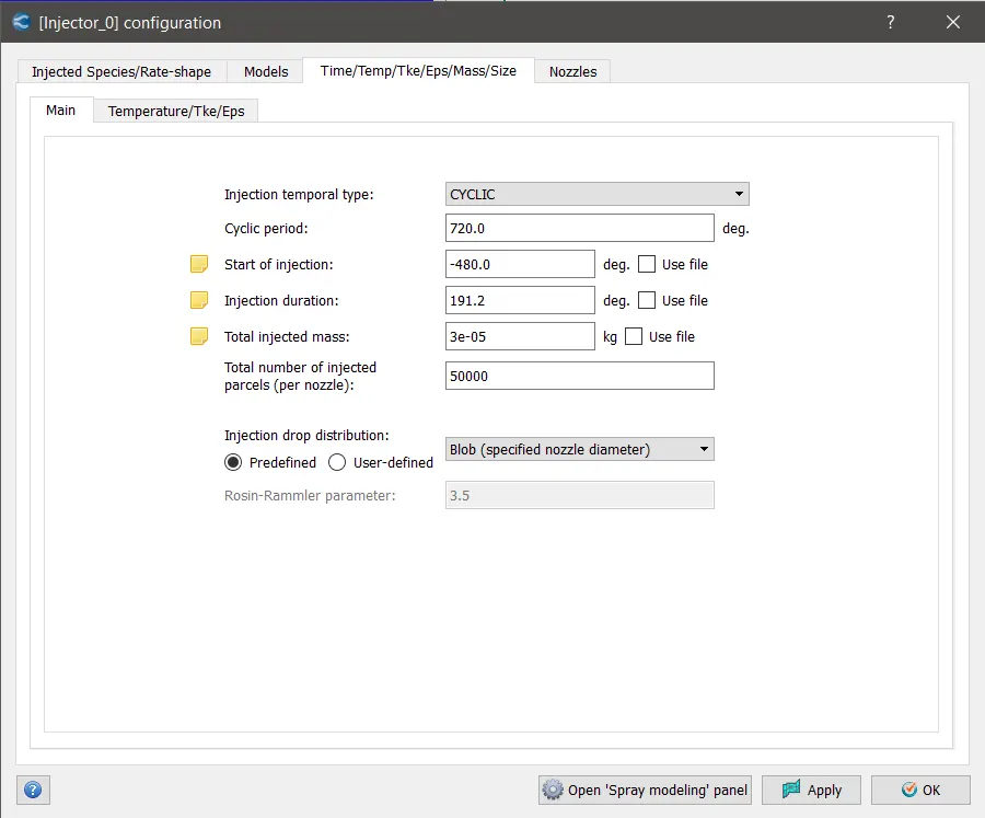
The injection period and injected mass values are set as follows:
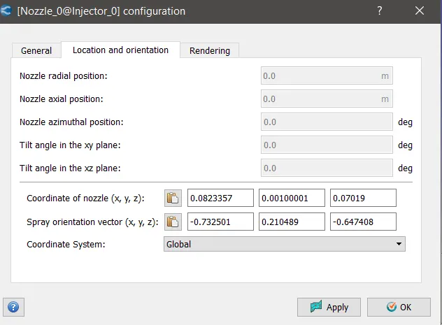
The co-ordinates for injector location and the spray orientation vector are required to be specified as follows:
2. Combustion modeling
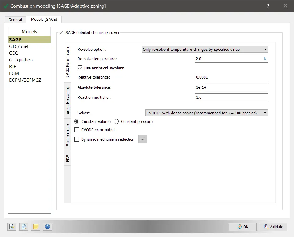
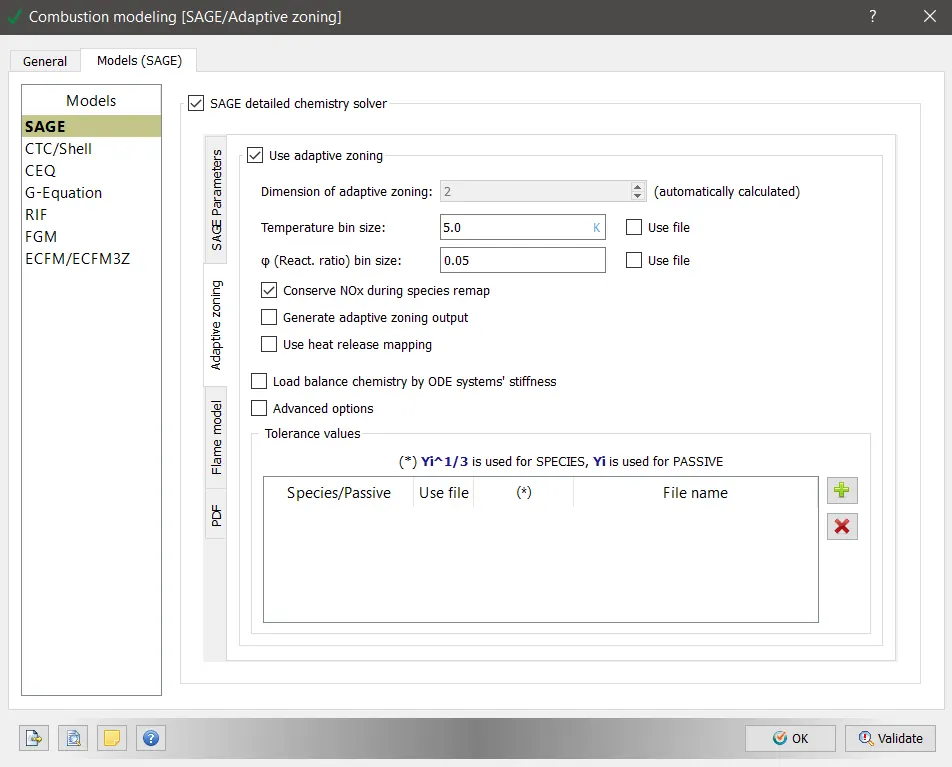
The 'SAGE' model of combustion is used typically as a combustion model.
Converge’s SAGE detailed chemistry solver uses local conditions to calculate reaction rates based on the principles of chemical kinetics. This solver is fully coupled to the flow solver, but the chemistry and flow solvers parallelize independently of one another, which speeds up the simulation. With the appropriate mechanism, the SAGE solver can predict a wide range of cases (e.g., a variety of fuels [premixed, non-premixed, partially premixed, multiple fuels], emissions modeling, and unique phenomena such as end-gas auto-ignition). With its accuracy and robustness, Converge can perform predictive modeling instead of merely confirming experimental results.
Source:https://convergecfd.com/applications/internal-combustion-engines
3. Turbulence modeling:
The default 'RANS model' for turbulence is used for the following simulation.

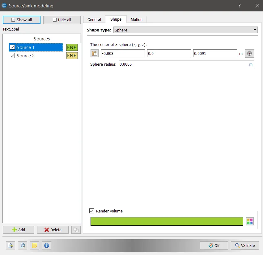
4. Source/sink modeling:
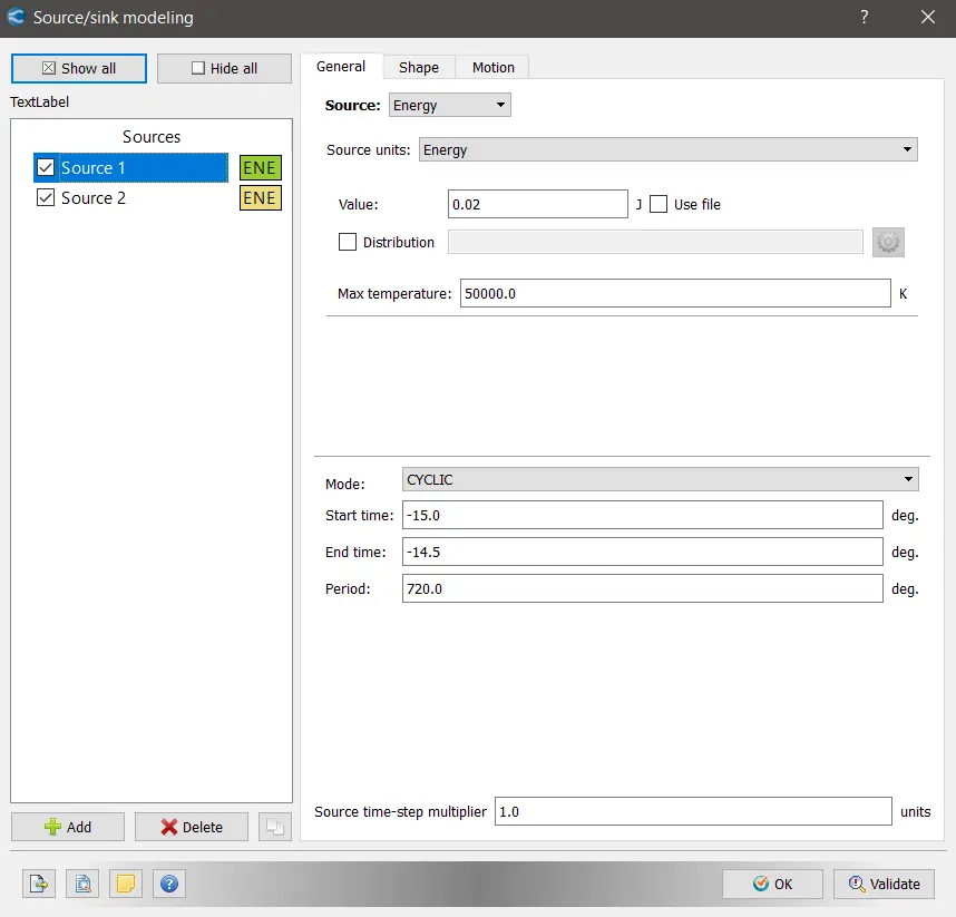
The source / sink modeling option is used to define extra source of energy,momentum,turbulence and species.
Grid Control:
The base grid defined for the following simulation is 4 mm.
In addition to base grid , 'Adaptive Mesh Refinement' option is enabled to analyze the specific parts of the combustion more closely.
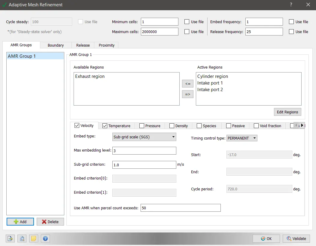
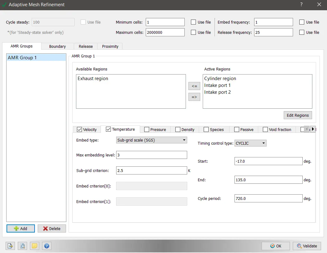
Both temperature and velocity base grid refinement option is enabled in the cylinder and intake port regions.
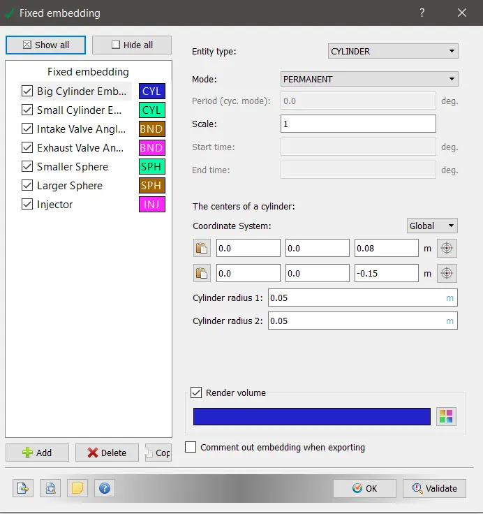
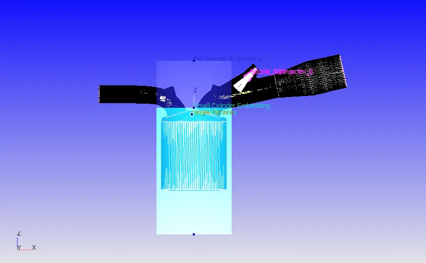
Fixed Embedding:
The fixed embedding option allows to capture accurate information at particular locations.
Important Questions:
- What is the compression ratio of this engine?
Compression Ratio of the Engine --->
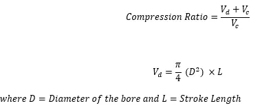
The compression ratio of the engine is the ratio of the volume swept by the cylinder to the clearance volume. The swept volume is the total volume displaced in addition to the clearance volume.
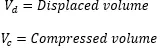
The swept volume is given by,

where,
Hence , the compression ratio is given by
The Vc volume is directly measured and can obtained from the following graph,
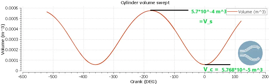
The calculation for compression ratio is as follows,

2. Why do we need a wall heat transfer model? Why can't we predict the wall temperature from the CFD simulation?
The heat transfer inside a combustion chamber occurs through the cylinder walls through convection as well as conduction. The heat transfer mechanism influences the combustion efficiency , emissions characteristic of an engine alongwith the mechanical reliability of the engine. A correct estimation of the heat fluxes is necessary for optimum engine operation. An accurate estimation can hence be achieved using a heat transfer model which can predict the wall temperatures precisely throughout the combustion cycle.
The fluid temperature near the wall is higher than the wall temperature. Hence, the combustion process cannot be considered isothermal.Hence, models accounting for the variation in thermal properties of the fluid were developed. To solve the Navier Stokes equation the bodies over which the fluid is flowing are called as 'Voids' or 'Holes'. The body surfaces hence become a boundary and to solve the NS equations it is necessary to specify the boundary conditions. Infact, the wall temperatures are itself the boundary conditions which are required to solve the equations.
3. Calculate the combustion efficiency of this engine.
Combustion efficiency of an engine is the ratio of power output of an engine to the heat released by the fuel burnt.
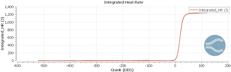
Lower heating value of gasoline = 43.4 MJ/kg
Mass inducted into the cyinder per cycle= 3*10^-5 kg

4. Using the engine performance calculator, to determine the power and torque for this engine.
The engine performance calculator tool from the 'Line Plotting' module of 'Converge CFD' is used to calculate the net work done by the engine.
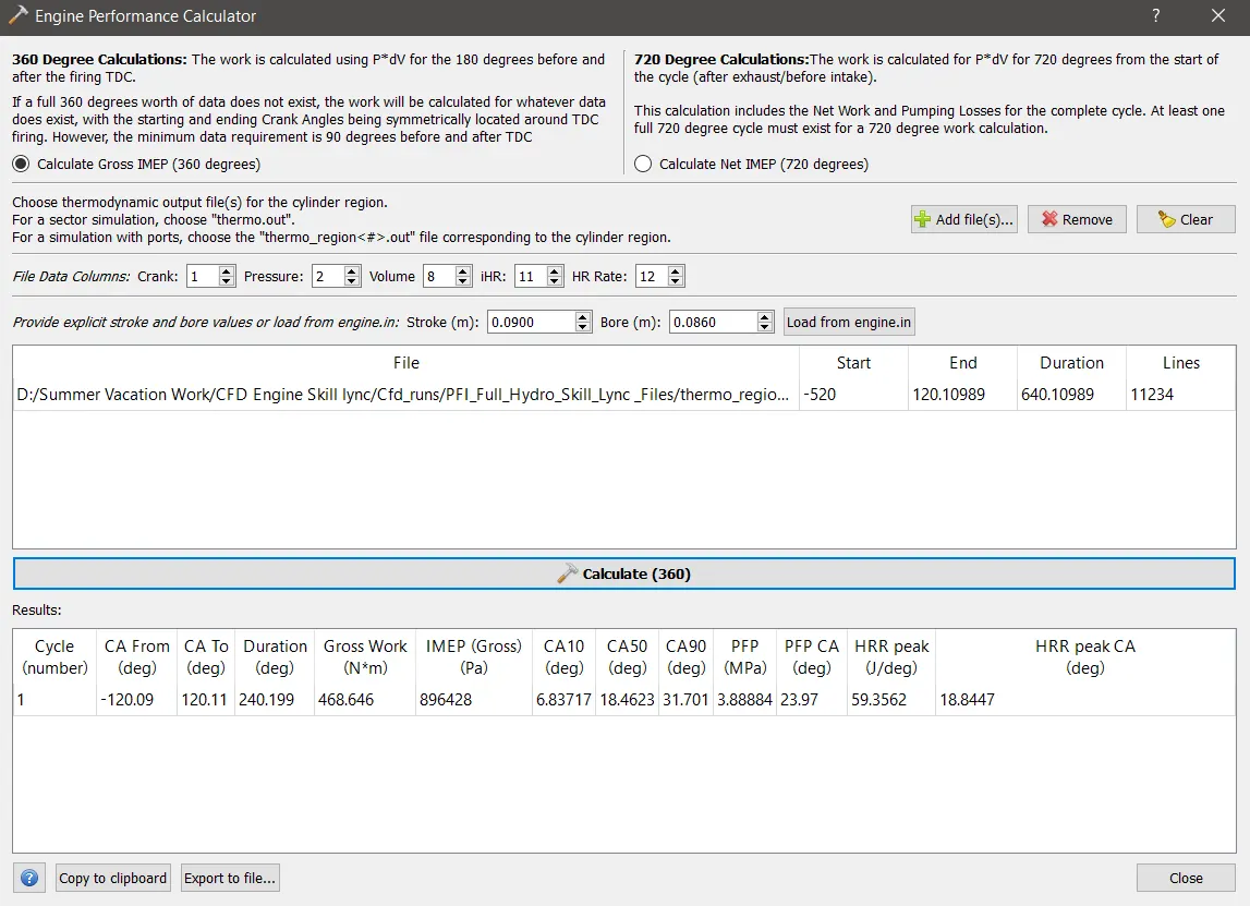
The gross work done by the engine is 468.64 Nm for a duration of 240.199 degrees.
However, the power produced by the engine is different than the net work done and hence needs to be calculated from the values obtained from the calculator.
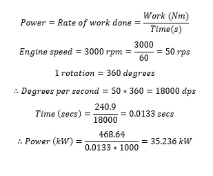
The engine torque is determined from the power calculated from the above equation,

5. What is the significance of ca10, ca50 and ca90?
Mass fraction burned (MFB) in each individual engine cycle is a normalized quantity with a
scale of 0 to 1, describing the process of chemical energy release as a function of crank angle.
The determination of MBF is commonly based on burn rate analysis – a procedure developed by
Rassweiler and Withrow . It is still widely used though its evident approximating character because of its relative simplicity and computational efficiency.
The crank position where MFB becomes 10% is called CA10 , while at 90 % MFB and 50 % MFB it is CA90 and CA50 respectively.
The difference between CA10 and CA90 is called 'Combustion duration' or 'Rapid Burning Phase' while from the period between 0 degree and CA10 is called ' Flame Development Phase' of burning.
Results:
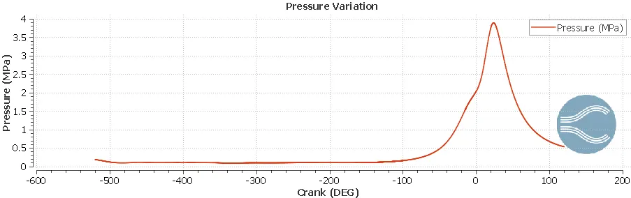
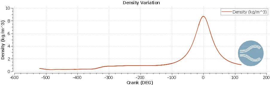
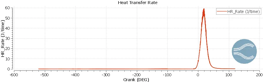
P-V Diagram:
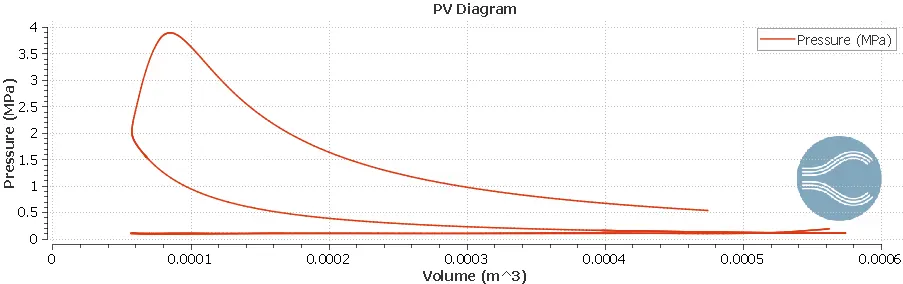
The PV Diagram resembles to that of Otto cycle. The PV diagram is distortred since some data is missing.
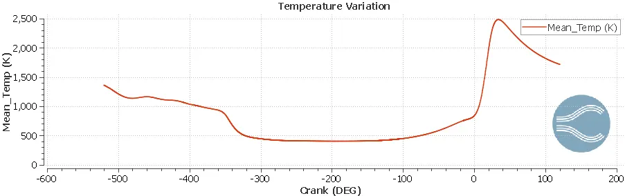
Temperature variation over period of time ---->
Pressure variation over period of time ---->