Week 10: Project 1 - FULL HYDRO case set up (PFI)
ICE) is a heat engine in which the combustion of a fuel occurs with an oxidizer (usually air) in a combustion chamber that is an integral part of the working fluid flow circuit. In an internal combustion engine, the expansion of the high-temperature and high-pressure gases produced by combustion applies direct force to some component of the engine.
The term internal combustion engine usually refers to an engine in which combustion is intermitten, such as the more familiar 4 stroke and 2 stroke piston engines, along with variants, such as the 6 stroke piston engine and the wankel rotary engine.
Typically an ICE is fed with fossil fuels like natural gas or petroleum products such as gasoline, Diesel and Fuel oil. There is a growing usage of renewable Fuels like biodiesel for CI (compression ignition) engines and bioethanol or methanol for SI (spark ignition) engines.
1.What is compression ratio of the engine ?
Compression ratio:
In a piston engine, the static compression ratio is the ratio between the volume of the cylinder and combustion chamber when the piston is at the bottom of its stroke, and the volume of the combustion chamber when the piston is at the top of its stroke.It is therefore calculated by the formula.
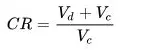
 displacement volume. This is the volume inside the cylinder displaced by the piston from the beginning of the compression stroke to the end of the stroke
 clearance volume. This is the volume of the space in the cylinder left at the end of the compression stroke.
it can estimated by cylinder formula which is = area of the cylinder *stroke length
where, Area of the cylinder = Pi*R^2 ,r is the radius of the cylinder bore,Stroke length=s
Because of the complex shape of Vc it is usually measured directly. This is often done by filling the cylinder with liquid and then measuring the volume of the used liquid.
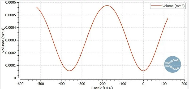
Vc=5.75877e-05
vd=5.74212e-4
CR=(5.75877e-05+5.74212e-4)/(5.75877e-05);
CR=10.971
2.Why do we need a wall heat transfer model? Why can't we predict the wall temperature from the CFD simulation?
Heat losses should be minimized to get maximum power output In the combustion stroke to obtain maximum power output there should be no heat losses during this stroke but in reality there would be heat loss in the system which would be transfered to the the cylinder head so heat transfer model should be adopted to accomplish efficient power output
For this PFI engine simulation it takes lot of time to compute the case as it involves a complex geometry and process.If we want to capture the heat transfer-especially convection of heat from fluid to solid surface ,energy equations should be solved. This increases the time of simulation for rr radiation of heat from the solid surface to atmosphere,an external mesh is to be made to depict the external atmosphere and to solve the energy equation which increases the cell count.It makes the simulation to run forever.Hence we use conjugate heat transfer model where solid part is solved in a steady state using super-cycling option and the fluid part is solved in the transient case
For simulating complex geometries like IC engine it takes alot of time to compute the fluid part itself iin transient case along with the combustion and reaction processes.So it becomes difficult to predict the wall temperature from the CFD simulationWall heat transfer models are used to approximate this case.Basically all physical models used in CFD simulation uses some approximation to minimize computational time.Wall heat transfer models are used if are focused only on heat transfer giving less importance to fluid motion and reaction.For efficient operation of the engine the walls should be maintained at a certain temperature.This is achieved by pumping coolant to take away the excess heat from cylinder wall.
3. Calculate the combustion efficiency of this engine
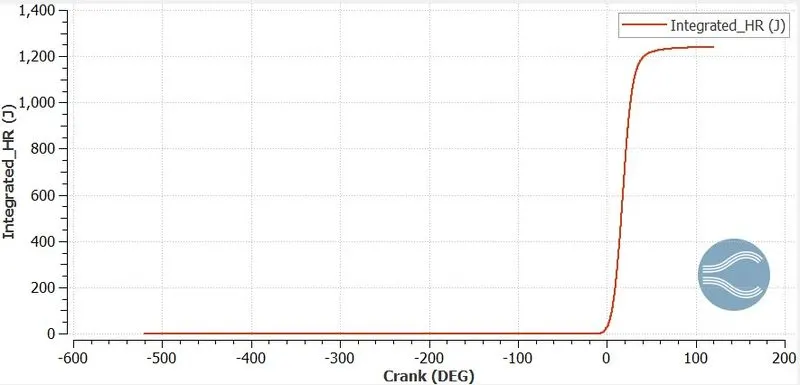
Efficiency= IHR/(m*CV)
Maximum value of IHR=1241Joules
Calorific value of iso-octane at standard condition=47.78e6(J/kg)
Total mass of fuel injected in 720 degrees of crank angle=3e-05kg
efficiency=1241/(47.78e6*3e-5)= 0.865773=86.577%
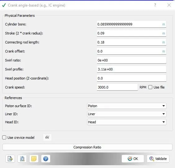
Engine Geometric Parameters
- Bore =0.086 m
- Stroke = 0.09 m
- Connecting rod length = 0.18 m
- RPM = 3000
4.To determine the power and torque for this Engine?
Go to CONVERGE ---> PLOTS --> Tools ----> Engine Calculations ---> Engine Performance
To calculate power we can use the formula; Power = Work/sec
From performance calculator we can take;
Work = 468.646 Nm
Start time = -120.09 deg
End time = 120.11 deg
Total duration = 240.199 deg
Total rotation per minute RPM = 3000 (Given)
Rotation per second = 3000/60 = 50.
Total degree per second = 50*360 = 18000
Time in sec = 240.199/18000 = 0.01334 sec.
Power = 468.646/0.01334
Power = 35130.88 Kj = 35.13 KW
Power P=(2*pi*N*T)/(60)
T=(P*60)/(2*pi*N);
T=(35120.35)*(60)/(2*pi*3000)
Torque =111.8489 Nm
5.Significance of CA10,CA50 and CA90 :
It is the crank angle at 10%,50% and 90% fuel combusted.From these value we can see that the actual change of crank angle with respect to fuel combustion
The physical significance of CA10 is that it is used to identify the start of the ignition, whereas the CA50 indicates the end of the premixed combustion and start of diffusion combustion of fuel used in engine,Ca10-90 determines comustion duration and at ca90 the burning of unburnt fuel is done by propogating flame.If Ca90 value is large ,the crank angles taken increases and the exhaust stroke tends to push the premature combustion products.
Mainly, Ca10, ca50 and ca90 refers to the crank angle at which percentage heat release is 10%, 50% and 90% of the max heat release.
The parameters which are necessarily required in order to run a complete full hydrodynamic simulation of PFI are given below:
1. Engine Geometric Parameter
2. Run Parameters
3. Simulation time parameter
4. Boundary condition
5. Initial condition
6. Injection parameter
7. Nozzle Position
8. Spark Ignition parameters.
CASE SETUP :
We already have successfully done surface preparation and Boundary flagging of PFI geometry.
Go to Materials to select PARCEL SIMULATION
Click on Parcel simulation and Go to Predefined liquids here im going to select the 'IC8H18_Isooctane
So the question is why i am using this ? isooctane has physical properties that are very close to Gasoline Fuel. so the thing is based upon fuel we need to use the right species.
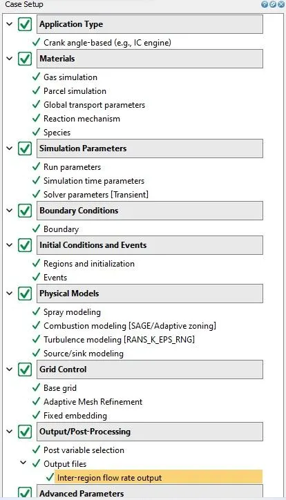
Application Type :
Crank angel based IC engine
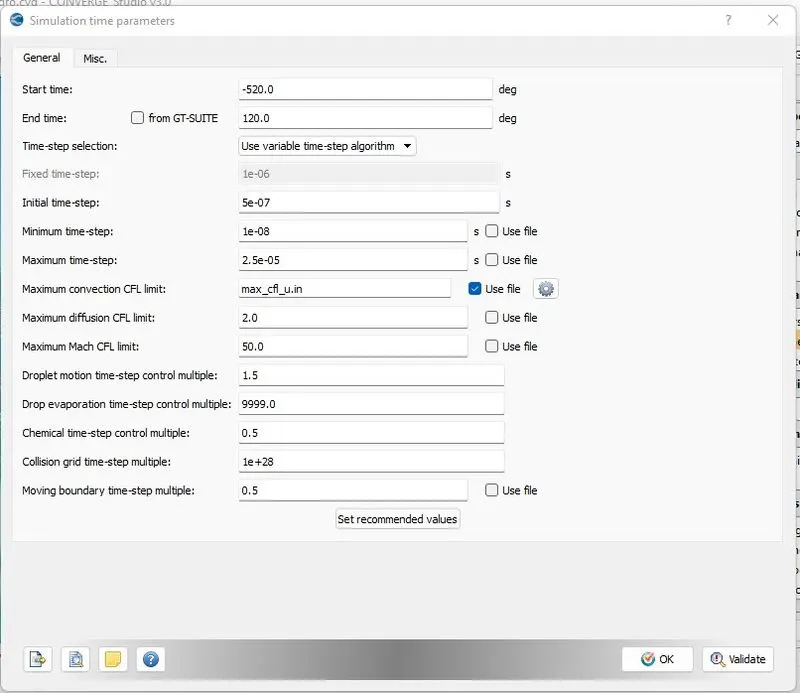
Simulation time parameters
- Start time : -520 deg
- end time : 120 deg
Simulation Parameters :
Bounday Conditioons :
- Piston temperature - 450K
- Liner temperature - 450K
- Head temperature - 450K
- Spark Plug temperature - 550K
- Spark Plug electrode temperature - 600K
- Exhaust ports temperature - 500K
- Exhaut outflow - 1 bar
- Exhaust outlflow temperature - 800k
- Exhaust species concentration - Calculate the stoichiometric condition
- Exhaust valve top temperature - 525K
- Exhaust valve angle temperature - 525K
- Exhaust valve bottom temeprature - 525K
- Intake port - 1 temperature 425K
- Intake port - 2 temperature 425K
- Inflow pressure - 1 bar total pressure
- Inflow temperature - 363K
- Inflow species - Air
- Intake valve top temperature - 480K
- Intake valve angle temperature - 480K
- Intake valve bottom temeprature - 480K
Initial Conditions and events :
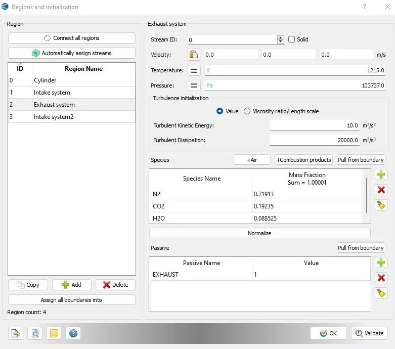
Region and initialization :
Entire geometry is divided into the volumetric regions which converted into different boundaries
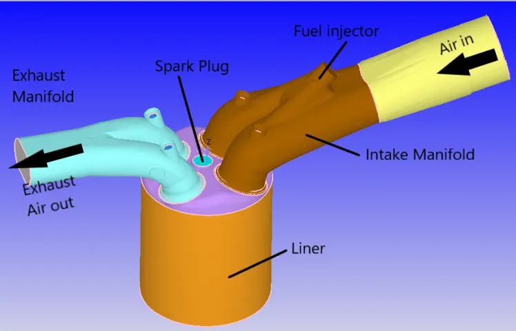
Initialization of different regions
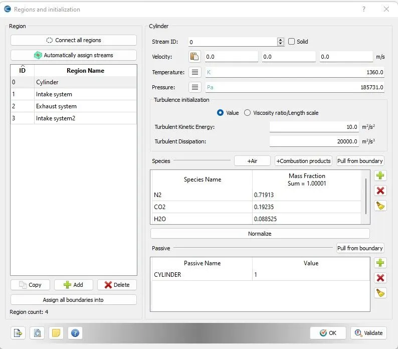
Initial conditions
- Cylinder
- Pressure - 1.85731 bar = 185731 Pa
- Temperature - 1360K
- Stoichiometric composition
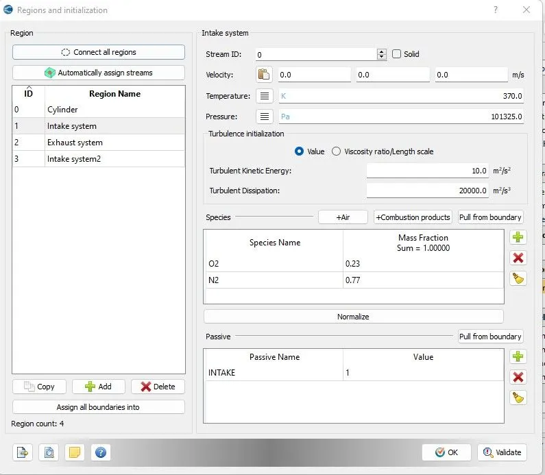
- Intake port - (away from combustion chamber)
- Air
- Temperature - 370K
- Pressure - 1 bar
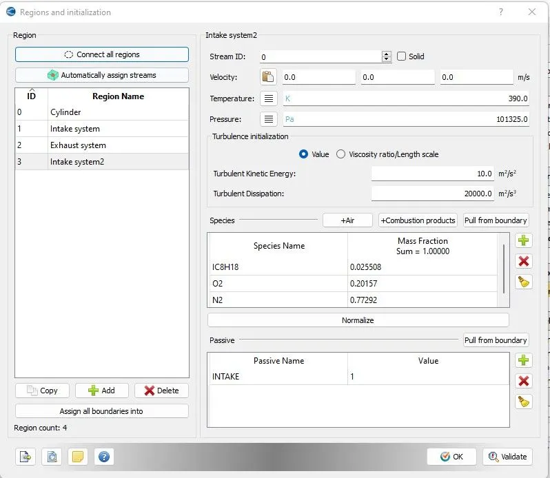
- Intake port - 2 (closer to combustion chamber)
- ic8h18 - 0.025508
- o2 - 0.20157
- n2 - 0.77292
- Temperature - 390k
- pressure - 1 bar
Events :
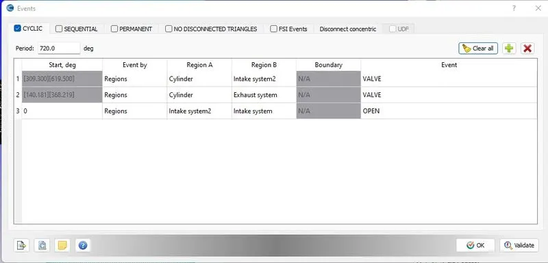
opening and closing of intake valve plays a key role in the IC engine to simulate the valves events are used.
Physical models :-
Spray modelling :
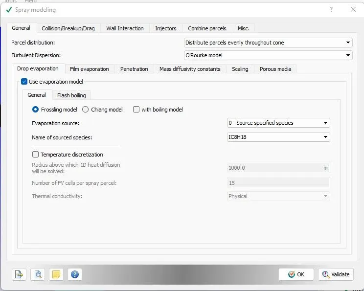
In general,
Select Parcel_distribution as ----> 'Distribute parcels evenly throughout cone' --- It is experimentally found that spray of gasoline fuel is distributed evenly throughout the cone .
Select Turbulent Dispersion as --- > O'Rourke model -- This is actually better describes the spray of gasoline fuel.
Evaporation model - Tells us rate at which parcels going to evaporate.
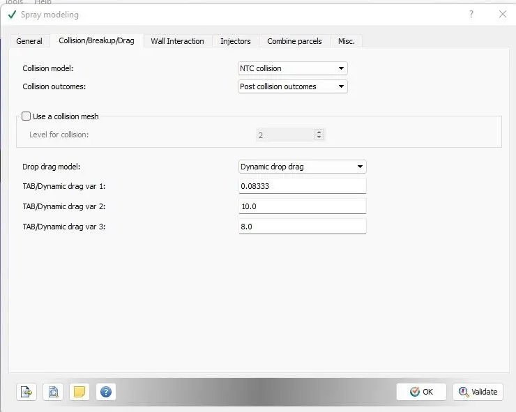
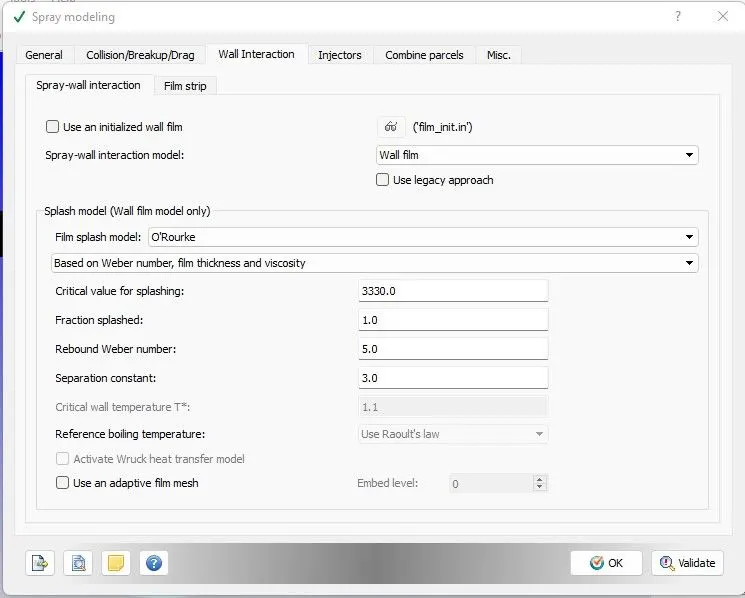
In wall interaction :
Select wall film because we want wall film to be formed.
In Injectors :
Parcel species - IC8H18
Import injection 'RateShape' prepared file.
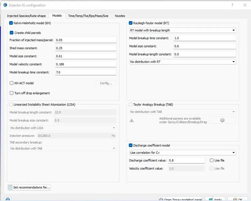
Select KH + RT models :
Injection mass :
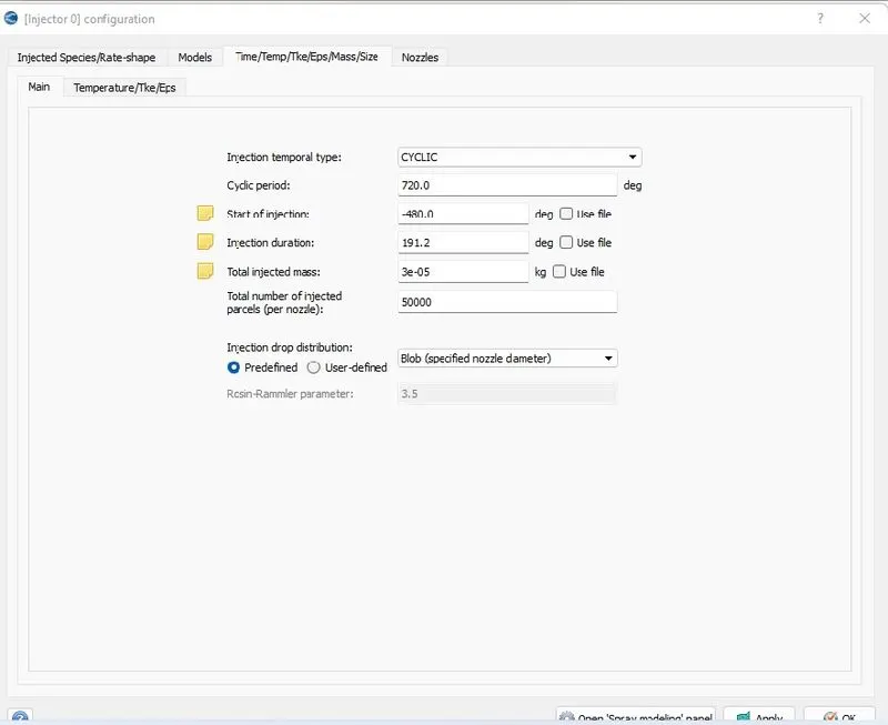
Injection Parameters
- Fuel flow rate = 7.5e-4 Kg/second
- Injection start time = -480.0
- Injection duration = 191.2
- Fuel temperature = 330K
so by calculating for 3000 rpm of engine and 720 degree
Fuel mass injected per cycle = 3e-5kg/cycle
Nozzle positions
Nozzle diameter = 250 micro-meter
Circular injection radius = Nozzle radius
Spray cone angle = 10
- Nozzle 0
- center 0.0823357 0.00100001 0.07019
- Align Vector -0.732501 0.210489 -0.647408
- Nozzle 1
- center 0.0823357 -0.00099999 0.07019
- Align Vector -0.732501 -0.210489 -0.647408
- Nozzle 2
- center 0.0823357 -0.0004 0.07019
- Align Vector -0.5 -0.2 -0.647408
- Nozzle 3
- center 0.0823357 0.0003 0.07019
- Align Vector -0.5 0.2 -0.647408
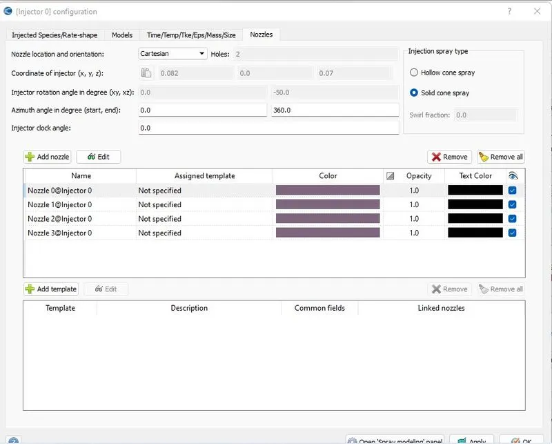
For particular nozzle, set diameter, location and orientation provided.
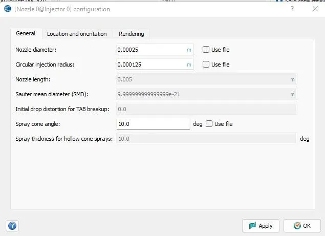
and vice_versa for injector 1,2 and 3
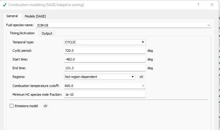
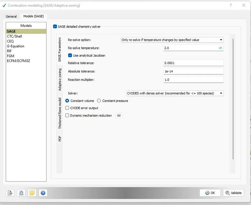
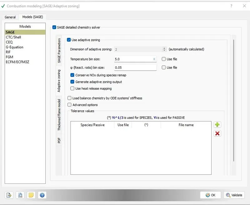
Combustion Modeling :
Set the start time for combustion just some degree before fuel injection is happening. so the solver would be ready till the time of injection.
Turbulence Modeling :
RNG K-epsilon model
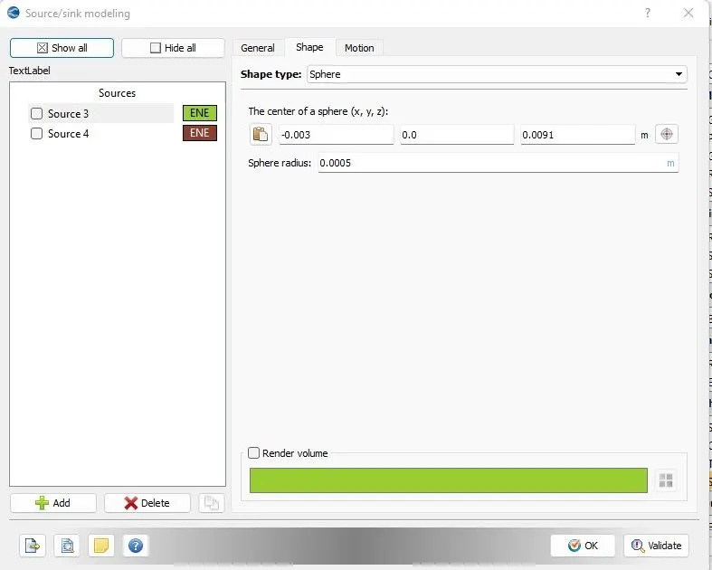
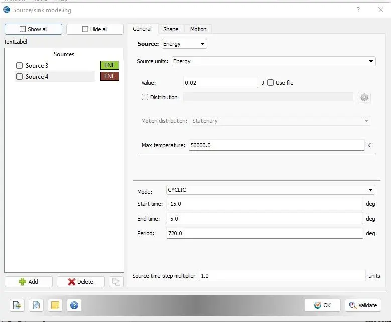
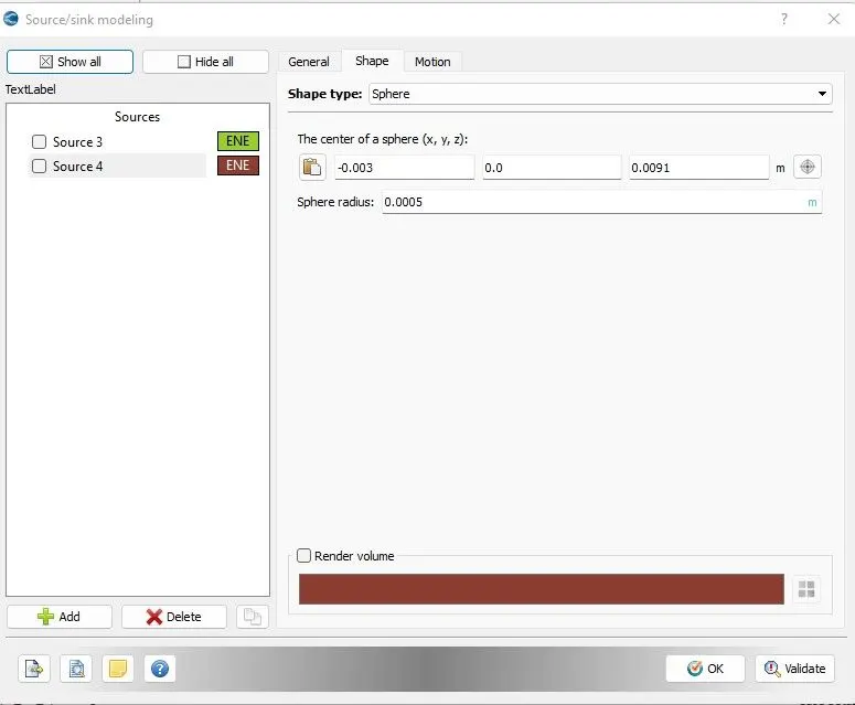
Spark Ignition Parameters
- Start of spark = -15 degree
- Spark location = -0.003 0 0.0091
- Spark radius = 0.0005m
Source/Sink Modeling :
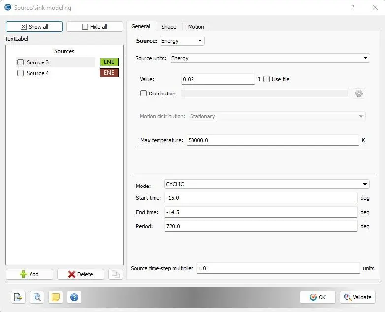
As it is a PFI engine using iso-octane (whose properties resemble gasoline ) . It need a spark to ignite fuel-air compressed mixture.
so an energy source is provided.
For -15 to -14.5 crank angle total 40MJ of energy given to initiate combustion then from -15 to 5 degree only 20MJ energy given to sustain combustion already initiated.
Grid Control :
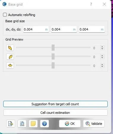
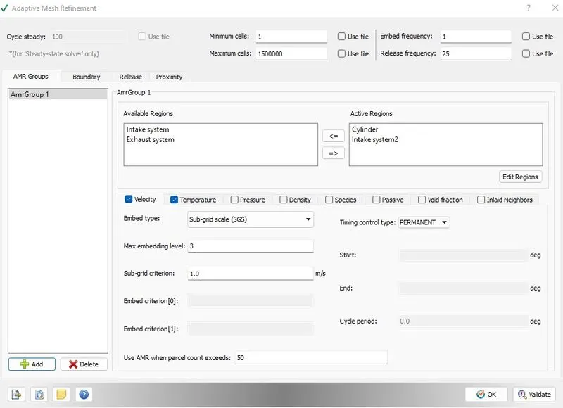
Enable - 1) Adaptive mesh refinement
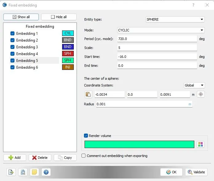
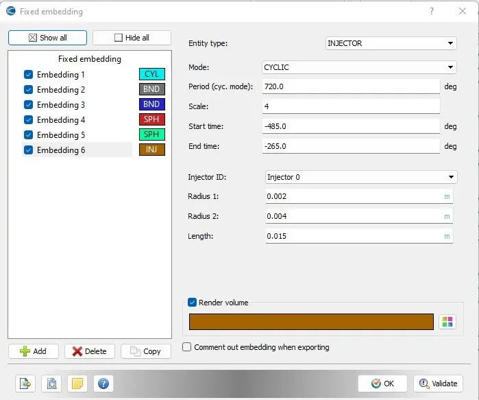
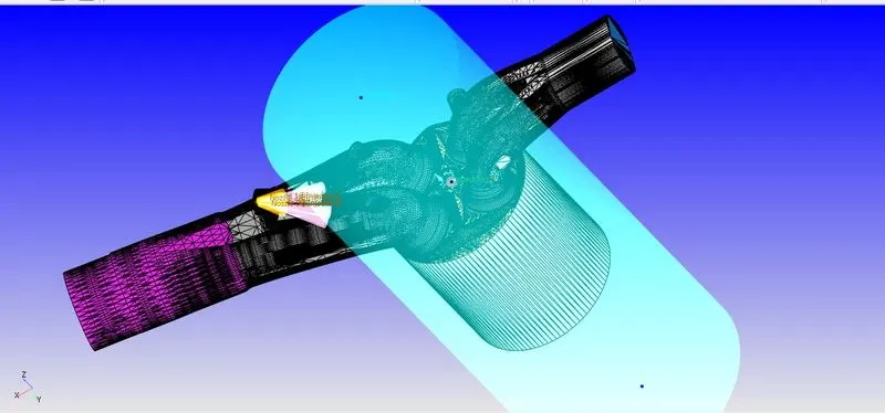
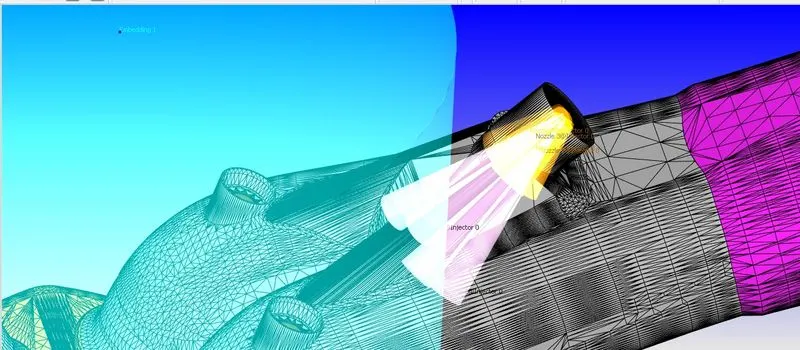
2) Fixed embedding
Adaptive Mesh Refinement :
Fixed Embedding :
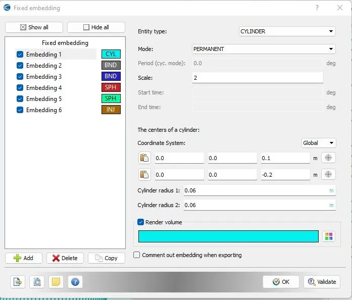
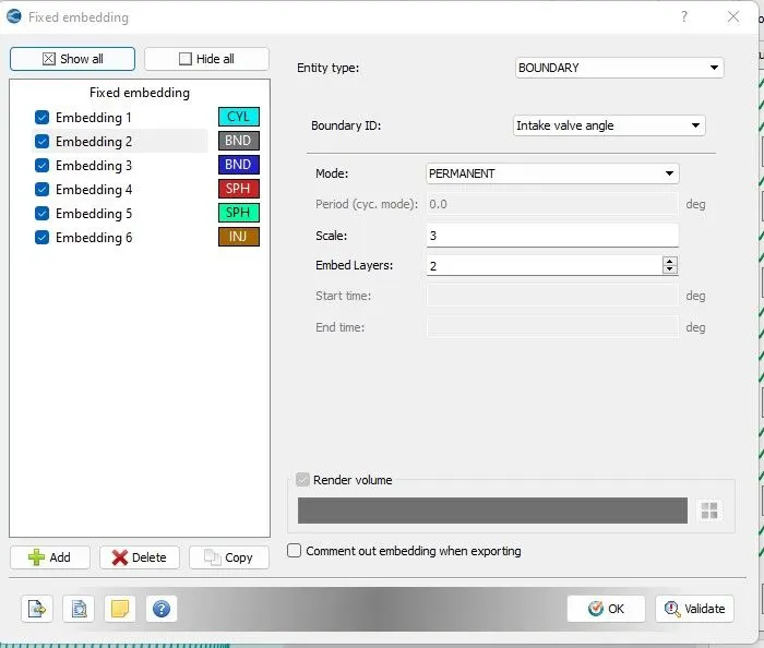
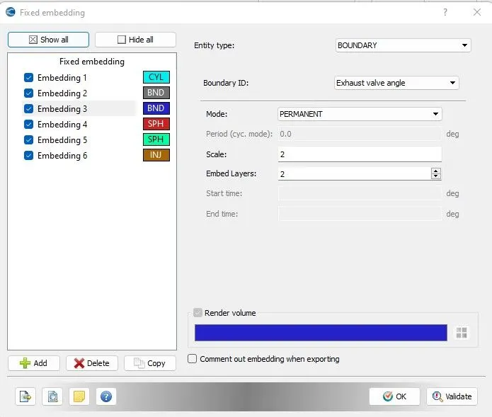
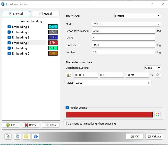
so after this case setup i am going to move in CYGWIN for running the simulation
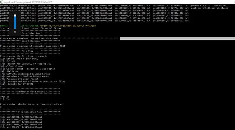
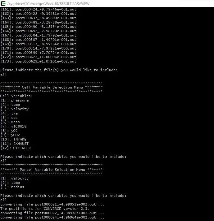
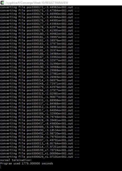
Results:
PLots of Parameters of the Combustion chamber:
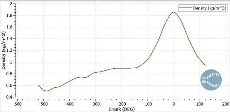
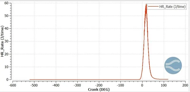
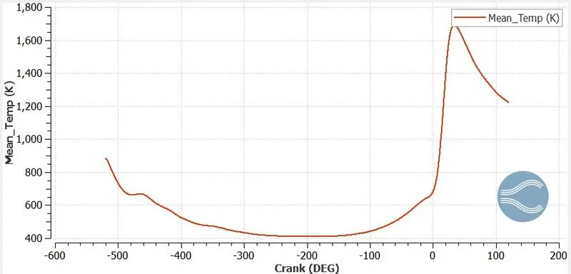
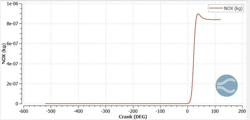
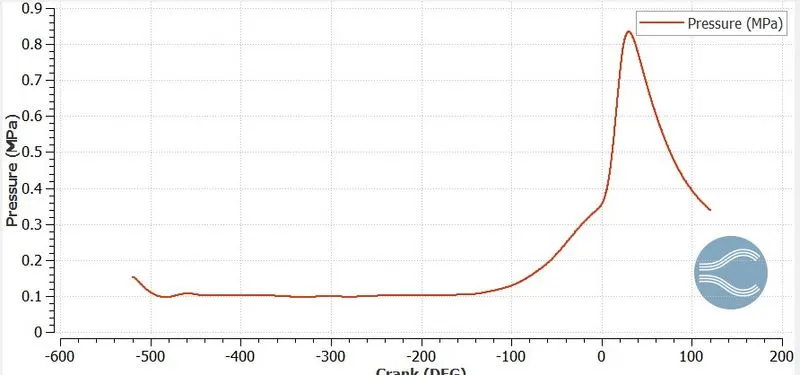
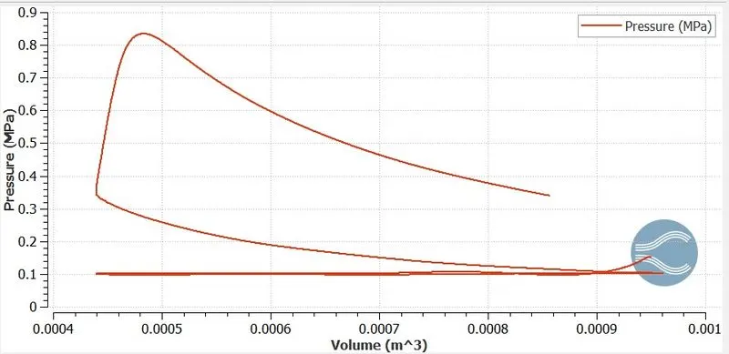
After completion of the simulation i moved to the PARAVIEW for Taking the Animation.
Contours :-
Pressure Contour
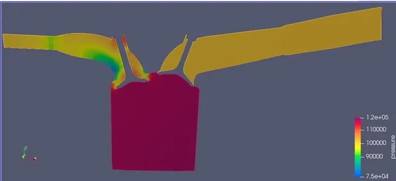
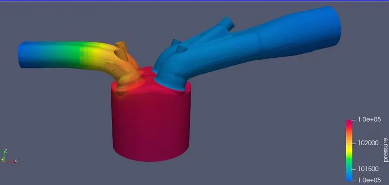
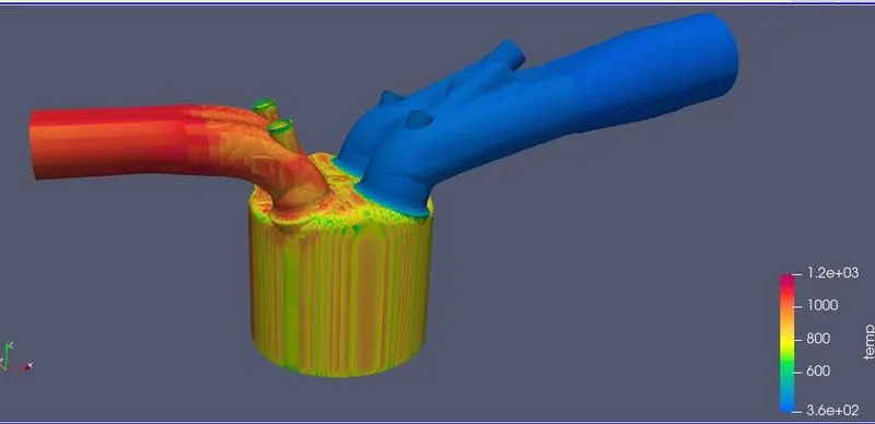
Temperature Contour
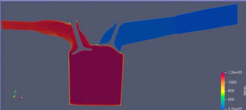
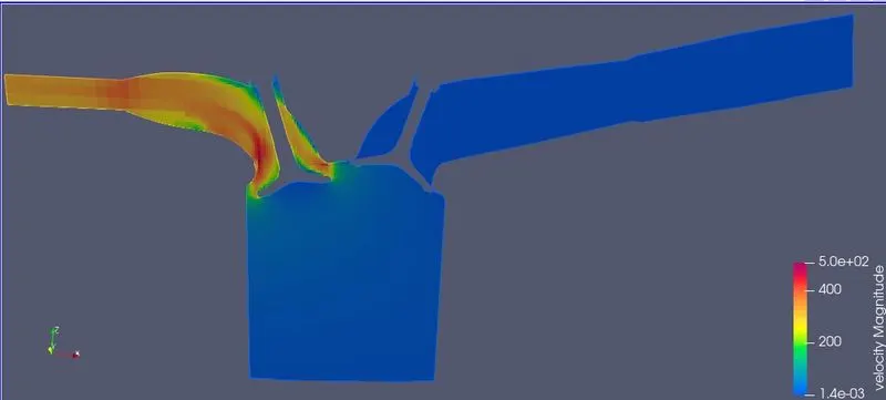
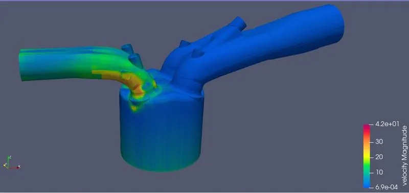
Velocity contour
Velocity Animation youtube link :-