Week 10: Project 1 - FULL HYDRO case set up (PFI)
AIM:
- To run and simulate the Full Hydro simulation in an ICE engine using the supplied inputs We intend to obtain vital engine information by post-processing the results, specifically compression ratio, combustion efficiency, power, and torque.
INTRODUCTION:
- The IC Engine was subjected to a No Hydro simulation in the previous project. Using the same case setup, a full Hydro setup will be performed using Converge tools such as Spray and Combustion modelling. Under relevant headings, the theory relating to the Full Hydro Simulation will be explained in the Case Setup.
THEORY:
- Combustion, also known as burning, is the fundamental chemical process by which energy is released from a fuel and air mixture. The ignition and combustion of the fuel occur within the engine itself in an internal combustion engine (ICE). The energy from the combustion is then partially converted to work by the machine. The engine is made up of a stationary cylinder and a moving piston. The piston is pushed by the expanding combustion gases, which rotates the crankshaft. This motion eventually drives the vehicle's wheels via a system of gears in the powertrain.
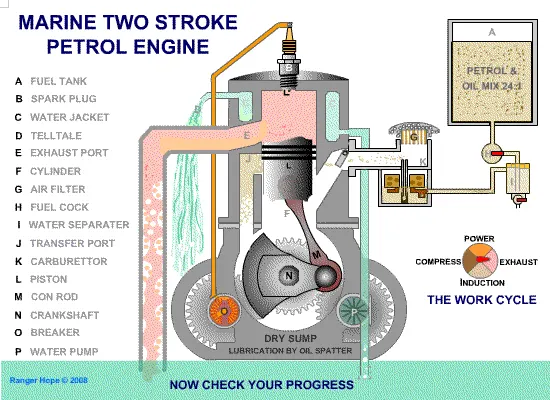
- There are two types of internal combustion engines in use today: spark-ignition gasoline engines and compression-ignition diesel engines. The majority of these are four-stroke cycle engines, which require four piston strokes to complete a cycle. There are four distinct processes in the cycle: intake, compression, combustion and power stroke, and exhaust.
- Spark-ignition gasoline engines and compression-ignition diesel engines operate differently in terms of fuel supply and ignition. During the intake process of a spark ignition engine, fuel is mixed with air and then inducted into the cylinder. The spark ignites the fuel-air mixture after the piston compresses it, resulting in combustion. During the power stroke, the piston is pushed by the expansion of the combustion gases. Only air is introduced into and compressed by a diesel engine. Diesel engines then spray a specific amount of fuel into the hot compressed air, causing it to ignite.
GEOMETRY:
- This simulation made use of the same geometry as the "No Hydro" simulation.
CASE SETUP:
1. APPLICATION TYPE:
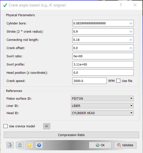
- Crank Angle based IC engine was selected as the application type. The Engine Geometric Parameters provided in the question were used to obtain values for geometry specifications such as bore dia, rpm, and so on.
2. MATERIALS:
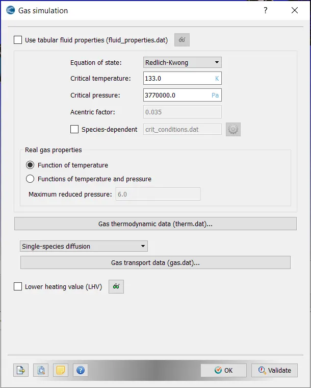
- Gas Simulation:- Default values used,
-PARCEL SIMULATION:
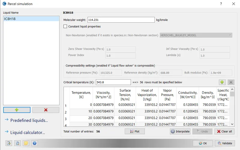
- When we model a simulation that contains fuel spray, the fuel spray is represented as a Lagrangian Parcel. A parcel is a spray model that is based on Langrangian theory. The fuel spray in this case is set up IC8H18.
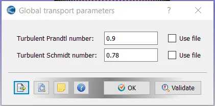
- GLOBAL TRANSPORT PARAMETERS - Default value retained,
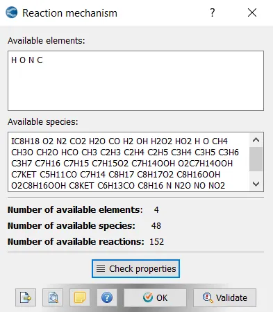
- REACTION MECHANISM:
- therm.dat and mech.dat values loaded into the profile.
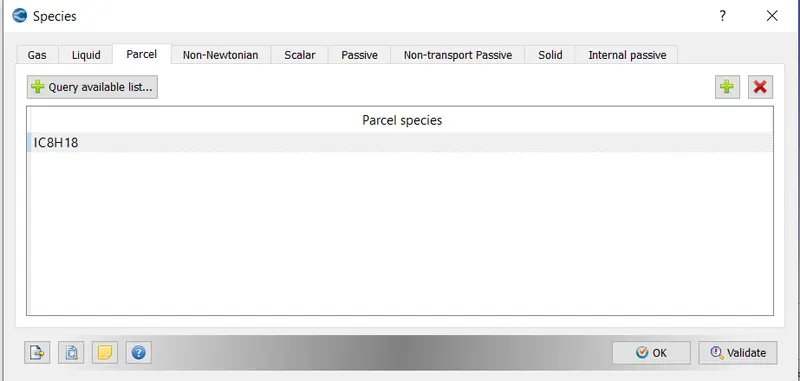
- SPECIES:
- IC8H18 has been added to the 'Parcel',
3. SIMULATION PARAMETERS:
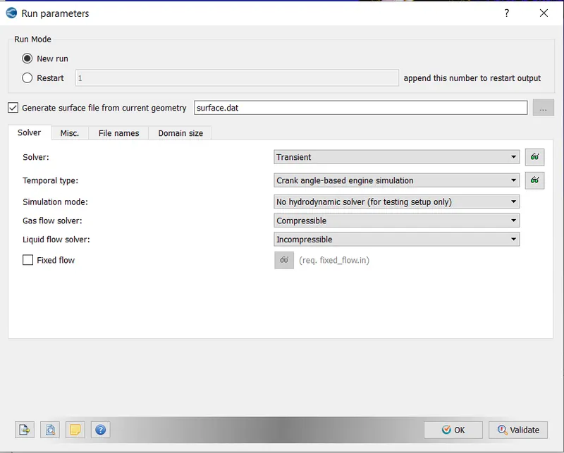
- RUN PARAMETERS:
- Simulation Mode set to Full Hydrodynamic,
-SIMULATION TIME PARAMETERS:
- Values set as shown below,
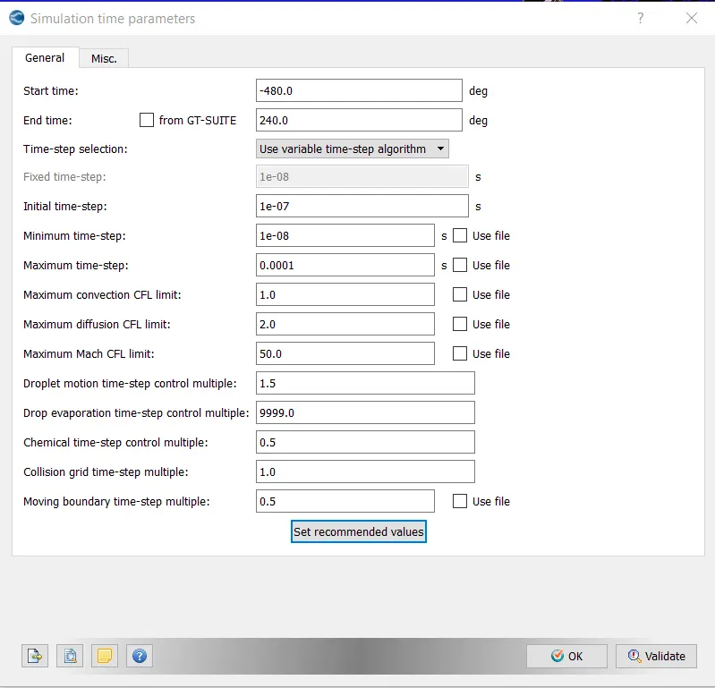
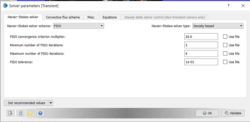
- SOLVER PARAMETERS:
- Default PISO scheme and Density-based solver used.
4. REGIONS AND EVENTS:
A region is a collection of boundaries that are used to distinguish different areas within the boundary. Regions are useful for many reasons.
- Regions are used to specify initial conditions.
- Control Flow Along all Regions (via events)
- Output results are subdivided by region.
- Use grid control techniques based on regions.
- Organize solutions by region
- Regionalize combustion models
- Determine time steps using CFL numbers specific to each region.
Events determine when to flow between regions is permitted.
In this case, four regions have been defined, namely the Cylinder region, Intake 1, Intake 2, and Exhaust regions.
1) CYLINDER REGION:
- Temperature - 1360 K,
- Pressure-185731 Pa ,
-
Species mass concentration computation: It is assumed that stoichiometric combustion of IC8H18 occurs in the combustion chamber.

-
The coefficients of the products in the above-balanced equation are in moles. CONVERGE, on the other hand, only accepts mass fractions. An excel spreadsheet was used to convert moles to mass fractions.
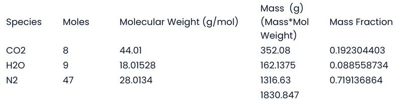
The values are imported into species.
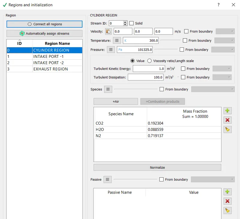
- The ICE engines were classified into four regions, namely Cylinder, intake-1, intake -2 and exhaust region
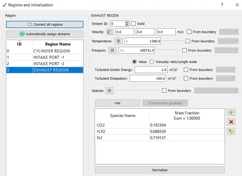
- Cylinder Region:- The species' mass fractions were calculated using the requirement for complete/stoichiometric combustion.
- INTAKE-1: The mass fraction for the fuel-air mixture was entered based on the typical composition of an ICE engine.
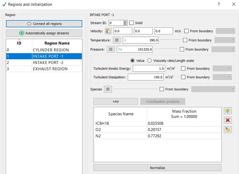
- INTAKE-2: Because air is taken in through intake port 2, the typical air composition has been inserted.
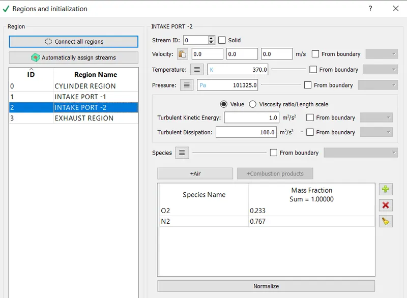
- EXHAUST REGION: Since whatever gas is to be exhausted through the exhaust region comes from the combustion chamber, the exhaust gases have the same composition as the cylinder region.
EVENTS:
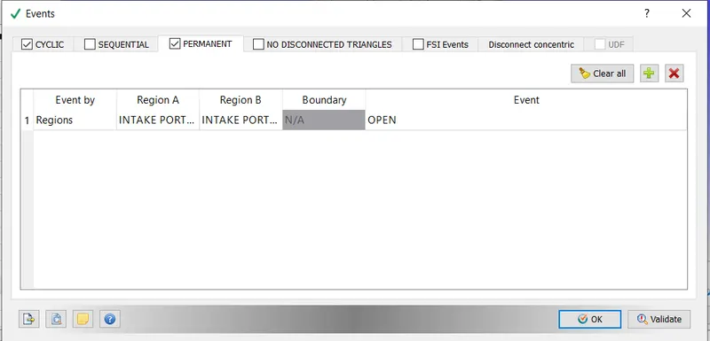
- Events were created to synchronise the cyclic opening of the intake and exhaust ports. The timing of the opening was determined by inspecting the exhaust. in and intake.in files.
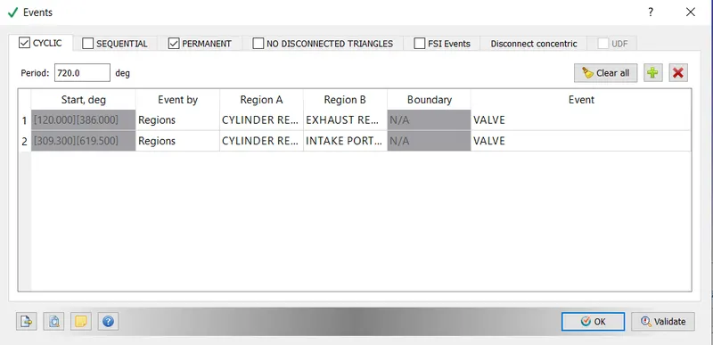
- During the combustion cycle, the intake valves would also be open. As a result, a Permanent event was created.
Boundary condition:
- The ICE engine's components were classified into different regions, as shown below.
-
The boundary condition for each of the components has been set as shown below.
-
Piston:- Boundary Type- Wall,
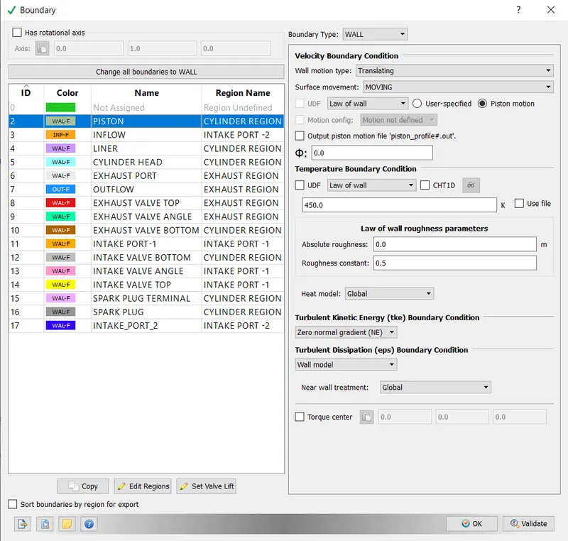
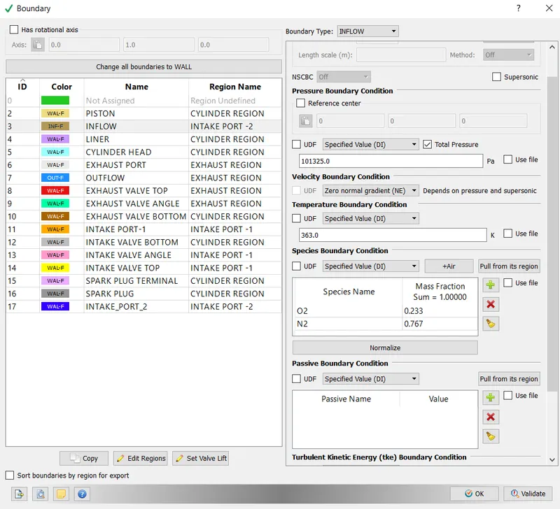
-Inflow:- Boundary Type- Inflow,
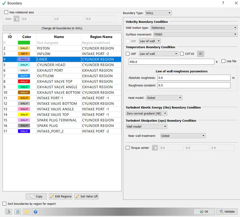
- Liner:- Boundary Type- Wall
- Cylinder Head:- Boundary Type- Wall,
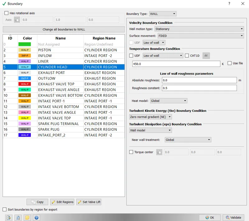
- Exhaust Port:- Boundary Type- Wall,
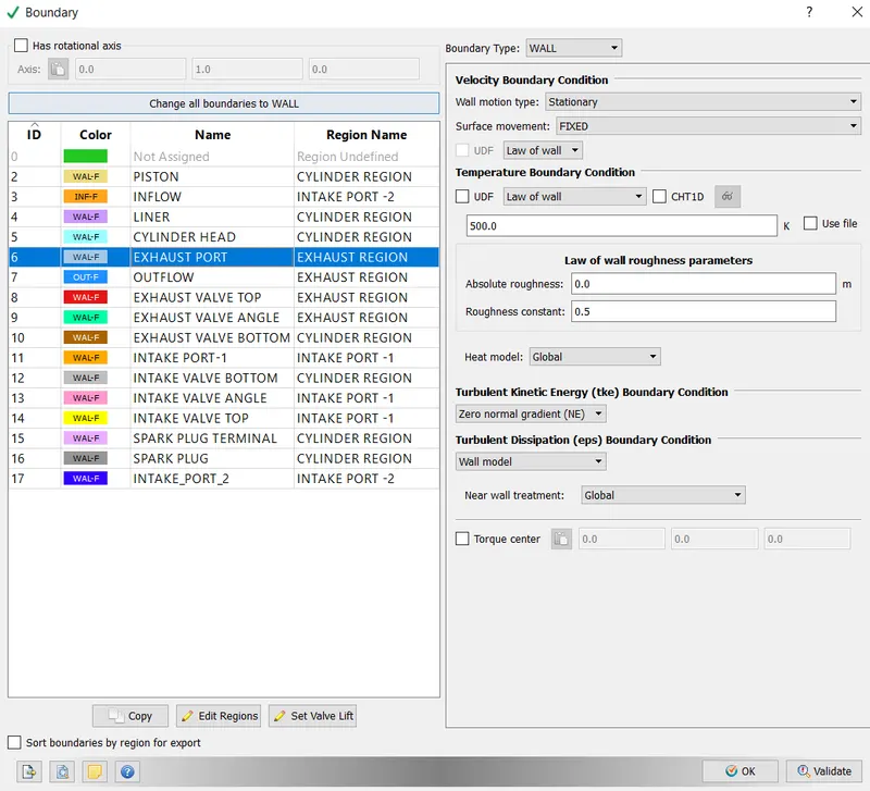
- Outflow:- Boundary Type- Outflow,
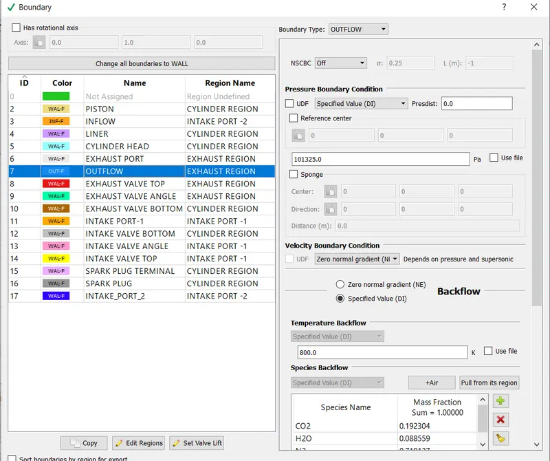
- Exhaust Valve Top - Boundary Type- Wall, Movement as per exhaust_lift.in
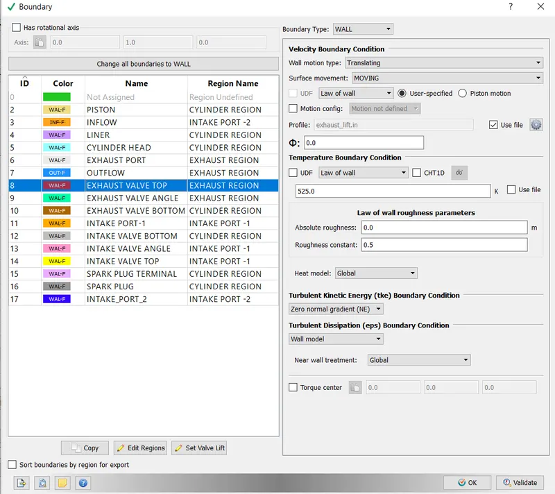
- Exhaust Valve Angle:- Boundary Type- Wall. Movement as per exhaust_lift.in
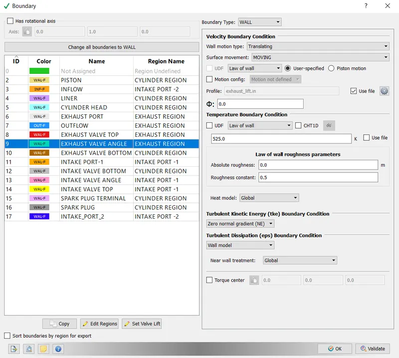
- Exhaust Valve Bottom:- Boundary Type- Wall. Movement as per exhaust_lift.in
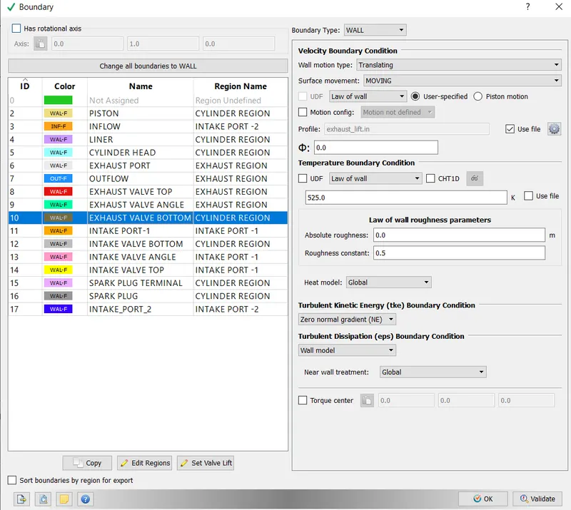
- Intake Port:- Boundary Type- Wall,
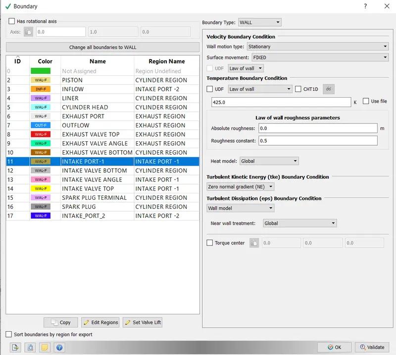
- Intake Bottom:- Boundary Type- Wall. Movement as per intake_lift.in,
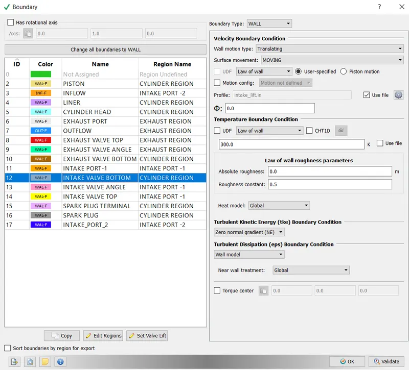
- Intake Valve Top:- Boundary Type- Wall,
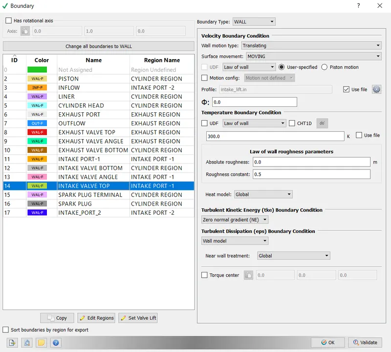
- Spark Plug Terminal:- Boundary Type- Wall,
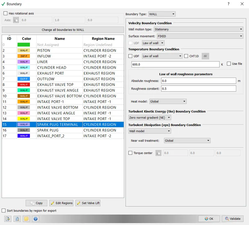
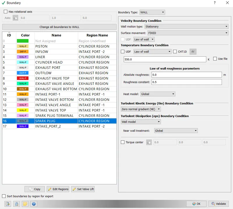
- Spark Plug:- Boundary Type- Wall,
6. PHYSICAL MODELING:
- SPRAY MODELING:
- Spray modelling is necessary because directly solving fluid flow equations describing spray motion is not computationally feasible. As a result, a modelling approach that captures the physics of spray motion is used.
- Converge models liquid sprays with a Langrangian solver for discrete parcels and an Eulerian solver for the continuous fluid domain. Heat, momentum, and mass are transferred between the discrete and continuous phases via the transport equation's source terms.
- At the injector, Converge introduces parcels (collection of drops) into the domain. Each parcel is a collection of identical drops (same, radius, velocity, temperature). CONVERGE solves radius and velocity on a parcel-by-parcel basis.
- The parcel goes through several physical processes.
- Primary Dissection
-Secondary Disintegration
-Drop and Drag
-Collision and cohesion
-Dispersion in turbulence
-Evaporation
- The liquid particles in the fuel interact with the surrounding air when it is injected. This interaction generates drag forces, which result in the propagation of disturbances. If a liquid particle is large enough, it will break up into smaller particles, which will then break down into even smaller particles (Primary and secondary breakup). When smaller secondary particles interact with the surrounding air, they experience one or more of the following physical phenomena: drop drag, collision and coalescence, turbulent dispersion, and evaporation.
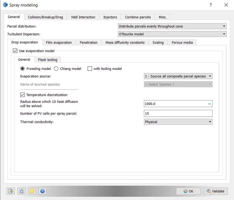
-GENERAL SETUP:
- Parcel Distribution- Distribute Parcels evenly throughout the cone,
- Turbulent Dispersion - O Rourke Model (For gasoline engines, the O Rourke model gives better results),
- Evaporation Model enabled,
- The Frossling model selected,
- Evaporation source:- Source all base parcel species selected (This implies that IC8H18 (liquid) converted to IC8H18 (gas),
- Temperature Discretization enabled,
- Radius above which the 1 D heat equation will be solved = 1000 m,
- No of FV cells per spray parcel =15,
- Thermal conductivity- Physical.
- COLLISION BREAK-UP MODELLING:
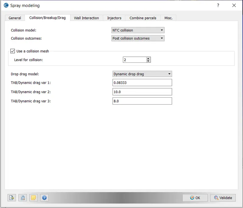
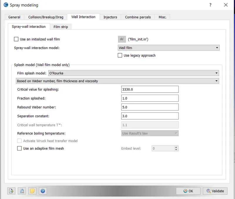
-WALL INTERACTION:
- The default values for Wall Interaction have been retained.
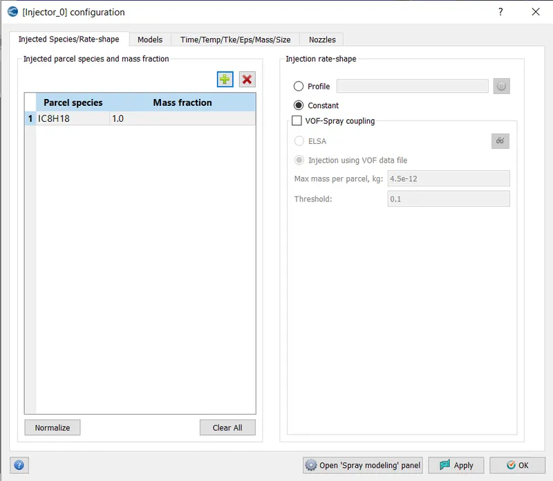
- INJECTOR MODELLING:
- Injected Species: IC8H18 is the parcel species, with a mass fraction of 1.0. Imported injection rate shape profile
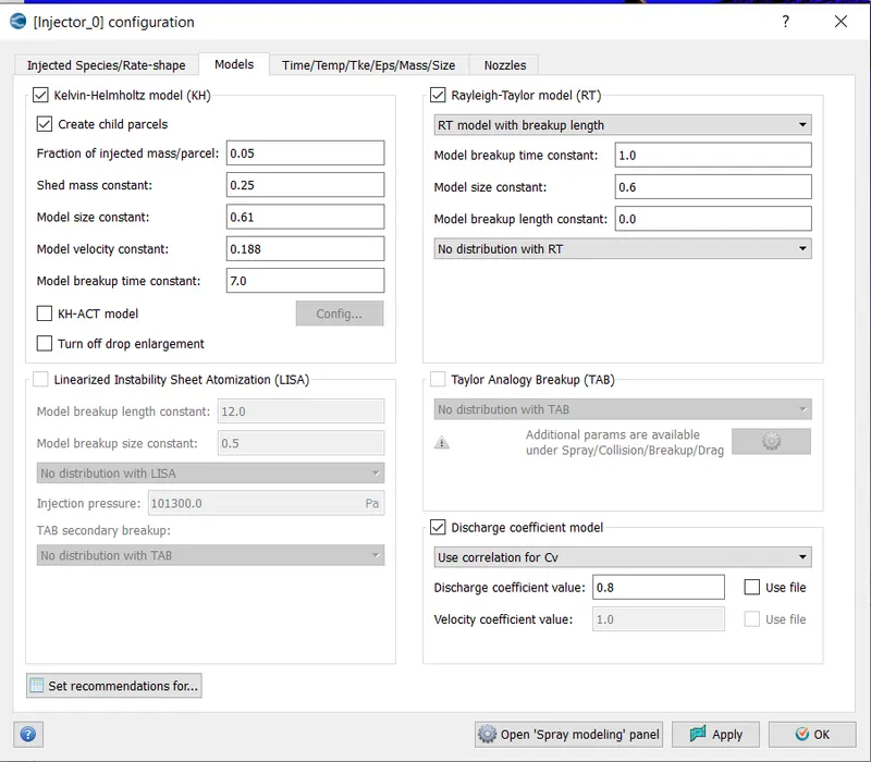
-MODELS:
-
The Kelvin- Helmholtz and Rayleigh- Taylor models were chosen because they are the most commonly used models for solid cone sprays. The default constants have been kept. The discharge coefficient has been set to 0.8.
-
The liquid particle breakup is controlled by the default constants. Although the stability equation governs the process, it does not capture the finer details. The constants control how long it takes for the droplets to break up and the size of the child droplets.
-INJECTOR CONFIGURATION:
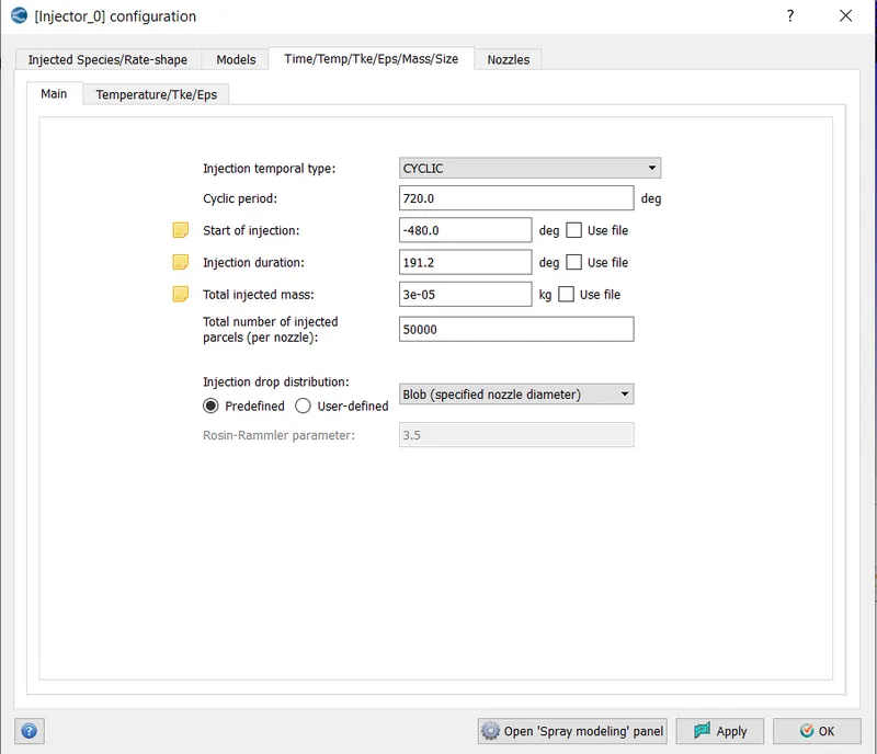
- Injection temporal type - CYCLIC
- Cycle period - 640
- Start of Injection= -480 degrees
- Injection duration = 191.2 degree
-NOZZLE:
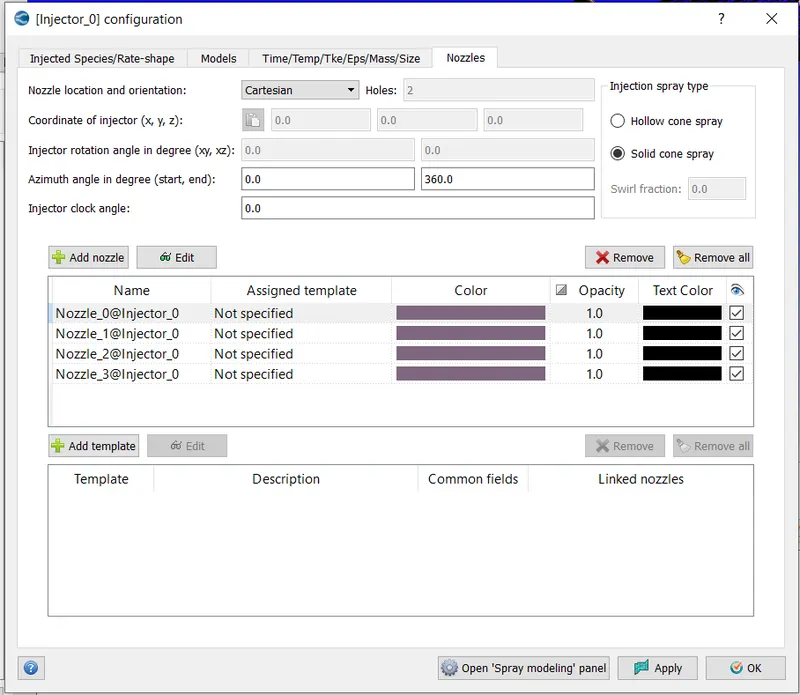
- Nozzle Location and orientation -Cartesian,
- Nozzle diameter=0.00025m,
- Circular Injection -0.000123m,
- Spray Cone Angle -10 degrees,
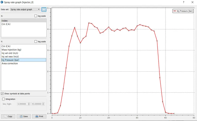
-COMPUTATION OF MAXIMUM INJECTION PRESSURE:
- Peak Injection Pressure = 4.7384 (bar)
- Peak Injection Velocity New = 28.1984 (m/s)
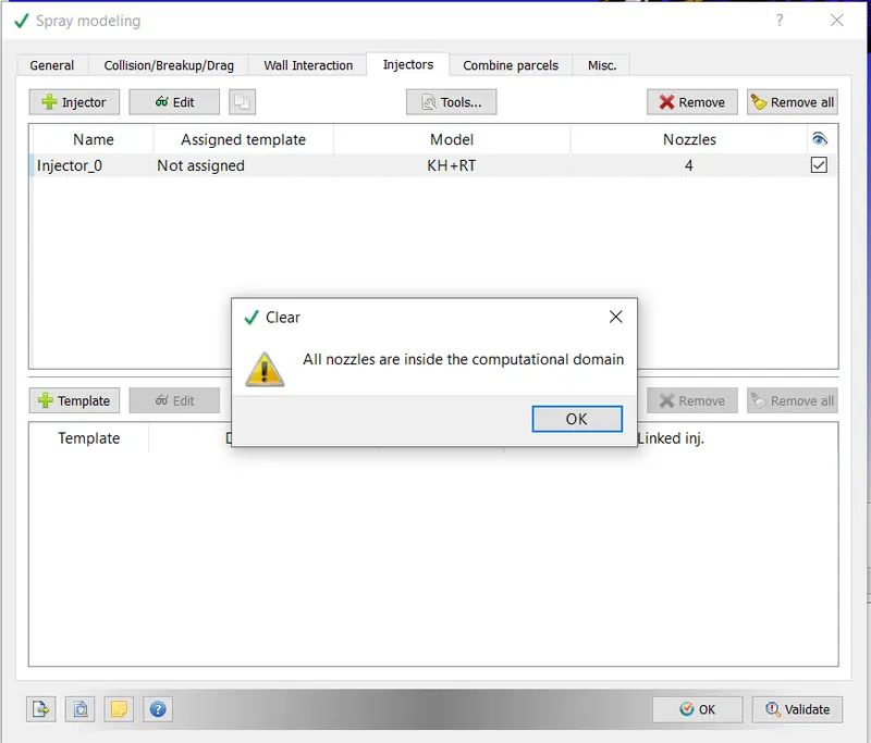
- Nozzle Location Validation To ensure that the newly created nozzles were within the computational domain, the Tools-Validate Nozzle location was chosen, and the following item was displayed.
- COMBUSTION MODELING:
- In an engine, combustion facilitates energy transfer. The SAGE detailed Chemistry Solver is the combustion model used for IC engines. The SAGE solver is the most accurate and predictive way to model combustion. It accurately models ignition and laminar flame propagation.
Based on the principle of chemical kinetics, the SAGE model calculates reaction rates using local conditions. - It determines kinetically limited phenomena such as engine knock and emissions by solving detailed chemical kinetics during combustion. It reads a CHEMKIN-format reaction model and solves ODEs to determine the reaction rate. It also uses the Arrhenius law to calculate the rate of change of species concentration. The Chemistry solver calculates new species mass fractions immediately before solving transport at each time step.

-
Solving SAGE equations is a time-consuming process. CONVERGE includes the following options to reduce computational time.
- Raise the minimum cell temperature and mole fraction of HC species to reduce the number of cells in which combustion calculations are performed.
- Use start and end times to constrain SAGE to specific time intervals.
- Restrict SAGE to specific regions.
- Change the resolve option to Only resolve if the temperature changes by a certain amount.
- Pass analytically calculated Jacobian to the solver using analytical Jacobian.
- Multizone models are used in order to reduce the number of SAGE calculations.
- The case was set up as shown below for simulation purposes.
- The following parameters were entered into the SAGE detailed chemistry solver.
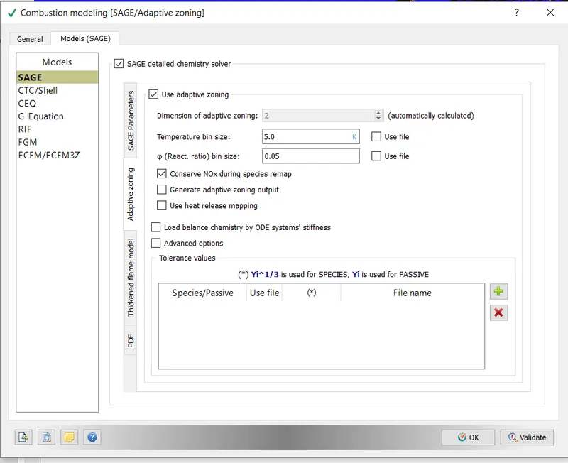
-
The General settings were customised as shown below.
-
The ignition was programmed to start a few crank angles before ignition. The end time for combustion was determined by taking the opening of the exhaust valve into account.
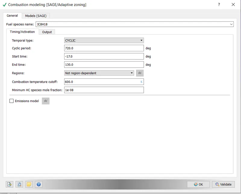
-SPARK-PLUG MODELING:
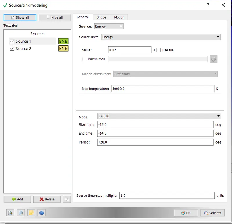
- In a typical spark discharge, the voltage between two electrodes rises until the spark gap fails. The first stage is known as the breakdown phase, and it involves the ionisation of the mixture between the electrodes into plasma. Following the breakdown, phase is the arc phase, in which thin cylindrical plasma expands primarily due to heat conduction and diffusion. The arc phase is followed by the glow discharge phase, during which the energy storage device dumps its energy into discharge circuits. The time scales in the breakdown phase are much lower than those in the arc/glow phase. We specify two phases that briefly overlap in converge simulation.
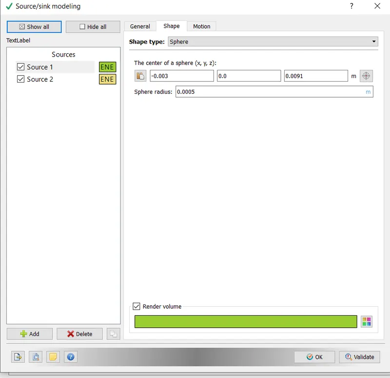
- The source/sink modelling option was enabled in order to model the operation of the Spark Plug. Two 0.5mm radius spherical sources were created. The spark location was used to determine the location of the sphere's centre.
-Shape:
- The following are the general values that were set. The start and end times of the spark were determined using the values provided.
7. GRID CONTROL:
-
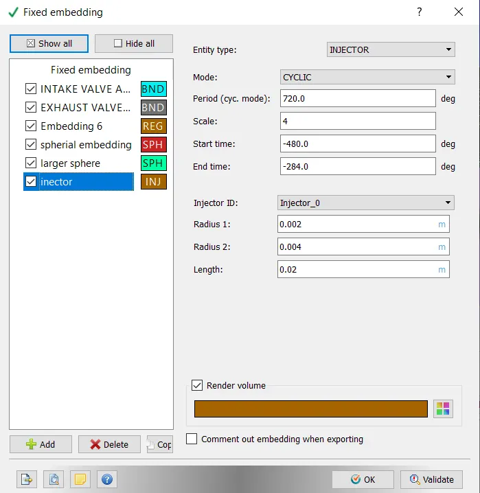
CONVERGE employs a variety of tools to control grid size during a simulation. Fixed embedding refines a grid at specific times and locations. Grid scaling changes the size of the base grid. Adaptive Mesh Refinement changes the grid based on changing and fluctuating conditions.
-
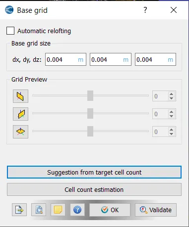
The size of the base grid was set to 0.004.
- ADAPTIVE MESH REFINEMENT:
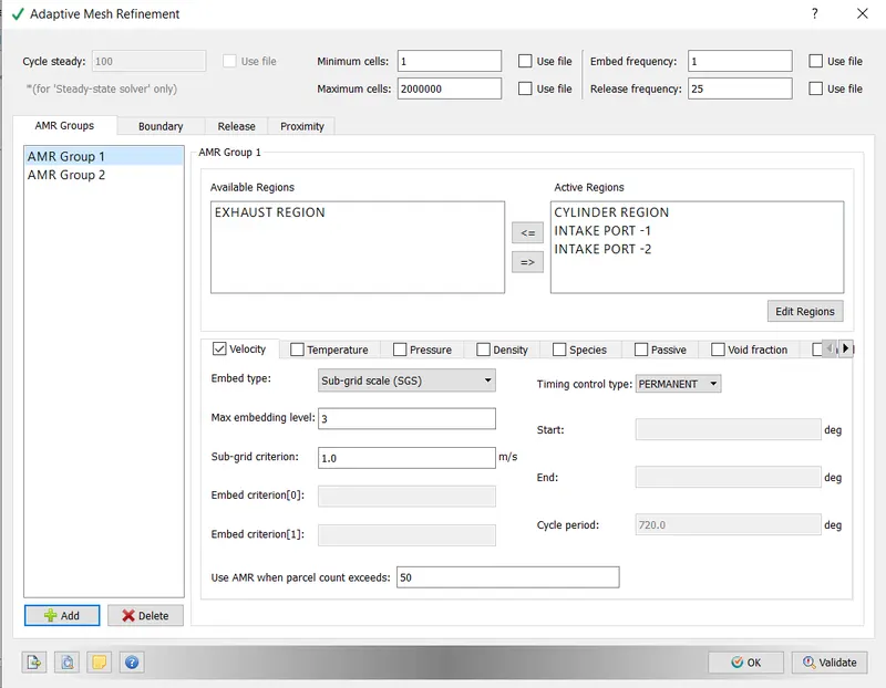
- Two types of AMR are used in the full hydro setup.
- VELOCITY:
- The maximum number of embedding levels is 3.
- 1m/s is the SGS criterion.
- The regions would be automatically refined whenever the curvatures exceeded 1m/s.
- Permanent is the type of timing control.
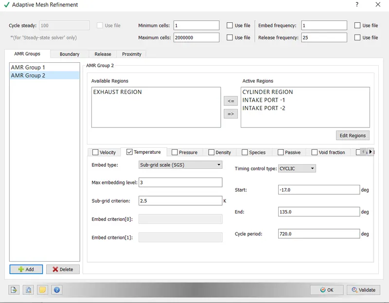
- TEMPERATURE:
- Level 3 maximum embedding
- 2.5 K SGS criterion. When the curvatures exceed 2.5K, the regions are automatically refined.
- Cyclic timing control type,
- FIXED EMBEDDING:
- Fixed embedding allows for local mesh refinement in domains where finer detail is critical to solution accuracy.
- An embedding scale specifies how CONVERGE will refine the grid in that location.
dx embed = dx base/2(embed scale)
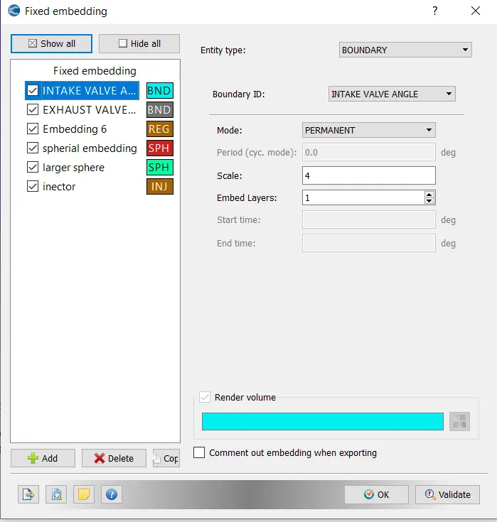
- Fixed embedding was used at the following location for the Full Hydro setup.
- Intake valve angles :
- Boundary type
- Permanent mode
- Scale of Inclusion = 4
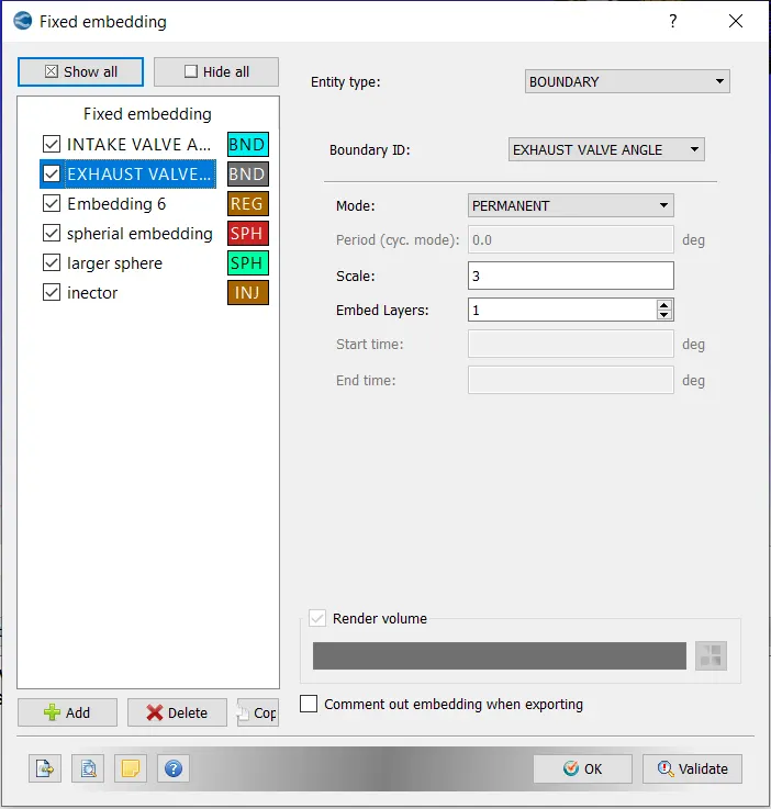
- Exhaust valve angles:
- Boundary type
- Permanent mode
- Scale of Inclusion = 4
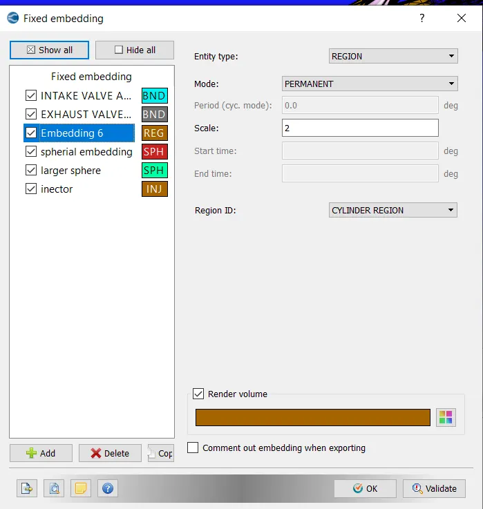
- LINER REGION:
- Entity type- Region
- Mode - Permanent
- Embed Scale = 2
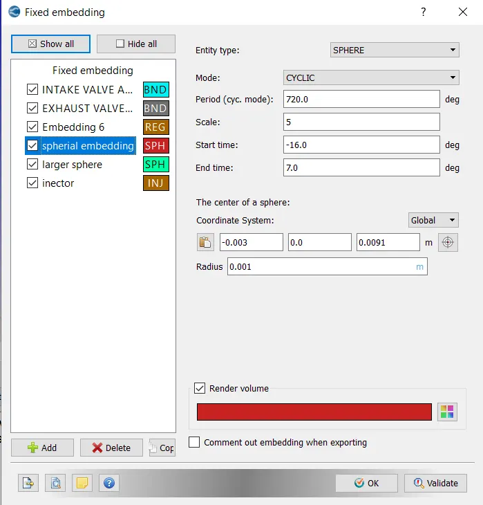
- SPARK PLUG:
- Entity type- Sphere
- Mode - Cyclic
- Embed Scale = 5
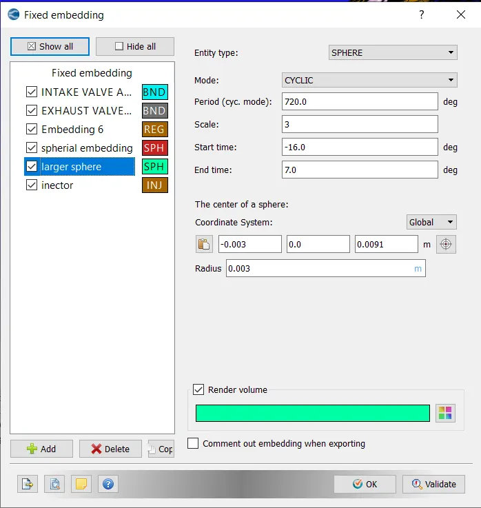
- LARGE SPHERICAL:
- Entity type- Sphere
- Mode - Cyclic
- Embed Scale = 3
- INJECTOR:
8. RESULTS:
a) COMPRESSION RATIO:
- The piston in a reciprocating engine oscillates between the top dead centre and the bottom dead centre. These represent the lowest and highest values, respectively. The compression ratio is the ratio of these two volumes.
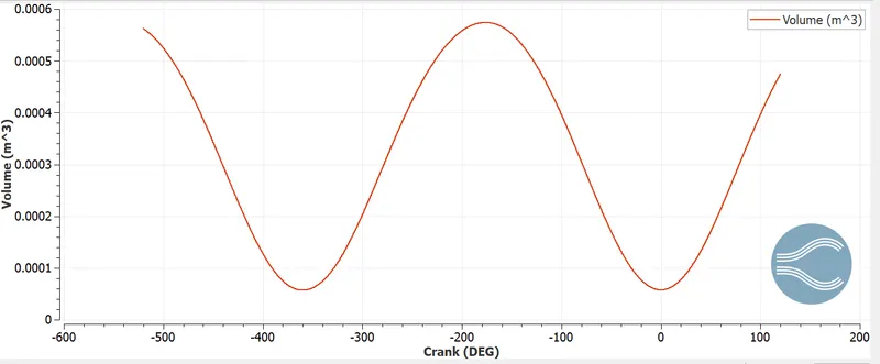
From the above graph,
- Maximum Cylinder Volume = 5.64266 X10^-4 m^3
- Minimum Cylinder Volume =5.63886 X 10^-5 m^3.
- Compression ratio = 9.7.
b) COMBUSTION EFFICIENCY FOR ENGINE:
- The energy released by the burnt fuel to the theoretical energy content of the fuel is defined as combustion efficiency.

- Integrated Heat Release Ratec= 1391.19 J,
- m_f= Mass of Fuel, kg/sec = 3x10^-5 kg,
- LHV= 45.8 MJ/kg,
- η combustion = 97.5 %.
c) POWER & TORQUE CONSUMPTION:
- Power is defined as the rate at which work is done.
- Work = 468.646 Nm,
- Duration= 120.11+120.09= 240.2 degree,
- RPM=3000,
- RPS= 3000/60=50,
- 1 revolution/sec= 360 degrees,
- 50 revolution/sec= 50 *360= 18000 degree,
- Time (sec)= 240.2/18000=0.0133444 sec,
- Power = Work/sec= 468.646/0.0133444 =35119.301 J/sec,
- Power = 35.119 KW,
- Torque:
- The equation for Power is given below
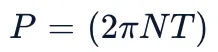
Where,
N= Revolution per sec,
T= Torque,
- Re-arranging for Torque
'T=(P)/(2piN)'
T = 111.878 Nm
- PV DIAGRAM FOR AN IC ENGINE:
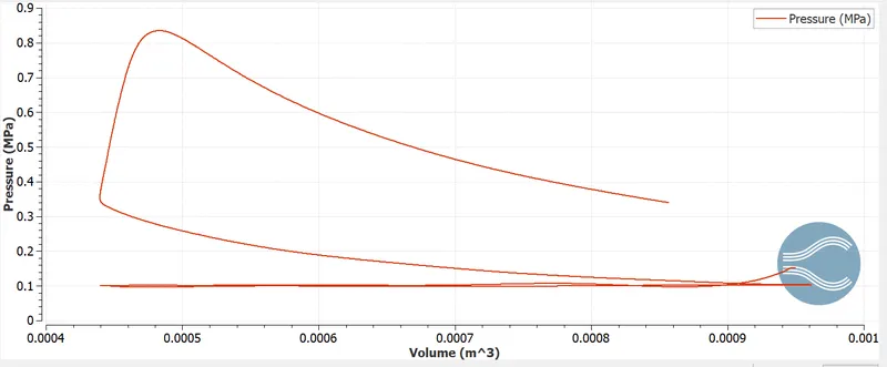
- The area under the PV diagram represents the work completed.
d) NEED FOR WALL HEAT TRANSFER MODEL:
-
Heat loss through the cylinder walls has a negative impact on engine performance. Unwanted consequences include decreased volumetric efficiency, incomplete combustion, and so on. Heat transfer in an ICE is a difficult task to describe because of the various systems (intake and exhaust ports, coolant circuit, lubricant oil subsystem), the various heat transfer mechanisms (convection, conduction, and radiation), and the rapid and unsteady changes that occur inside the cylinder.
-
As a result, accurate modelling of this phenomenon is required. Because of the complexities involved in a mathematical solution, appropriate modelling is required.
e) WHY WE CANNOT USE CFT TO PREDICT WALL TEMPERATURE:
- (CFD) can provide precise and instantaneous information about engine flow (temperature, pressure, and velocity distributions), but it requires temperature boundary conditions for the engine walls, which are typically assumed to be constant throughout the engine cycle. This will disrupt the combustion process, resulting in inaccurate results. Imposing appropriate wall temperature boundary conditions is a difficult task that may necessitate an iterative process. However, when analysing heat transfer within the engine, such calculations with given surface temperatures are insufficient.
- The heat flux and gas properties of the CFD are used as boundary conditions for the solid regions' heat conduction calculation.
f) OTHER PLOTS:
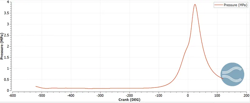
1) Cylinder Pressure:-
- The plot of cylinder pressure versus crank angle is shown below. The cylinder pressure is observed to peak during the compression stroke (compression occurs between -120 degrees to 120 degrees).
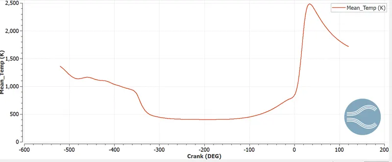
2) Mean Temperature:-
- The graph below shows the peak mean temperature in the cylinder region as a function of the crank angle. Temperature and pressure peaks are observed to coincide and occur during the combustion stroke.
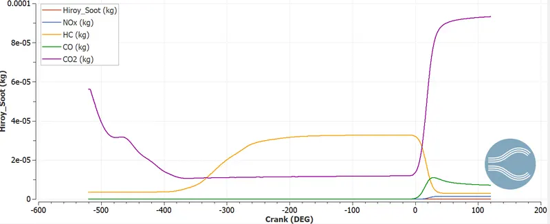
3) Emission:-
- The following graph depicts the emission quantities of various gases as a function of crank angles.
g) ANIMATION:
1) MESH VIEW:
- The plots below show that regions of the mesh are refined in accordance with the Adaptive Mesh refinement and Fixed embedding criteria that were specified during the case setup stage.
2) FUEL PARCEL (SPRAY MODEL):
- The animation below depicts the fuel injection in the engine during the four-stroke combustion process. Spray particles are observed moving through intake ports and through the cylinder.
3) TEMPERATURE CHANGE INSIDE AN IC ENGINE:
- In the above animation, we can see how temperature changes during the four-stroke combustion process in the IC engine. The temperature in the cylinder reaches its maximum during the combustion process, as expected. The temperature in the exhaust port/valves rises during the exhaust stroke.
CONCLUSION:
- A detailed simulation of an IC engine was performed in this project. Spray and combustion modelling was set up in the case setup. Regions and events were used to generate piston, intake, and exhaust valve movement. To obtain finer results, mesh refinement techniques such as AMR and Fixed embedding were used. Aside from that, other aspects such as cylinder mean temperature and pressure, liquid particles and emissions were studied as a function of crank angle. Animations for temperature and spray modelling were also investigated.