Week 10 Challenge
Aim:-
Our Aim is that
1.All checks need to be followed in design of well foundation regarding the stability and the design and also List out all the necessary clauses from IRC codes applicable.
To list out the limits in ULS and SLS for design of a RCC component. Define the limit states and the factors in it as per IRC 112.Also mention shear checks .what is the difference in shear with/without reinforcement?
How to check steining thickness and its steel.What will be the change in PCC and RCC steining.
To discuss in detail the spacing of pile is determined in 6 pile system . describe the bulb theory with neat diagrams showing the stress distributions.
2.To Calculate the reaction exerted on the group of piles from the pier of the bridge.
Load , force And their combination
Horizontal force at bearing level
Base Pressure
Allowable settlement/Differential settlement
Permissible tension at the base of the foundation
The factor of Safety for stability
The limits in ULS for design of a RCC component:-
The ultimate limit state is the design for the safety of a structure and its users by limiting the stress that materials experience. In order to comply with engineering demands for strength and stability under design loads, ULS must be fulfilled as an established condition.
The ULS is a purely elastic condition, usually located at the upper part of its elastic zone (approximately 15% lower than the elastic limit). This is in contrast to the ultimate state (US) which involves excessive deformations approaching structural collapse, and is located deeply within the plastic zone.
If all factored bending, shear and tensile or compressive stresses are below the calculated resistances then a structure will satisfy the ULS criterion. Safety and reliability can be assumed as long as this criterion is fulfilled, since the structure will behave in the same way under repetitive loadings.
Ulimate limit state ULS, the limit state of equilibrium when subjected to various design combinations of ultimate loads the bridge or any its components considered as a rigid body shall not became unstable, So this is the one equilibrium as awhole it should be equilibrium position .And limit state of strength the bridge or any of its components shall not lose its capacity to sustain the various ultimate load combinations by excessive deformation , transformation into the mechanism, rupture , curshing or buckling.So that is the one we can consider that as a part of the limit state of strength .The next one is called under ulimate limit states , so the limit state of equlibrium that is we are not going to internal stresses that from externally whether it is in stable condition or not equilibrium condition then limits state of strength we are considering that one the stresses.
According to IRC-112, their are variour ULS limits that are
Ultimate limit state of linear elements for bending and axial forces section-8, IRC-112-2011.
Ultimate limit state of 2&3-dimensionl elements for out of the plan and in planned loading effect, section-9, IRC-112-2011.
Ultimate limit state of shear, punching shear & torsion, section-10 , IRC-112-2011
Ulimate limit state of induced deformation,section11,IRC-112-2011.
The limits in SLS for design of a RCC component:-
Serviceability limit states SLS, limit state of internal stress ;the internal stresses developed in the materials of structural elements shall not exceed the specified magnitudes when subjected to the combinnation of serviceability designations. The streeses are to be estimated using resistance models to represent the behavior of structure as stipulated in the code , so this is the one we shall consider for internal stress.
The Serviceability Limit State (SLS) is defined as the state of design beyond which a structural system loses operationally its serviceability for the actual service load that the structure is subjected to.
Shear Check :-
A shear test is designed to apply stress to a test sample so that it experiences a sliding failure along a plane that is parallel to the forces applied.
Current practice in the world for shear design many various practices is going on ,As shearis more critical force than other actions on bridge's
Difference in Shear with/Without reinforcement:-
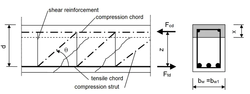
Shear reinforcement is required to prevent propagation of diagonal cracks. The diagonal tension cracks develop in the beam, when the strength of the beam in diagonal tension is less than the strength in flexural tension. On this type of failure, the cracks start to develop due to the flexure at mid-span.
The design of concrete members for shear without stirrups has became a major issue worldwide especially for bridge decks as the shear capacity according to the new regulations often given sinificant smaller values than the one predicated by former codes. Therefore nowadays stirrups are required in bridge decks. In addition the safety of existing structure mainly build without shear reinforcement has been brought into focus.
Steining:-
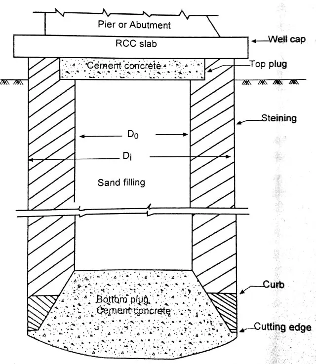
Steining is a wall or shall type of structure made up of RCC, and which helps to transfer the load to the curb. It serves as an enclosure for excavating the soil for the penetration of the foundation well.
Thickness of steining & Reinforcement
Spacing and Tolerances for Pile as per IS2911:-
The pile shall not vary from the planned location by more than 100 mm (4 inches). For abutments, this tolerance is 25 mm (1 inch). Also, piles may not have more than a 20 mm per meter (1/4 inch per foot) variation at their tip from the vertical or batter.
- For vertical driven or bored cast-in-situ piles an angular deviation of 1.5 percent and for raker piles an angular deviation of 4.0 percent should not usually be exceeded except exceptional cases.
- Foundation piles should not deviate more than 75.00 mm or 1/6 times of its diameter whichever is less and for piles having more than 600mm diameter deviation should be 75.00mm or 1/10 times of its diameter whichever is higher from their designed coordinates at the operational level of the piling rig/platform.
- In case of a single pile in a column, positional tolerance should not be more than 50 mm or 1/6 times of its diameter whichever is less and for piles having more than 600mm diameter deviation should be maximum of 100mm.
- In some exceptional cases, greater tolerance may be prescribed for marine piles/driven over water and for raking piles.
Beyond the above tolerances for pile and to such an extent that the resultant eccentricity of applied load cannot be taken care of by the redesign of pile cap or pile ties, the Foundation piles must be replaced or extended by one or more additional piles.
Permissible Tolerances for Piles :-
Precast Concrete Pile:-
| Sl No | Description | Tolerance (millimetre) |
| i. | Cross-sectional dimensions | ± 5.00 |
| ii. | Length | ± 25 |
| iii. | Surface irregularities | 5 mm with 3 m straight edge |
| iv. | Bow for total length | 1mm/m length (max. 20mm) |
Driven Piles:-
| Sl No | Description | Tolerance (millimetre) |
| i. | Cross-sectional dimensions | +50 mm, -10 mm |
| ii. | Deviation | 75 mm |
| iii. | Tilt | 1 in 150 |
| iv. | Pile top level | ± 25 mm |
Bored Piles:-
| Sl No | Description | Tolerance (millimetre) |
| i. | cross-sectional dimensions | +50 mm, -10 mm |
| ii. | Deviation | 50.00 mm |
| Iii. | Tilt | 1 in 150 |
| iv. | Pile top level | ± 25 mm |
Raker (inclined) piles:-
| Sl No | Description | Tolerance (millimetre) |
| i. | Maximum rake for bored piles | 1/6 |
| ii. | Maximum rake for cast-in-situ piles | 1/6 |
| iii. | Maximum rake for precast driven piles | 1/4 |
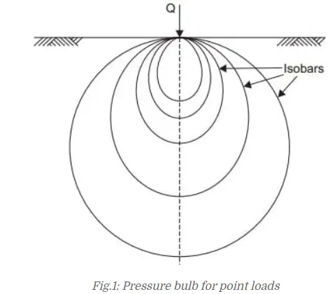
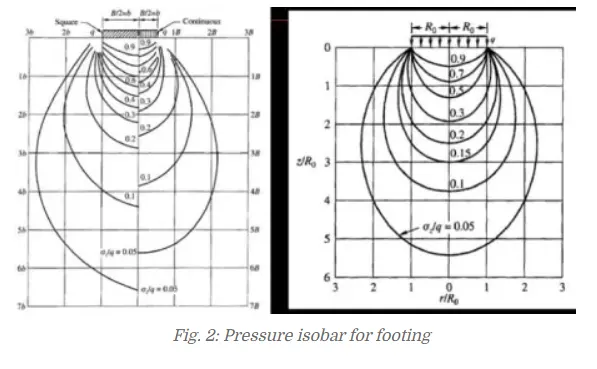
Pressure Bulb Theory:-The vertical pressure at each point on the pressure bulb is the same. Pressure at points inside the bulb are greater than that at a point on the surface of the bulb; and pressures at points outside the bulb are smaller than that value.
An isobar or pressure bulb is a stress contour or a line which connects all points below the ground surface at which the vertical pressure is the same. In fact, an isobar is a spatial curved surface and resembles a bulb in shape; this is because the vertical pressure at all points in a horizontal plane at equal radial distances from the load is the same. Thus, the stress isobar is also called the ‘bulb of pressure’ or simply the ‘pressure bulb’. The vertical pressure at each point on the pressure bulb is the same. Pressure at points inside the bulb are greater than that at a point on the surface of the bulb; and pressures at points outside the bulb are smaller than that value. Any number of pressure bulbs may be drawn for any applied load, since each one corresponds to an arbitrarily chosen value of stress. A system of isobars indicates the decrease in stress intensity from the inner to the outer ones and reminds one of an ‘Onion bulb’. Hence the term ‘pressure bulb’. An isobar diagram, consisting of a system of isobars appears somewhat as shown in Fig
2.To Calculate the reaction exerted on the group of piles from the pier of the bridge:-
Given Data:-
Total Vertical reaction is 5929 kN
Total moment about L-L axis is 1092 kN.m
A total moment about the T-T axis is 530 kN
Total horizontal force along L-L axis is 83 kN
Total horizontal force along T-T axis 172 kN
Load on each pile= [P/N]±[Mx*x/Σx2]±[My*y/Σy2]
P is vertical load on the pile cap
N is number of the pile in a group
Mx is total moment due to force in X-axis
My is total moment due to force in Y-axis
Σx2 is sum of the square of the distance of pile in X-direction
Σy2 is sum of the square of the distance of pile in Y-direction
X is Distance of pile from the X-axis
Y is Distance of pile from the Y-axis
Solution:-
Σx2 =3*1.8^2+3*(-1.8^2)
=19.44 m^2
Σy2 =2*3.2^2+2*(-3.2^2)
=40.96 m^2
Load on P1
=5929/6+[530*(-1.8)/19.44]+[1092*(3.2)/40.96]
=1024.676 kN
Load on P2
=5929/6+[530*1.8/19.44]+[1092*(3.2)/40.96
=1122.384 kN
Load on P3
=5929/6+[530*(-1.8)/19.44]
=939.086 kN
Load on P4
=5929/6+[530*1.8/19.44]
=1037.234 kN
Load on P5
=5929/6+[530*(-1.8)/19.44]+[1092*(-3.2)/40.96
=853.936 kN
Load on P6
=5929/6+[530*1.8/19.44]+[1092*(-3.2)/40.96
=952.150 kN
Result:-
Load acting on Pile 1 is 1024.676 kN
Load acting on Pile 2 is 1122.384 kN
Load acting on Pile 3 is 939.086 kN
Load acting on Pile 4 is 1037.234 kN
Load acting on Pile 5 is 853.936 kN
Load acting on Pile 6 is 952.150 kN